
Preparation of Sn nano-film by direct current magnetron sputtering and its performance as anode of lithium ion battery
ZHAO Ling-zhi(赵灵智)1, 2, HU She-jun(胡社军)2, 3, LI Wei-shan(李伟善)2,
HOU Xian-hua(侯贤华)2, LI Chang-ming(李昌明)1, 2, ZENG Rong-hua(曾荣华)2, RU Qiang(汝 强)2
1. Faculty of Material and Energy, Guangdong University of Technology, Guangzhou 510006, China;
2. Department of Chemistry, South China Normal University, Guangzhou 510006, China;
3. Department of Mathematics and Physics, Wuyi University, Jiangmen 529020, China
Received 15 July 2007; accepted 10 September 2007
Abstract: Sn thin film on Cu foil substrate as the anode of lithium ion battery was prepared by direct current magnetron sputtering(DCMS). The surface morphology, composition and thickness and the electrochemical behaviors of the prepared Sn thin film were characterized by scanning electron microscopy(SEM), X-ray diffraction(XRD), inductively coupled plasma atomic emission spectrometry(ICP), cyclic voltammetry(CV) and galvanostatic charge/ discharge(GC) measurements. It is found that the Sn film is consists of pure Sn with an average particle diameter of 100 nm. The thickness of the film is about 320 nm. The initial lithium insertion capacity of the Sn film is 771 mA?h/g. The reversible capacity of the film is 570 mA?h/g and kept at 270 mA?h/g after 20 cycles.
Key words: lithium-ion battery; anode; Sn; nano-thin film; direct current magnetron sputtering
1 Introduction
Since Sony realized the commercial applications of lithium ion battery in 1990, many materials for lithium ion battery have been developed[1-4]. In the early lithium ion battery, graphite was used as anode owing to its good cycling performances, but the theoretical specific capacity of graphite is only 372 mA?h/g. Therefore much works have been done to find a substitute for graphite[5-6]. Sn was found to have a high theoretical specific capacity of 990 mA?h/g. However Sn suffers severe volume variations during electrochemical reactions with lithium ions, which results in heavy body stress of anode materials during charging/discharging and finally capacity fades. The volume fraction of Sn could increase by 676% after Li ions were inserted into it[7]. This drawback limits the practical application of Sn as the anode of lithium ion battery. Many efforts were made to overcome this drawback, most of which are focused on the use of Sn alloys instead of pure Sn[8-10]. The cyclic stability of Sn can be improved to a great extent but its capacity is reduced significantly by the alloying. Recently, it was found in our lab that the Sn film electrode consisted of fine and compact Sn particles (less than 0.5 ?m) electrodepositing onto Cu foil collector has a better cyclic stability than the electrode consisted of large and separated Sn particles (about 3 ?m)[11].
It is well known that physical vapor deposition (PVD) has proved to be a simple, manageable and efficient method to fabricate smooth and dense thin film over a large area. In the present work, direct current magnetron sputtering(DCMS) is used to fabricate the Sn thin film on Cu foil substrate, and the surface morphology, the composition and the electrochemical behaviors of the prepared Sn thin film are characterized by using scanning electron microscopy(SEM), X-ray diffraction(XRD), inductive coupled and plasma atomic emission spectrometry(ICP), cyclic voltammetry(CV) as well as galvanostatic charge/discharge(GC) measure- ments.
2 Experimental
Sn thin film was deposited onto Cu-foil substrate in a deposition chamber evacuated to 5×10⁻³ Pa by using multi-target radio frequency magnetic sputtering-4 (RFMS-4) apparatus. Among other things, the pure Sn target (99.9%, d59 mm×4 mm) was used as starting material, the substrates were cleaned by a conventional procedure with alcohol and acetone ultrasonic cleaner which was fixed onto a rotatable holder at a distance of 59 mm above the target, pure argon (99.999%) with airflow 60 mL/min was input into the chamber after vacuum reached the demand degree, direct current(DC) power of 100 W was turned on to bombard the substrate for 5 min so as to not only clean the substrate again but also improve the adhesive force between the film and substrate because the surface of the substrate became rougher after high-energy ion beam bombardment. Subsequently, radio frequency(RF) power with 100 W was turned on to melt the Sn target to eliminate the impurity of the surface. Then the Sn thin film was obtained after sputtering Sn target for 20 min with a D.C. power of 250 W.
The composition and structure of the fabricated thin film was identified by an X-ray diffractometer(Y-2000 XRD systems, Dandong, China) with Cu Kα radiation. The morphology of the sample was observed with SEM (JSM-6380-LA, JEOL). The content of the Sn deposited onto the Cu-foil was determined by ICP.
CV and GC measurements were carried out by 8-channel testing system (Solartron1480, England) at room temperature with CR2016 button cells, in which metallic lithium foils were used as both counter and reference electrodes, and the Sn film deposited was used as a working electrode. The electrolyte was 1 mol/L LiPF6 dissolved in a 1?1?1 (volume ratio) mixture of ethylene carbonate(EC), diethyl carbonate(DEC) and ethyl methyl carbonate(EMC). The septum was a tiny eyelet polypropylene membrane (Celgard2400). The button cells were charged/discharged at 0.1 mA/cm2 and cycled between 0-1.5 V versus Li/Li+ for the working electrode, and cyclic voltammograms were performed between 0-2.0 V versus Li/Li+ with scanning speed 1 mV/s. The button cells were assembled in an argon-filled glove box (Mikrouna, sukei1220/750). In this paper, the discharge process responds to lithium intercalation and the charge process to lithium deintercalation.
3 Results and discussion
Fig.1 presents the surface morphology of the prepared film observed by SEM. It can be seen that the material is composed of compact base film covered with
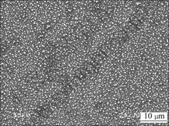
Fig.1 Surface morphology of Sn film observed by SEM
uniform spherical particles. This suggests that the Sn is deposited on the Cu-foil substrate in the form of particles first and then they form into film. The particle size on the Sn film is about 100 nm. The Sn mass of the film was obtained by ICP. The estimated thickness of the Sn film is 320 nm.
Fig.2 shows the XRD pattern of the Sn film on Cu foil substrate. For comparison, the XRD pattern of a pure Sn and the Cu foil for the preparation of Sn film are also shown in Fig.2. The diffraction peaks of Sn are similar to the Sn target. The diffraction peaks of Cu also appear in the XRD pattern of the Sn film. This should be ascribed to diffraction of the Cu foil substrate. No other diffraction peaks can be observed for the Sn film and thus it is a pure Sn. It should be noticed that there is no any diffraction for Cu-Sn alloys. This suggests that during the film fabrication either Cu-Sn alloy cannot form or it may form but its content can be neglected.
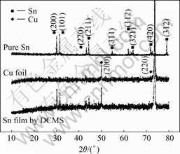
Fig.2 XRD patterns of pure Sn, Cu foil and Sn film prepared by DCMS
The cyclic voltammograms of the Sn film for the first several cycles at 0.1 mV/s are shown in Fig.3. It can be seen from the negative sweep of the first cycle that the current is small when the potential is higher than 0.5 V. This small current is ascribed to the reduction of surface

Fig.3 Cyclic voltammograms of Sn film electrode
Sn oxide formed in air. The solid electrolyte interface (SEI) layer cannot be formed on the oxide. The insertion of lithium ions takes place quickly after the reduction of Sn oxide and large current appears at the potential lower than 0.5 V. In the second cycle, the current for the SEI formation can be observed from 1.7 V to 1.1 V in negative sweep. Several current peaks for the insertion of lithium ions into Sn appears from 0.7 V and the corresponding current peaks of the extraction of lithium ions from Sn can be observed when the potential is reversed.
In the following forward cycles, the significant current for the SEI formation can be observed, indicating that the fresh Sn surface is always available during cycling. This can be ascribed to the crack of bulk Sn due to volume change during the intercalation and de-intercalation. In the sixth cycle, the current for the SEI formation is hardly observed, suggesting that less of fresh Sn surface is available after the Sn is cycled further[12].
The shape and the position of the current peaks for the insertion and extraction of lithium ions is similar between the second and the sixth cycles, except the larger insertion current appears at the potential lower than 0.25 V. This larger current can be ascribed to the insertion of lithium ions in the deeper Sn. The current for the reduction of surface Sn oxide in the first cycle and the SEI formation in the initial several cycles accounts for the loss of lithium insertion capacity of Sn.
There are three current peaks in the range of potentials 0.68-0.53 V, 0.53-0.38 V and 0.38-0.10 V which are correspondent to the formation of Sn alloys with different content of lithium[13]:
xLi+Sn→LixSn (x=0-4.4)
They are LixSn (x<0.7), LiySn (0.7<y<3.5) and LizSn (3.5<z<4.4)[14].
The charge-discharge curves of the Sn film electrode at a current 0.1 mA/cm2 are shown in Fig.4. In the first discharge curve, higher potential can be observed when the capacity is lower than 200 mA?h/g, as shown in Fig.4. This can be ascribed to the reduction reaction of the surface Sn oxide and the formation of SEI. In subsequent discharge curves, there are three plateaus at about 0.63, 0.47 and 0.37 V, corresponding to the CVs insertion in the range 0.68-0.53 V, 0.53-0.38 V and 0.38-0.10 V, respectively.
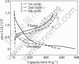
Fig.4 Charge-discharge curves of Sn film electrode at current 0.1 mA/cm2
Fig.5 shows the variation of lithium insertion capacity of the Sn film with cycle numbers. The first discharge capacity of the Sn film electrode is 771 mA?h/g. The Sn film electrode has a reversible capacity of 570 mA?h/g, which is far higher than the theoretical capacity of graphite. There is 26% of capacity loss from 1st cycle to 2nd cycle. After 20 cycles, the discharge capacity of Sn film becomes 270 mA?h/g, and there is 53% of capacity loss from 2nd cycle to 20th cycle. It is believed that optimization of conditions for Sn film preparation can improve its electrochemical properties further.
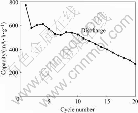
Fig.5 Variation of lithium insertion capacity of Sn film electrode with cycle numbers
4 Conclusions
A Sn nanometer film can be prepared directly on Cu foil substrate by direct current magnetron sputtering (DCMS). The film is pure Sn and consists of particles with an average diameter of 100 nm. The thickness of the film estimated by ICP is about 320 nm. It has a high lithium insertion capacity and a good cyclic stability. The initial lithium insertion capacity of the film is 771 mA?h/g. The reversible capacity of the film is 570 mA?h/g and hold on 270 mA?h/g after 20 cycles. Apparently, the performances of the film need to be improved further for its practical application in lithium ion batteries.
References
[1] ANG K, MENG Y S, BR?GER J, CLARE P G, GERBRAND C. Electrodes with high power and high capacity for rechargeable lithium batteries [J]. Science, 2006, 311(2): 977-980.
[2] L? Dong-sheng, LI Wei-shan. Study on electrochemical impedance spectroscopies of insertion and deinsertion of lithium ion in spinel lithium manganese oxide [J]. Acta Chimica Sin, 2003, 61(2): 225-229. (in Chinese)
[3] ZUO X X, XU M Q, LI W S, SU D G, LIU J S. Electrochemical reduction of 1,3-propane sultone on graphite electrode and its application in Li-ion battery [J]. Electrochem Solid-State Lett, 2006, 9: A196-A199.
[4] LU Lei, ZUO Xiao-xi, LI Wei-shan, LIU Jian-sheng, XU Meng-qing. Study on the preparation and performances of PMMA-Vac polymer electrolyte for lithium ion battery use [J]. Acta Chimica Sin, 2007, 65(6): 475-480. (in Chinese)
[5] YUAN L, KONSTANTINOV K, WANG G X, LIU H K, DOU S X. Nano-structured SnO2-carbon composites obtained by in situ spray pyrolysis method as anodes in lithium batteries [J]. J Power Sources, 2005, 146: 180-184.
[6] L? Chun-ping, ZHAO Xin-bing, CAO Gao-shao, ZHU Tie-jun. Effects of graphite on Zn-Sb alloys as anode materials for lithium-ion batteries [J]. Trans Nonferrous Met Soc China, 2000, 10(2): 204-208.
[7] WANG G X, AHN J H, LINDSAY M J, SUN L, BRADHURST D H, DOU S X, LIU H K. Graphite-tin composites as anode materials for lithium-ion batteries [J]. J Power Sources, 2001, 97/98: 211-215.
[8] KIM Y U, LEE S, LEE C K, SOHN H J. Enhancement of capacity and cycle-life of Sn4+δP3(0≤δ≤1) anode for lithium secondary batteries [J]. J Power Sources, 2005, 141: 163-166.
[9] NULI Y N, ZHAO S L, QIN Q Z. Nanocrystalline tin oxides and nickel oxide film anodes for Li-ion batteries [J]. J Power Sources, 2003, 114: 113-120.
[10] TAN Chun-lin, LU Dong-sheng, LI Wei-shan, XU Meng-qing, ZHOU Dai-ying, HU She-jun. Study of Sn/Ni alloy films electrodeposited as anode materials for Li-ion batteries [J]. Rare Met Mater Eng, 2007 (In press). (in Chinese)
[11] LI Chang-ming, HUANG Qi-ming, ZHANG Ren-yuan, LI Wei-shan, ZHAO Ling-zhi, HU She-jun. A comparison of the performances of two kinds of Sn films as lithium-ion insertion electrodes prepared by electrodepositon [J]. Acta Metall Sin, 2007, 43(5): 515-520. (in Chinese)
[12] TRIFONOVA A, WACHTLER M, WAGNER M R, SCHROETTNER H, MITTERBAUER C, HOFER F, MOLLE K C, WINTER M, BESENHARD J O. Influence of the reductive preparation conditions on the morphology and on the electrochemical performance of Sn/SnSb [J]. Solid State Ionics, 2004, 168: 51-59.
[13] COURTNEY I A, DAHN J R. Electrochemical and in-situ X-ray diffraction studies of the reaction of lithium with tin oxide composite [J]. J Electrochem Soc, 1997, 144: 2045-2052.
[14] HUGGINS R A. Lithium alloy negative electrodes formed from convertible oxides [J]. Solid State Ionics, 1998, 113/115: 57-67.
(Edited by LAI Hai-hui)
Foundation item: Projects(50771046; 20373016) supported by the National Natural Science Foundation of China; Project(05200534) supported by the Natural Science Foundation of Guangdong Province, China; Project(2006A10704003) supported by the Key Project of Guangdong Province, China; Project(2006Z3-D2031) supported by the Key Project of Guangzhou City, China
Corresponding author: HU She-jun; Tel/Fax: +86-20-39310256; E-mail: husj@scnu.edu.cn

