J. Cent. South Univ. Technol. (2009) 16: 0131-0135
DOI: 10.1007/s11771-009-0022-6
Directly searching method for slip plane and its influential factors based on critical state of slope
Lin Hang(�� ��), CAO Ping(�� ƽ), GONG Feng-qiang(����ǿ), LI Jiang-teng(���), GUI Yi-lin(������)
(School of Resources and Safety Engineering, Central South University, Changsha 410083, China)
Abstract: In order to determine the slip plane of slope directly by the calculation results of strength reduction method, and analyze the influential factors of slope stability, a numerical model was established in plane strain mode by FLAC3D for homogeneous soil slope, whose parameters were reduced until the slope reached the critical state. Then FISH program was used to get the location data of slip plane from displacement contour lines. Furthermore, the method to determine multiple slip planes was also proposed by setting different heights of elastic areas. The influential factors for the stability were analyzed, including cohesion, internal friction angle, and tensile strength. The calculation results show that with the increase of cohesion, failure mode of slope changes from shallow slipping to the deep slipping, while inclination of slip plane becomes slower and slipping volume becomes larger; with the increase of friction angle, failure mode of slope changes from deep slipping to shallow slipping, while slip plane becomes steeper and upper border of slip plane comes closer to the vertex of slope; the safety factor increases little and slip plane goes far away from vertex of slope with the increase of tensile strength.
Key words: slope; strength reduction; slip plane; stability; influential factors
1 Introduction
In recent years, with the rapid development of computational technique, the numerical calculation methods are widely adopted in the stability analysis for slope. The numerical calculation methods can be divided into two groups[1-3]: the first is the strength reduction method; and the second is the numerical calculation combined with the optimum searching method. The second numerical method combines the numerical results with the critical slip plane searching theory; it supposes some slip planes first, then tries to find out the plane with the smallest safety factor by the stress calculation results. For example, KIM and LEE[3] found the slip plane by the revised strategy of searching method according to the stress field calculated by finite element method. It is obvious that, this method needs the optimum theory to find out the slip plane after numerical calculation, and only uses the result of numerical calculation indirectly. So scholars have done much work to find that strength reduction method (SRM) can do this work directly, for there are many indexes to define the critical slip plane in the SRM, such as plastic zone contour[4], shear strain increment contour[5-6], grid aberration zones[7], and so
on. These indexes can search the slip plane well in certain situations, but the elements in most numerical methods are the ones with constant parameters, so the index of plastic zone contour will cause some errors. The elements on the slip plane suffer from both shear failure and tensile failure, and the elements with small shear strain will also be on the slip plane with some degree of tensile failure, but the index of shear strain increment cannot reflect this. In addition, shear strain and plastic zones are not easy to measure in the real situation, so we have to find another index to describe the slip plane. As it is known, the displacement and deformation of slope can be easily measured. They are often chosen as the ideal indexes to describe the state of slope in the real situation.
In view of the above stated issues, a new direct slip plane searching method was proposed in this paper, which mainly focused on the mechanism of slope deformation failure. The details of the numerical model, the parameters of cohesion, friction angle and tensile strength were discussed by finding out the relationship among these parameters, safety factor and slip plane. During the discussion, one parameter is changed while the other parameters are fixed to a constant value.
2 Slip plane searching method
2.1 Numerical model
A numerical model is founded in plane strain mode by FLAC3D for a homogeneous soil slope, with 20 m of slope height, 45? of slope angle, and 1 m of model thickness, as shown in Fig.1. Model element will affect the calculation result. After comparing time consumed and calculation precision, the whole model is divided into three parts, which consists of 816 elements and 1 176 grids, part I with 12��8 elements, part II with 40��8 elements, and part III with 40��10 elements. The size of model also affects the result, so the model is built large enough to reduce the size effect, with the length from slope toe to the left boundary of 30 m, length from slope vertex to the right boundary of 55 m, and length from slope toe to the bottom boundary of 20 m that is equal to the slope height. The soil parameters are as follows: unit weight 25 kN/m3, elastic modulus 10 MPa, poisson ratio 0.3, cohesion 42 kPa, internal friction angle 17?, and tensile strength 10 kPa. The numerical model is fixed in both horizontal and vertical directions on bottom boundary, in horizontal direction on both sides, and the upper boundary is free. The tolerance for calculation is 10-5, and 30 000 steps for the up limit calculation steps, which are sufficiently accurate[8].
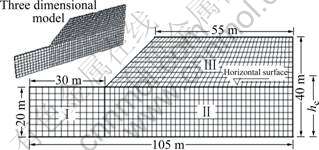
Fig.1 Numerical calculation model of slope
The strength reduction method[4-7, 9-13] are adopted to calculate the safety factor of slope, and the calculation convergence criterion is chosen to describe the state of slope in this paper.
2.2 Searching method for single slip plane
For the fixed slip plane, there are many calculation methods for safety factor[14-17], such as the limit equilibrium method and the finite element method. But in the real situation, the location of slip plane is often unknown. If the shape of slip plane is supposed to be circular, we can get the satisfying result without the complicated optimum technique of searching plane. But if the shape of slip plane is complicated, the work will be very difficult even with the optimum technique. And there has not been any satisfying method to locate the complicated slip plane until recently. But during slope stability analysis by applying SRM, when the slope comes to the verge of failure, displacement of slip block will mutate to cause large and unlimited plastic flow, the program cannot find a solution that can meet both the static equilibrium equation and the stress��strain relationship[12]. So based on the mechanism of deformation, the displacement characteristic of slope can be adopted to search the critical slip plane by directly using the results of SRM, without any other optimum method.
Some tests and practice show that[18], when the slope comes to the failure state, the obvious local shear deformation can be observed in a narrow area, as shown in Fig.2. Once the strain localization occurs, deformation of soil will be concentrated in one small area, the deformation outside this area consists mainly of rigid movement after unloading, and slope will slip along the localization area. The particle displacements of both sides along localization area are very different, the deformation grad is large, and the failure and slip plane of slope are obvious, as shown in Fig.3. In other words, when slope comes to the failure state, the unlimited slipping occurs in one part while compared to another part of slope[13]. We can also get this conclusion from the calculation result by SRM, as shown in Fig.4. So it is convinced to choose the displacement contour line to describe the critical slip plane of slope.
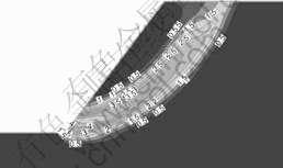
Fig.2 Shear strain increment contour of slope
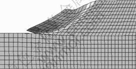
Fig.3 Failure deformation of slope
Fig.4 shows two parts of slope, slipping part and stable part, divided by the displacement contour line with the value of 0.5. Contour lines are densely near the slip plane, and the value of contour line becomes larger and larger when it comes near the slope surface, which indicates slipping in these fields. The values of contour lines outside the unstable parts are the same and very small, which indicates the stable state of these areas. So the boundary of these two parts can be defined as the slip plane, and the data of the boundary are obtained by FISH program, as shown in Fig.5.
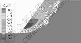
Fig.4 Displacement contour for slope that goes to verge of failure
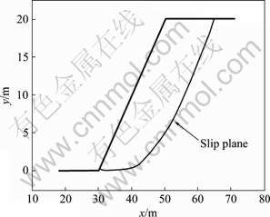
Fig.5 Quantization for location of single slip plane
2.3 Multiple slip plane searching method
In order to place the reinforced structure precisely, it is necessary to determine the number of the secondary slip planes in the slope, the location of potential shear opening, and the slipping sequence of each slip plane. So not only the first slipping plane but also all the slip plane with the safety factor lower than the preset value are needed. LIU and ZHENG[19] solved this problem by confining the displacement of slope surface sequentially. But for some slopes with complicated geometry, it will be boring to confine each grid on the slope surface without the convenient computational work. So we try to find out another method to do this work. Firstly, we suppose that soil under slip plane will not collapse; then we set the soil under the slip plane as the elastic material. So if the height of elastic soil changes (shown in Fig.1), different slip planes with different safety factors can be obtained, which is the proposed multiple slip planes searching method.
The detail process of the proposed method is as follows. The area within an height of he is set to be elastic, and he varies to get different slip planes with different safety factors. The results are shown in Table 1 and Fig.6. Table 1 shows that cases 1 and 2 reflect the similar safety factor, for the reason that the slip plane is above the horizontal surface, which can also support our hypothesis that soil under the slip plane does not affect the safety factor. For cases 3-6, the safety factors of the slope increase with the increase of he. The safely factor differences from cases 2-5 to case 1 are 0.000 4, 0.174 4, 0.474 7, 1.143 0, 4.688 5, respectively, which shows that, increment of safety factor becomes larger and larger with the increase of he at the same increment. In addition, Fig.6 shows that with the increase of he, location of potential shear opening goes higher and higher, the upper border of slip plane comes closer to the vertex of slope, and slip plane becomes steeper.
Table 1 Relationship between elastic area height and safety factors
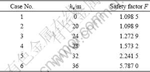
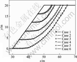
Fig.6 Locations of multiple slip plane of slope for different cases
3 Parameters analysis
3.1 Effect of cohesion
Cohesion (c) varies from 4.2 to 268.8 kPa. Let the gradient be Kc, so the cohesion of each variety step can be obtained from the following equation:
ci=Kcci-1 (1)
where ci and ci-1 are the cohesions of ith and (i-1)th step of variety.
The relationship between safety factor and cohesion is listed in Table 2, and the relationship between slip plane and cohesion is shown in Fig.7. From Table 2, it can be seen that, when c varies in the studied range, safety factor varies in the range of 6.232��100%. From Fig.7, it can be seen that, with the increase of cohesion, the failure mode of slope changes from shallow slip to deep slip, the inclination of slip plane becomes slower, the upper border comes closer to the vertex of slope, and the volume of slip block becomes larger. When the cohesion varies from 4.2 to 67.2 kPa, potential shear opening locates higher the slope toe; while the cohesion varies from 133.4 to 268.8 kPa, the slip plane runs through the left horizontal surface.
Table 2 Relationship between cohesion and safety factor
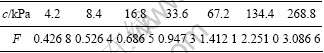
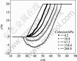
Fig.7 Relationship between cohesion and slope slip plane
3.2 Effect of friction angle
Friction angle (��) varies from 1.75? to 44.37?, and the gradient is K��, so the friction angle of each variety step can be obtained from the following equation:
 (2)
(2)
where ��i and��i-1 are the friction angles of ith and (i-1)th step of variety.
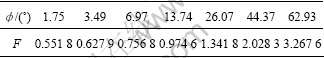
The relationship between safety factor and�� is listed in Table 3, which shows that, with the increase of �� the safety factor increases at the same time. The safety factor differs in the range of 4.922��100% with different friction angles of ��.
Table 3 Relationship between friction angle and safety factor
The relationship between slip plane and friction angle is shown in Fig.8, which shows that, with the increase of ��, the failure mode of slope changes from deep slip to shallow slip, the slip plane becomes steeper and steeper, and the volume of slip block become smaller, which is the right opposite to the relationship between friction angle and cohesion. In addition, when �� varies from 1.75? to 3.49?, the slip plane runs through the left horizontal surface; when �� varies from 6.97? to 44.37?, potential shear opening locates at the slope surface.
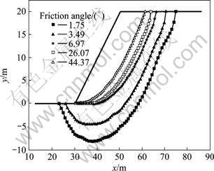
Fig.8 Relationship between friction angle and slope slip plane
3.3 Effect of tensile strength
In many situations, soil mass underground is compressively loaded, so the failure mode of soil is often regarded as the shear failure only. But there are many cases showing that the tensile strength can also affect the stability of slope significantly[20]. So when the numerical calculations are done, the tensile strength as well as the shear strength should be considered.
In this study, the tensile strength (��t) of soil varies from 0.1 to 10 MPa, and the gradient is Kt, so ��t of each variety step can be obtained from the following equation:
 (3)
(3)
where  and
and  are the tensile strength of ith and (i-1)th step of variety.
The relationship between safety factor and ��t is listed in Table 4, which shows that the safety factor varies from 1.084 0 to 1.115 2, and increases with the increase of ��t. The difference between maximum and minimum of safety factor is 2.878%, which is much smaller than that of cohesion and friction angle. In addition, the relationship between slip plane and ��t is shown in Fig.9. It can be seen from Fig.9 that, location of slip plane changes little in the large range of ��t, which moves far away from the slope surface.
Table 4 Relationship between tensile strength and safety factor
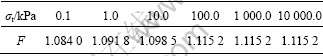
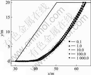
Fig.9 Relationship between tensile strength and slope slip plane
4 Conclusions
(1) A new slip plane searching method is proposed based on the slope deformation mechanism. The boundary between the stable block and unstable block is defined as the slip plane. The displacement contour is used to find out the boundary, while the data of the slip plane are obtained for the single slip plane by the FISH program. For the multiple slip plane, the elastic heights are set differently to find different slip planes.
(2) The effect of parameters such as cohesion, friction angle, and tensile strength on the safety factor and slip plane of slope is discussed. The results show that, with the increase of cohesion, the failure mode of slope changes from shallow slip to the deep slip, and the inclination of slip plane becomes more and more slower; with the increase of friction angle, the failure mode of slope changes from deep slip to the shallow slip, inclination of slip plane becomes steeper, while the upper boundary of slip plane comes closer to the slope vertex, and the volume of slip block becomes smaller; and with the increase of tensile strength, the safety increases at the same time, and the location of slip plane goes far away from the slope surface.
References
[1] SU Yong-hua, ZHAO Ming-hua, ZHANG Yue-ying. Numerical method of slope failure probability based on Bishop model [J]. Journal of Central South University of Technology, 2008, 15(1): 100-105.
[2] WAN Wen, CAO Ping, FENG Tao. Improved genetic algorithm freely searching for dangerous slip surface of slope [J]. Journal of Central South University of Technology, 2005, 12(6): 749-752.
[3] KIM J Y, LEE S R. An improved search strategy for the critical slip surface using finite element stress fields [J]. Computers and Geotechnics, 1997, 21(4): 295-313.
[4] MATSUI T, SAN K C. Finite element slope stability analysis by shear strength reduction technique [J]. Soils and Foundations, 1992, 32 (1): 59-70.
[5] UGAI K, LESHCHINSKY D. Three-dimensional limit equilibrium and finite element analysis: A comparison of results [J]. Soils and Foundations, 1995, 35(4): 1-7.
[6] CHENG Y M, LANSIVAARA T, WEI W B. Two-dimensional slope stability analysis by limit equilibrium and strength reduction methods [J]. Computers and Geotechnics, 2007, 34(3): 137-150.
[7] GRIFFITHS D V, LANE P A. Slope stability analysis by finite elements [J]. Geotechnique, 1999, 49(3): 387-403.
[8] Itasca Consulting Group. Theory and background [Z]. Minnesota: Itasca Consulting Group, 2002.
[9] CAI F, UGAI K. Reinforcing mechanism of anchors in slopes: A numerical comparison of results of LEM and FEM [J]. Int J Numer Anal Meth Geomech, 2003, 27(7): 549-564.
[10] DAWSON E M, ROTH W H, DRESCHER A. Slope stability analysis by strength reduction [J]. Geotechnique, 1999, 49(6): 835-840.
[11] LIN Hang, CAO Ping, GONG Feng-qiang. Analysis of location and displacement mode of monitoring point in displacement mutation criterion [J]. Chinese Journal of Geotechnical Engineering, 2007, 29(9): 1433-1438. (in Chinese)
[12] ZHAO Shang-yi, ZHENG Ying-ren, ZHANG Yu-fang. Study on slope failure criterion in strength reduction finite element method [J]. Rock and Soil Mechanics, 2005, 26(2): 333-336. (in Chinese)
[13] LIN Hang, CAO Ping, ZHAO Yan-lin, LI Jiang-teng. The application of strength reduction method by FLAC3D in Hoek-Brown criterion [J]. Journal of Central South University: Science and Technology, 2007, 38(6): 1219-1224. (in Chinese)
[14] YANG Xiao-li, LI Liang, YIN Jian-hua. Seismic and static stability analysis for rock slopes by kinematical approach [J]. Geotechnique, 2004, 54(8): 543-549.
[15] YANG Xiao-li, YIN Jian-hua. Slope stability analysis with nonlinear failure criterion [J]. Journal of Engineering Mechanics, 2004, 130(3): 267-273.
[16] YANG Xiao-li, SUI Zhi-rong. Seismic failure mechanisms for loaded slopes with associated and non-associated flow rules [J]. Journal of Central South University of Technology, 2008, 15(2): 276-279.
[17] YANG Xiao-li, WANG Zhi-bin, ZOU Jin-feng, LI Liang. Bearing capacity of foundation on slope determined by energy dissipation method and model experiments [J]. Journal of Central South University of Technology, 2007, 14(1): 125-128.
[18] WU Chun-qiu. Theory and application study on the non-liear FEM for soil stability analysis[D]. Wuhan: Wuhan University, 2004. (in Chinese)
[19] LIU Ming-wei, ZHENG Ying-ren. Determination methods of multi-slip surfaces landslide based on strength reduction FEM [J]. Chinese Journal of Rock Mechanics and Engineering, 2006, 25(8): 1544-1549. (in Chinese)
[20] ABRAMSON L W, LEE T S, SHARMA S, BOYCE G M. Slope stability and stabilization methods [M]. 2nd ed. New York: Wiley Press, 2002.
Foundation item: Project(20060533071) supported by the Doctoral Program Foundation of Higher Education of China; Project (20060400264) supported by China Postdoctoral Science Foundation; Project (50774093) supported by the National Natural Science Foundation of China; Project (1343-74236000014) supported by Graduate Student Innovation Foundation of Hunan Province, China
Received date: 2008-05-21; Accepted date: 2008-07-09
Corresponding author: CAO Ping, Professor; Tel: +86-13973128263; E-mail: pcao_csu@tom.com
(Edited by YANG You-ping)

