
Process of pulse electrodeposition nanocrystalline chromium from trivalent chromium bath
HE Xin-kuai(何新快)1, 2, QIU Guan-zhou(邱冠周)1, CHEN Bai-zhen(陈白珍)1,
ZHOU Ning-bo(周宁波)1, WU Lu-ye(吴璐烨)2, XU Li-jian(许利剑)2
1. School of Resources Processing and Bioengineering, Central South University, Changsha 410083, China;
2. School of Packaging and Printing, Hunan University of Technology, Zhuzhou 412008, China
Received 15 July 2007; accepted 10 September 2007
Abstract: Nanocrystalline chromium coating was prepared by pulse electrodeposition from trivalent chromium bath containing carboxylate-urea as complexing agent. The effects of electrodeposition parameters such as current density, bath temperature and solution concentration on the thickness and electrodeposition velocity of Cr deposited films were investigated. The crystallographic structures, morphology and chemical composition of Cr deposited films were analyzed by means of XRD, SEM and EDS. The results indicate that the deposited films with thickness up to 11.2 ?m possess a smooth and clean appearance, and the grain size is less than 100 nm. The coating is pure chromium and the Cr deposit has face-centered cubic (fcc) structure and exhibits a (210) growth preference. Both the electrodeposition velocity and thickness exist maximum under different concentration complex agents, ureas, acetates, different temperatures and current densities. Compared with direct current electrodeposition, the thicker coating and finer grains can be obtained at lower temperature and current density by pulse electrodeposition. The electrodepostion velocity is about 0.24 ?m/min, which is faster than that by direct current electrodeposition. In 1 mol/L H2SO4, 3.5% NaCl and 10% NaOH solution, corrosion potential of Cr pulse-deposited film is about 100 mV higher than that of direct current. Corrosion and passivation current densities are lower and the nanocrystalline exhibits better corrosion resistance.
Key words: pulse electrodeposition; trivalent chromium; chromium coating; nanocrystalline
1 Introduction
Cr and Cr alloys exhibit many desirable properties such as corrosion resistance, high strength and hardness and low velocity of oxidation and retention of strength at elevated temperature. As a kind of important surface protection material, /Cr coatings have been extensively applied in various industrial fields. Therefore, /Cr coatings obtained by electrodeposition method have been the subjects of investigation by many researchers [1-7]. The electrodeposited Cr coatings, in general, can be prepared from two types of baths, namely the trivalent chromium bath and hexavalent chromium bath. Considering environmental protection, less toxic trivalent chromium electrodeposition bath was used as an alternative to the conventional highly toxic hexavalent chromium bath. However, in Cr coatings plating, it is difficult to obtain Cr coating with over 8 ?m in thickness, since chromium cannot be deposited readily from aqueous solution largely due to the complex nature of the chemistry and electrochemistry of chromium (Ⅲ) species in aqueous solution[8-11]. Hence, it is very important to choose one suitable complexing agent so as to obtain more stable and effective bath in the application of chromium coatings electrodeposition. It has been reported that PEG (polyethylene glycol) [12], urea [13], DMF (dimethylformamide) [14-15], and glycine [16] have been used as the complexing agent, but there is little report that carboxylate and especially several carboxylates were mixed with urea to be used as the complexing agent. In this study, three suitable carboxylate complexing agents of Cr3+ were chosen. They were mixed with urea to obtain the complex system of compound carboxylate-urea, which was acted as complexing agents of Cr3+. Nanocrystalline Cr coatings were prepared by pulse electrodeposition from the complex system. The effects of electrodeposition Parameters, such as current density, solution concentration, on the thickness and electrodeposition velocity of Cr deposited films were investigated.
2 Experimental
2.1 Materials and electrodeposition
The solution and operating conditions for electrodeposition are listed in Table 1. The baths used were aqueous solutions of CrCl3?6H2O 0.6 mol/L, Cr2(SO4)3?6H2O 0.1 mol/L, complex A 0.4 mol/L, complex B 0.2 mol/L, CH3COONa 0.2 mol/L, H2NCONH2 2.0 mol/L, H3BO3 0.72 mol/L, NaCl 2.0 mol/L. All solutions were prepared using distilled water and reagent grade chemicals. pH value of bath was adjusted to 2.5 with hydrochloric acid or sodium hydroxide. A 500 mL beaker with agitated electrolyte was used as the plating bath. The high purity (99.9 %) copper was used as substrate, and the graphite plate was selected as anode material in this experiment. The copper substrate with dimension of 2 cm×2 cm was mechanically polished to a mirror finish surface, and degreased in acetone solution. The distance between the anode and cathode was 50 mm, and the area ratio of the two electrodes was 2?1. The pulse and direct current density were 6 and 10 A/dm respectively, the work ratio was 0.5, pulse frequency was 50 Hz, and switching time was 2 ms. The bath temperature was maintained at 20, 25, 30, 35, 40, 45 and 55 ℃. Thermal regulation was achieved through a heating resistance whose power was controlled to keep the temperature constant at ±0.1 ℃.
2.2 Performances measurement and analysis of chromium coatings
Table 1 Solution composition and electrodeposition conditions of Cr deposited film

The chemical composition of Cr coating was determined by using energy dispersive spectrum analysis(EDS) (KYKY2800), performed in a KYKY2800 scanning electron microscope(SEM). The image of deposited Cr film was examined using the SEM(KYKY2800). The crystallographic structure of the coatings was determined by X-ray diffraction(XRD)(40 kV, 20 mA) with Cu Kα radiation, and high-resolution transmission electron microscope (D/Max2500PC). The corrosion resistance of the Cr coating was investigated through electrochemical analyses test in 1 mol/L H2SO4, 3.5% NaCl and 10% NaOH solution respectively using electrochemical work station CHI600b. The chromium coating was used as working electrode, platinum slice as auxiliary electrode, and a saturated calomel electrode as reference electrode. The thickness was measured by the following formula: h=(m2-m1)/(S?ρ), where m2 and m1 are masses of plating specimen and non-plating specimen, respectively; S is area of the plating specimen. The electrodeposition velocity is calculated by formula V=(m1-m2)×104/(S?t?ρ), where t is the deposition duration time.
3 Results and discussion
3.1 Effects of bath components on thickness and electrodeposition velocity
The concentrations of complex A, complex B, sodium acetate and urea in bath have great effects on the thickness and electrodeposition velocity. In order to obtain their effects simply and effectively, the method of keeping other components unchanged and only changing one of the concentration of complex A, complex B, sodium acetate and urea respectively was adopted, the results are shown in Figs.1 and 2. As shown in Fig.1, with different concentrations of complex A, complex B, sodium acetate and urea, the pulse electrodeposition chromium coating was thicker than that of direct current electrodeposition. As shown in Figs.1(a) and (b), the thickness of Cr coating increases with the increase of concentration of complex A and complex B; while their concentrations are 0.4 mol/L and 0.2 mol/L respectively, the thickness decreases. The reason may be that both complex A and complex B can be complexed with Cr3+ through their carboxylic acid roots, which decreases the reaction between Cr3+ and OH- to form Cr(OH)3, and prevents Cr(OH)3 and Cr(OH)3 from polymerizing to form bridge hydroxyl, which can obstruct Cr3+ from electrodepositing. But when their concentrations are over 0.4 and 0.2 mol/L, respectively, the effective concentration of discharging Cr3+ in the vicinity of cathode decreases, and it’s difficult to thicken the Cr coatings. As shown in Fig.1(c), when sodium acetate concentration changes from 0.1 mol/L to 0.2 Mol/L, the
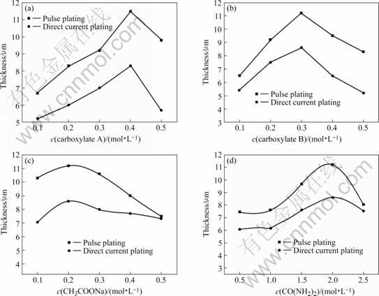
Fig.1 Effects of bath composition on thickness
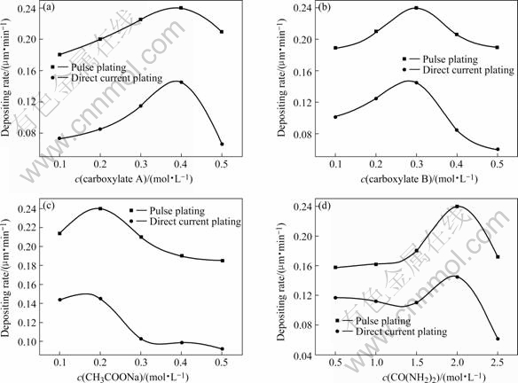
Fig.2 Effects of bath composition on electrodeposition velocity
thickness increases; while its concentration is over 0.2 mol?L-1, the thickness decreases. The reason is that acetic acid is unitary carboxylic acid. When its concentration is relatively low, its complex function is minor(the primary complexes are complex A, complex B and urea in the bath), but it can strengthen the stability of Cr3+ complex ion through cooperating with complex A, complex B and urea. When its concentration is over 0.2 mol/L, the complex function increases with the increase of sodium acetate concentration. So, the effective concentration of Cr3+ in the solution decreases, which makes it difficult to thicken. As shown in Fig.1(d), the effects of urea on thickness are different from those of complex A and B. When urea concentration increases from 0.5 mol/L to 1.0 mol/L, its thickness almost sustains unchangeable. But its thickness increases with the increase of urea concentration from 1.0 mol/L to 2.0 mol/L. When its concentration is 2.0 mol/L, the thickness of pulse electrodeposition and direct current electrodeposition Cr coatings reaches maximum of 11.2 μm and 7.1 μm, respectively. Then its thickness decreases with the increase of urea concentration, which is in agreement with the results in Ref.[12].
As shown in Fig.2, in the same bath, though pulse current density(6 A/dm2) is smaller than that of direct current density (12 A/dm2), pulse electrodeposition velocity is quicker, due to its instant high current function. Pulse electrodeposition is not only good for trivalent chromium electrodepositing, but also can increase current efficiency and lower energy waste. As shown in Figs.2(a) and (b), with the concentration increase of complex A and B, electrodeposition velocity firstly increases and then decreases. Its maximum value is 0.24 ?m/min, when concentrations of both complex A and B are 0.4 mol/L and 0.2 mol/L, respectively. This indicates that Cr3+ is not simple hydrated ion in the bath, and Cr3+ does not electrodeposit directly, but complexed Cr3+ or both complexed Cr3+ and hydrated Cr3+ electrodeposit together. Complex trivalent chromium concentration and electrodepostion velocity increase with the increase of the complex agent concentration. So, the concentration of complexed Cr3+ increases with the increase of complex agent, which makes electrodeposition velocity increase. But the complex agents can strengthen polarization function with the increase of their concentrations, which decreases electrodeposition velocity. Fig.2(c) indicates that the electrodeposition velocity increases when the sodium acetate concentration increases. While its concentration is over 0.2 mol/L, the electrodeposition velocity decreases rapidly and then almost sustains unchangeable. But the electrodeposition velocity almost does not increase when the urea concentration increases from 0.5 to 1.0 mol/L. While its concentration is over 1.5 mol/L, the electrodeposition velocity rapidly increases and then decreases(Fig.2(d)). Their effects are different from those of complex A and complex B. The reason may be that both acetate and urea can complex with Cr3+ to produce complexed Cr3+ too, but their electrodeposition reduction mechanisms in cathode are different. The complex Cr3+ must dissociate into simple hydrated Cr3+ firstly and then reduces to chromium on the cathode surface. Under a certain bath, complex A and complex B are fixed. When the acetate and urea concentrations are low, both complexed Cr3+ and hydrated Cr3+ exist in the bath. So, with the increase of concentration of urea and acetate, the electrodeposition velocity increases and then decreases. The reason is that supernumerary acetate root and urea can barricade complexed Cr3+ dissociating into simple hydrated Cr3+ ions.
3.2 Effects of operation conditions on thickness electrodeposition velocity
Figs.3 and 4 show the effects of temperature and current density on the thickness and electrodeposition velocity, respectively. As shown in Fig.3, the thickness and electrodeposition velocity of direct current plating and pulse plating Cr coating reach the maximum values at 50 ℃ and 35 ℃, respectively. When the bath temperature is over 50 ℃ and 35 ℃, their thickness rapidly decreases respectively. The reason may be that the ion migration velocity increases, which decreases concentration polarization and the reaction activation energy of Cr3+ electrodeposition decreases with the proper increase of bath temperature, thus the thickness increases. While too high temperature will strengthen the polymerization reaction between Cr3+ and OH- to form Cr(OH)3, Cr(OH)3 and Cr(OH)3 to form bridge hydroxyl, which can obstruct Cr3+ from electrodepositing. Although the increase of temperature can increase the ion migration velocity and decrease concentration polarization, the hydrogen evolution that can lower current density efficiency, increase depositing interface pH value and decrease electrodeposition velocity, can also increases.
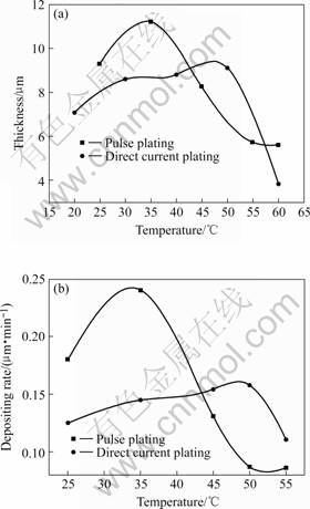
Fig.3 Effect of temperature on thickness and electrodepositing rate
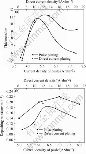
Fig.4 Effect of current density on thickness and electrodeposition velocity
As shown in Fig.4, both the thickness and electrodeposition velocity increase with the increase of current density. When direct current density is 10 A/dm2 and pulse current density is 6 A/dm2, the thickness of Cr coatings reaches maximum value, respectively. While their current density is larger than 6 A/dm2, the thickness decreases(Fig.4(a)). Their electrodeposition velocity reaches maximum values at 12 A/dm2 (0.19 μm/min) and 7 A/dm2 (0.24 μm/min) respectively. The reason is that electrodeposition velocity can increase with the increase of current density, but when the current density is too high, the Cr coating is hard to thicken due to the hydrogen evolution, which can barricade Cr3+ further to discharge. Because the current efficiency of pulse electrodeposition is higher than that of direct current, and instant high current density of pulse current is better for Cr3+ to electrodeposit, pulse electrodeposition velocity is faster than that of direct current.
3.3 Morphology and composition of chromium coating
The thickness of the Cr coating obtained from Table 1 was calculated by formula: h=(m2-m1)/(S?ρ), and its average thickness is about 11.2 μm. Fig.5 shows the SEM images of chromium coating obtained from Table 1, As shown in Fig.5, the pulse plating layer is composed of
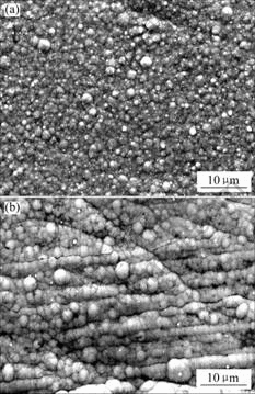
Fig.5 SEM images of electrodeposition chromium coatings: (a) Pulse electrodeposition; (b) Direct current electrodeposition
nanocrystalline with no crackle and the average grain size is less than 100 nm, but the average grain size of direct current electrodeposition coating is about 200 nm. Compared with direct current electrodeposition, pulse electrodeposition can obtain the Cr coating with finer crystallite, more smooth surface and less crackle. Figs.6 and 7 show the EDS and XRD spectra of the Cr coating obtained from Table 1. EDS spectrum indicates that the chemical composition of the coating is pure chromium and XRD spectrum indicates that the Cr deposit has face-centered cubic (fcc) structure and exhibits a (210) growth preference.
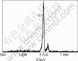
Fig.6 EDS spectrum of pulse electrodeposition coating
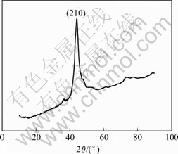
Fig.7 XRD spectrum of pulse electrodeposition coating
3.4 Electrohemical properties of Cr coating
Fig.8 shows the corrosion curves of the Cr coating obtained from Table 1. As shown in Fig.8, the corrosion potential of pulse electrodeposition Cr coating is about 100 mV higher than that of the direct electrodeposition Cr coating, and the corrosion current density and passivation current density are smaller in 1 mol/L H2SO4 solution, 3.5% NaCl solution, 10% NaOH solution, especially in 1 mol/L H2SO4 solution. The reason may be that the surface of pulse electrodeposition Cr coating is compact and no crackle is formed and the grain is fine (Fig.5). Therefore the pulse electrodeposition Cr coating owns better corrosion resistance and electrochemical properties.
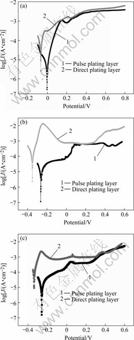
Fig.8 Corrosion curves of Cr coating: (a) 1 mol/L H2SO4 solution; (b) 3.5% NaCl solution; (c) 10% NaOH solution
4 Conclusions
1) Nanocrystalline chromium coating with 11.2 ?m thickness is obtained by pulse electrodeposition from the complex system of compound carboxylate-urea. The Cr coating possesses a smooth and clean appearance, and the grain size of Cr coating is less than 100 nm.
2) The deposits that have face-centered cubic (fcc) structure and exhibit a (210) growth preference, are pure chromium.
3) Both the electrodesposition velocity and the thickness of chromium coating exist maximum under different temperatures, current densities and concentrations of complex agent, stability agent, urea and sodium acetate.
4) Compared with direct current electrodesposition, pulse electrodesposition can obtain thick, smooth, non-crackle and fine grain chromium coating at low temperature and current density, and it owns better corrosion resistance and electrochemical properties in 1 mol/L H2SO4, 3.5% NaCl and10% NaOH bath.
References
[1] KIM M, PARK S U, KIM D Y, et al. Characterization of chromium-carbon layer fabricated by electrodeposition in trivalent chromium bath[C]//The Fifth Pacific Rim International Conference on Advanced Materials and Processing. Materials Science Forum. Beijing: Trans Tech Publications Ltd, 2005: 3823-3826.
[2] KWON S C, KIM M, PARK S U, et al. Characterization of intermediate Cr-C layer fabricated by electrodeposition in hexavalent and trivalent chromium baths[J]. Surface & Coatings Technology, 2004, 183(2/3): 151-156.
[3] SONG Y B, CHIN D T. Current efficiency and polarization behavior of trivalent chromium electrodeposition process[J]. Electrochimica Acta, 2002, 48(4): 349-356.
[4] ABD E R S S, IBRAHIM M A M, DANKERIA M M. Thin films of chromium electrodeposition from a trivalent chromium electrolyte[J]. Transactions of the Institute of Metal Finishing, 2002, 80(1): 29-33.
[5] PYE M. Alternatives to decorative hexavalent chrome electrodeposits[J]. Transactions of the Institute of Metal Finishing, 2001, 79(5): B83-B84.
[6] NAM K S, LEE K H, KWON S C, et al. Improved wear and corrosion resistance of chromium(Ⅲ) plating by oxynitrocarburising and steam oxidation[J]. Materials Letters, 2004, 58(27/28): 3540-3544.
[7] Shahin, George E. Electrodeposited alloys as a alternative for decorative hexavalent chromium[J]. Aesf Sur/Fin, 2000: 860-867.
[8] HE Xiang-zhu, ZENG Zhen-ou, PENG Rong-hua, et al. Research on the electrodeposition of amorphous Fe-Ni-Cr alloy in trivalence chromium aqueous[J]. Journal of South China University of Technology, 2003, 31(3): 15-20. (in Chinese)
[9] TZVETANKA B, MONEV M, RAICHEVSKI G S. Electrodeposition of zinc-chromium alloys[J]. UPB Scientific Bulletin, Series B: Chemistry and Materials Science, 2001, 63(3): 135-140.
[10] CHANG Y C, YEH J C, LIN C I. Process characterization of nickel-chromium alloy electrodeposition by statistical analysis[J]. Journal of the Chinese Institute of Chemical Engineers, 2001, 32(4): 351-359.
[11] SONG Y B, CHIN D T. Pulse plating of hard chromium from trivalent baths[J]. Plating and Surface Finishing, 2000, 87(9): 80-87.
[12] HE Xin-kuai, CHEN Bai-zhen, WU Lu-ye, et al. Process of pulse electrodeposition of nanocrystalline Ni-Cr alloy from trivalent chromium bath[J]. The Chinese Joural of Nonferrous Metals, 2006, 16(7): 1281-1287. (in Chinese)
[13] HE Xin-kuai. Studies of pulse electrodeposition of Cr and Cr alloys from compound carboxylate-urea complex system and blacking for Fe-Ni-Cr alloy coating[D]. Changsha: School of Metallurgical Science and Technology, Central South University, 2006: 24-42.
[14] GONG Zhu-qing, DENG Shu-hao, CHEN Wen-mi. Pulse electrodeposition of nanocrystalline nickel-iron-chromium alloy(Ⅰ)―Techniques of electrodeposition[J]. The Chinese Journal of Nonferrous Metals, 2003, 13(2): 511-516. (in Chinese)
[15] DENG Shu-hao, GONG Zhu-qing-yi. Electrochemical mechanism of trivalent chromium electrodeposition[J]. Journal of Central South University: Science and Technology, 2005, 36(2): 213-218. (in Chinese)
[16] WANG Feng, Tohru W. Preparation and characterization of the electrodeposited Fe-Cr alloy film[J]. Materials Science and Engineering A, 2003, 349(1/2): 183-190.
(Edited by CHEN Can-hua)
Foundation item: Project(06JJ30021) supported by the Natural Science Foundation of Hunan Province, China; Project(06C259) supported by the Science Foundation of Education Department of Hunan Province, China
Corresponding author: HE Xin-kuai; Tel: +86-731-8877352; E-mail: h-xk@163.com

