Enhancement of wear resistance of Ti–6Al–4V alloy by picosecond laser surface micro texturing process
来源期刊:中南大学学报(英文版)2018年第8期
论文作者:DINESH BABU P VIGNESH S VIGNESH M BALAMURUGAN C
文章页码:1836 - 1848
Key words:titanium alloy; surface texturing; Box–Benhken design; wear; coefficient of friction; optimization
Abstract: A pulsed, picosecond Nd:YAG laser with a wavelength of 532 nm is used to texture the surface of grade 5 titanium alloy (Ti–6Al–4V) for minimizing its wear rate. The wear properties of the base samples and laser surface textured samples are analyzed by conducting wear tests under a sliding condition using pin-on-disk equipment. The wear tests are conducted based on the Box–Benhken design, and the interaction of the process parameters is analyzed using response surface methodology. The wear analysis is conducted by varying the load, rotating speed of the disc, and track diameter at room temperature with a sliding distance of 1500 m. The results demonstrate that the laser textured surfaces exhibited a lower coefficient of friction and good anti-wear properties as compared with the non-textured surfaces. A regression model is developed for the wear analysis of titanium alloy using the analysis of variance technique. It is also observed from the analysis that the applied load and sliding distance are the parameters that have the greatest effect on the wear behavior followed by the wear track diameter. The optimum operating conditions have been suggested based on the results obtained from the numerical optimization approach.
Cite this article as: DINESH BABU P, VIGNESH S, VIGNESH M, BALAMURUGAN C. Enhancement of wear resistance of Ti–6Al–4V alloy by picosecond laser surface micro texturing process [J]. Journal of Central South University, 2018, 25(8): 1836–1848. DOI: https://doi.org/10.1007/s11771-018-3873-x.

J. Cent. South Univ. (2018) 25: 1836-1848
DOI: https://doi.org/10.1007/s11771-018-3873-x

DINESH BABU P1, VIGNESH S2, VIGNESH M1, BALAMURUGAN C3
1. School of Mechanical Engineering, SASTRA Deemed University, Thanjavur, Tamil Nadu 613401, India;
2. Department of Mechatronics, Bannari Amman Institute of Technology, Sathyamangalam,Tamil Nadu 638401, India;
3. Department of Mechanical Engineering, College of Engineering Guindy, Anna University, Chennai, Tamil Nadu 600025, India
 Central South University Press and Springer-Verlag GmbH Germany, part of Springer Nature 2018
Abstract: A pulsed, picosecond Nd:YAG laser with a wavelength of 532 nm is used to texture the surface of grade 5 titanium alloy (Ti–6Al–4V) for minimizing its wear rate. The wear properties of the base samples and laser surface textured samples are analyzed by conducting wear tests under a sliding condition using pin-on-disk equipment. The wear tests are conducted based on the Box–Benhken design, and the interaction of the process parameters is analyzed using response surface methodology. The wear analysis is conducted by varying the load, rotating speed of the disc, and track diameter at room temperature with a sliding distance of 1500 m. The results demonstrate that the laser textured surfaces exhibited a lower coefficient of friction and good anti-wear properties as compared with the non-textured surfaces. A regression model is developed for the wear analysis of titanium alloy using the analysis of variance technique. It is also observed from the analysis that the applied load and sliding distance are the parameters that have the greatest effect on the wear behavior followed by the wear track diameter. The optimum operating conditions have been suggested based on the results obtained from the numerical optimization approach.
Key words: titanium alloy; surface texturing; Box–Benhken design; wear; coefficient of friction; optimization
Cite this article as: DINESH BABU P, VIGNESH S, VIGNESH M, BALAMURUGAN C. Enhancement of wear resistance of Ti–6Al–4V alloy by picosecond laser surface micro texturing process [J]. Journal of Central South University, 2018, 25(8): 1836–1848. DOI: https://doi.org/10.1007/s11771-018-3873-x.
1 Introduction
The method of creating surface topography on a material is well-recognized. There are several results that confirm the substantial improvement in wear resistance when micro surface texturing is utilized under various circumstances [1]. There are a large variety of surface texturing methods such as ion beam texturing, conventional machining, and laser surface micro texturing (LSMT), which are used for creating texture patterns in micron sizes. Among these, LSMT is employed for surface structuring in tribological functions owing to its quick adaptability, cleanliness, versatility, and high precision. LSMT tends to result in the production of a number of micrometer-sized dimples of semispherical shape on sliding surfaces. It is concerned with wear and friction reducing mechanisms, thereby decreasing the contact area, collecting wear debris, varying contact position, storing of lubricant, building-up micro hydrodynamic pressure. Texturing on a material surface can decrease friction and wear by collecting the wear particles together, which has been investigated in undulated surfaces [2]. The potential benefit of LSMT is its ability to produce micro-dimples over the sliding surfaces, which are subjected to fretting. Furthermore, the entrapment of wear particles in the dimples can lead to a decrease of approximately 84% in the contact resistance of the micro dimpled surface as compared with normal smooth surfaces [3, 4].
Ti–6Al–4V alloy has been observed to exhibit a high strength-to-weight ratio, high toughness, exceptional resistance to corrosion, and ability to withstand extreme temperatures [5]. However, the high material and processing cost involved limits its use in military applications, medical devices, spacecraft, and aircraft. Although titanium alloys have excellent mechanical and chemical properties, their applications are restricted owing to their poor wear resistance, particularly in dry sliding applications. HU et al [1] investigated the influence of dimple concentration on the frictional performance of a titanium alloy under sliding conditions. They observed the dimpled surface with a high texture density and low coefficient of friction (CoF) at a minimal applied load and speed. MARESSA et al [6] analyzed the influence of laser texturing on a titanium alloy and found that laser texturing provides up to eightfold higher shear strength as compared with non-textured surfaces. HE et al [7] analyzed the effect of laser texture patterns with different densities on a titanium alloy surface in dry sliding and lubricated conditions. They achieved a reduction in friction by collecting the wear particles in the dimples during sliding motions. PREM et al [8] investigated the wear mechanism of composite coated Ti–6Al–4V alloy surfaces in sliding conditions. They observed the improved bonding strength of the coating through surface texturing and portrayed a substantial decrease in the wear. PFLEGING et al [9] characterized a laser textured titanium alloy with line and dimple profiles. They showed that better refinement in the microstructure in the laser textured surface as compared with non-textured surface. RODRIGO et al [10] analyzed the effect of dimple structured surfaces on cutting tools in order to reduce the friction between the tool rake face and chips. They observed that the concentration of the dimples is an important factor to be considered in friction-related research.
Although there are several research works related to the wear analyses of various materials that are surface processed using LSMT, the research performed on the wear behavior of laser textured titanium alloys operated in dry sliding conditions at room temperature is limited. This research mainly focuses on the wear analysis of a laser surface textured titanium alloy Ti–6Al–4V in dry sliding conditions and the development of a regression model for the wear analysis. In the experimental work, initially, the Ti–6Al–4V samples are surface textured using the LSMT technique. Wear tests are then performed to evaluate the wear rate and CoF by varying the input parameters in the response-surface-methodology-based (RSM-based) Box–Benhken design (BBD) using design of experiments (DOE).
The size and depth of the dimple and density are the most important factors that affect the wear rate and CoF. The contact area between the sliding surfaces is dependent on the dimple size, and it acts as a reservoir for collecting the wear debris during sliding conditions. The density variation also plays an important role in the sliding wear. As the dimple density is higher, the contact area is found to be less. In this work, the size, depth, and density of the dimple are optimum in order to minimize the wear rate and are selected based on the initial trials conducted with different laser power and scanning speeds.
The results obtained are analyzed using RSM to establish a regression model in order to determine the most significant factor that influences the wear rate and CoF. The direct and combined effects of the parameters on the output responses are investigated using RSM [11–13]. From this statistical analysis, the optimum operating parameters can be suggested for the laser surface textured titanium alloy Ti–6Al–4V operated in dry sliding conditions.
2 Methodology
2.1 Design of experiment and RSM
DOE is a systematic, scientific method that is preferred for planning the experiment and determining the relationship between the parameters influencing the process and its output. RSM is a compilation of statistical and mathematical techniques for developing regression models and is used to determine the optimal result that would produce the maximum level of responses; its objective is to optimize the output response, which is influenced by some of the input parameters. It is used to develop the regression models using an analytical technique called analysis of variance (ANOVA), and these models establish the connection between the input parameters and output variables. We have adopted BBD in this research, which is the most appropriate approach for three input factors with three different levels.
2.2 Preparation of specimen
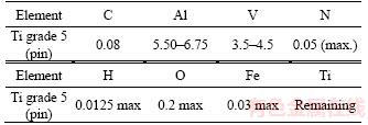
Ti–6Al–4V alloy is used as the study material for this experimental work. The chemical composition of the Ti–6Al–4V alloy is presented in Table 1. The pin samples (Ti–6Al–4V) are fabricated to have a size of f8 mm and length 50 mm. The head of the pin shown in Figure 1 is of the plane surface type. The averaged friction coefficient is calculated, and the necessary graph is plotted with respect to the load and sliding distance. The hardness of the pin material is approximately HV0.5 320. Initially, the surface of the pin is polished using various grades of Si–C emery sheets varying from coarse to fine grades. These polished pin surfaces are further refined to a mirror-like finish using a disc polishing machine with the use of alumina powder and water.
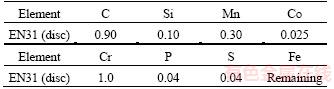
The discs have been fabricated from EN31 material to have a diameter of 60 mm and thickness of 20 mm. The chemical composition of the disc material is provided in Table 2. The hardness of the heat-treated disc has been observed to be HV0.5 800.
Table 1 Chemical composition (wt%) of pin material
2.3 Experimental procedure
After the preparation of the specimens, LSMT is performed on the surface of the pin using a 3-W neodymium yttrium-aluminum-garnet (Nd:YAG) laser with a wavelength of 532 nm and repetition rate of 45 kHz. A laser beam of diameter 60 μm in the focused condition is used with output energy of 60 μJ. During the LSMT, the pin is kept stationary over the laser machine table, and the laser head is manipulated over the surface of the pin according to the dimple pattern and number of passes. The manipulation of the laser head is performed by a computer numerical control (CNC) arrangement connected to the laser machine. The schematic of the picosecond laser surface texturing arrangement is shown in Figure 2.
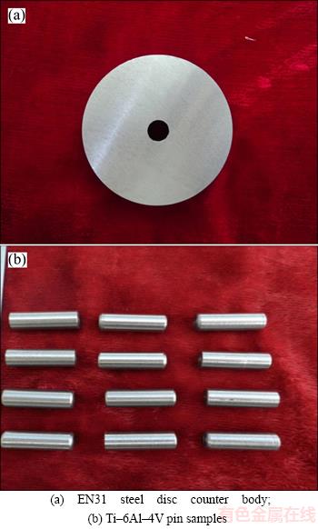
Figure 1 Specimen prepared for pin-on-disc dry sliding wear test:
Table 2 Chemical composition (wt%) of disc material
The micro texturing is performed with an Nd:YAG laser source (shown in Figure 3) with a laser beam velocity of 2.5, 5.0, and 7.5 mm/s over the surface of the pin material. The dimple pattern was considered a square with a center-to-center distance of the dimples of 160 μm both in the X and Y directions. The profiles of the textures are similar to the entire diameter range and be similar to the shape of a hemisphere indented into the surface.
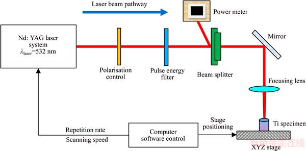
Figure 2 Schematic of picosecond laser surface texturing setup

Figure 3 Nd:YAG laser texturing machine
The debris formed during the texturing process is cleared with acetone by gently applying it over the surface of the pin material.
2.4 Sliding wear test
A pin-on-disc apparatus is used to test the specimens of both the surface textured and base material for its wear behavior under sliding conditions. A strain gauge is attached to the wear testing machine to measure the frictional forces developed during the test. A computer that has the wear analysis software installed is connected to the controller of the wear testing machine to store the variable output responses at regular intervals. The test was performed as per the ASTM G99-05 standard with the pin as the substrate. The mass of the pin samples is measured before and after the wear test using a digital mass balance with an accuracy of 0.001 g.
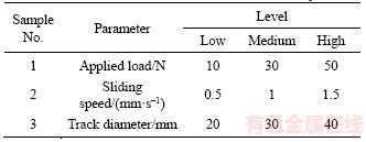
The wear test to be performed is designed using the RSM-based Box–Benhken method with statistical software. The applied load, sliding speed, and wear track diameter are the three input parameters. The RSM approach designs the experiment levels to be performed at low, medium and high levels. The experiment levels and input variables for the wear test are presented in Table 3.
Table 3 Parameters and levels used for wear analysis
The wear test is performed according to the experimental parameter window established from the design expert software. The test is performed for both the textured and base materials by considering the sliding distance to be constant. The wear test is performed based on the ASTM standard with a tribometer with the pin-on-disc configuration. In order to establish more contact with the counter surface, the samples are polished with emery sheets of various grades.
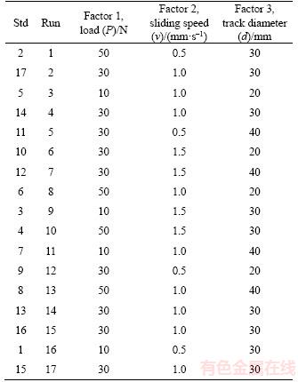
With the help of the design expert software, the input parameter ranges considered for the analysis are entered and simulated. The resultant trial matrix obtained is given in Table 4.
Table 4 Design matrix for wear analysis
A digital balance is used to determine the volume loss of the samples in each test. The strain gauge with an S-configuration is used to calculate the frictional force.
3 Results and discussion
From the initial trials conducted for three different laser beam travel speeds (2.5, 5.0, and 7.5 mm/s), the lower one (2.5 mm/s) is selected for further wear analysis. This low speed allows for a greater interaction time of the laser beam with the material surface and results in a higher dimple depth of 30 μm and diameter of 90 μm with a dimple density of 20%. These high-density dimples formed at a lower scanning speed reduce the contact area with the disc material during the sliding, the friction, and the wear rate.
3.1 Laser texture pattern
The scanning electron microscopy (SEM) graph of the laser textured sample with a travel speed of 2.5 mm/s is shown in Figure 4 along with the dimensions of the dimples. Before the SEM analysis, the textured samples are polished for a few seconds using a disc polishing machine in order to remove the melted region around the dimples. The area surrounding the dimple is the region affected by the laser heat and comprises partially melted metal. The SEM analysis confirms the regular square pattern and dimple sizes formed with the selected laser parameters. The average dimple diameter obtained for the selected parameter is f90 μm with a center-to-center distance of 160 μm in the X and Y directions.
3.2 Coefficient of friction and wear rate
The sliding wear tests are conducted on the samples (both textured and non-textured) according to the trial matrix obtained from the BBD using the design expert software. The measured and calculated output values from the wear tests are shown in Table 5.
The comparative study shown in Figure 5 illustrates the difference in CoF and wear rate of the samples before and after the laser texturing as a function of the load. In these graphs, it is observed that the CoF and wear rate increase with the increase in the load from 10 N to 50 N for the samples tested with a sliding speed of 1.0 mm/s and sliding distance of 1500 m. BUDZYNSKI et al [14] inspected the dry sliding behavior of the titanium alloy with the counter surface and found the CoF to be 0.15 to 0.30. This substantiates the interaction of the pin surface with that of the disc material considered in this research. The CoF monitored in this study for various loading conditions and sliding speeds is in the range of 0.2600 and 0.3250 for textured samples, which is less than that of the non-textured samples in the range of 0.35 and 0.40.
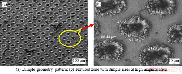
Figure 4 Scanning electron micrographs of laser surface textured Ti–6Al–4V sample surface:
Table 5 Coefficient of friction and wear rate of test samples
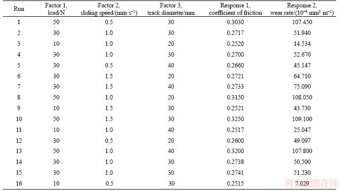
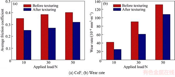
Figure 5 Wear analysis of samples before and after texturing in various loading conditions and at constant wear track diameter of 40 mm, sliding speed of 1 mm/s, and sliding distance of 1500 m:
The wear rate is estimated from the amount of material that is detached from the pin samples. The increase in the applied load in turn tends to increase the wear rate of both the laser textured and as-received surfaces. The minimum wear rate of 7×10⁻⁴ mm3/m is measured for the load of 10 N, sliding speed of 0.5 mm/s, and wear track diameter of 30 mm. The wear life of the textured samples is approximately 30% superior to the as-received sample surfaces at an applied load of 10 N. The same trend has been observed for the other load levels. Upon considering all the load levels, the textured surfaces reveal a comparatively lower CoF and wear rate, which is probably due to the reduced contact area and debris behavior, which has been collected within the texture regions called micro dimples.
The SEM morphology of the worn-out surfaces for both the non-textured and laser textured pin specimens at the load of 50 N is shown in Figure 6. The sliding directions are indicated for the non-textured and textured samples in Figures 6(a) and (c) respectively. The SEM analysis of the pin surfaces for the sliding wear condition provides a significant means of disseminating the wear behavior of Ti–6Al–4V in an accurate manner. It also reveals that the wear debris produced in the as-received material is higher than that in the laser textured specimens. The adhesive wear behavior is observed in the as-received samples (Figure 6(c)) with some minor cracks. In the textured samples, owing to the reduced contact area due to the dimples, the wear damage is comparatively less, and Figure 5(d) confirms the formation of micro grooves and some wear debris.
3.3 Interaction effect of process parameters on CoF and wear rate
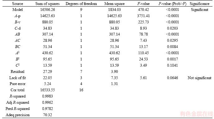
The ANOVA analysis has been performed for the output responses obtained for the given range of input parameters. The ANOVA analyses for the responses CoF and wear rate are shown in Tables 6 and 7 respectively. The mathematical relations formulated for the CoF and wear rate with the input parameters are shown in the regression Eqs. (1) and (2), respectively.
The ANOVA results in Table 6 prove that the model obtained is considerable the “Model F-value” is 375.14, and the possibility of Model F-value due to noise is only 0.01%. The values of “Prob>F” are less than 0.05, and thus the model terms A, B, C, AB, A2 and B2 are significant. When we look at the “Lack of fit F-value” of 0.94, it is clear that it is not significant relative to the pure error. This shows that there is only a possibility of 50.09 % that could be due to noise. Thus, it is clear that when the lack of fit is not significant, the model is said to be fit. After comparing the “Pred R-squared” of 0.9844 and “Adj R-squared” of 0.9953, it is confirmed that they are in reasonable agreement with each other. “Adeq precision” gives the signal-to-noise ratio, and it is enviable if the ratio is greater than 4. The ratio obtained in the model is found to be 58.446, which indicates an adequate signal. Therefore, it is evident that the model can be used to pilot the design space.
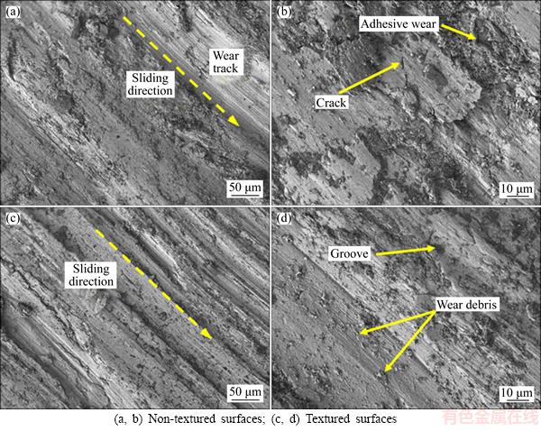
Figure 6 SEM images of worn-out surfaces at applied load of 50 N:
Table 6 ANOVA analysis for coefficient of friction
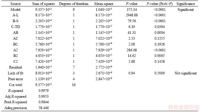
Table 7 ANOVA analysis of wear rate
CoF=0.2307-1.194×10⁻³ P+0.02647v+9.865×10⁻⁴d+5.35×10⁻⁴Pv+6.625×10⁻⁶Pd–2.4×10⁻⁴vd+3.43063×10⁻⁵P2-0.01241v2–1.3275×10⁻⁵d2 (1)
Figure 7 illustrates the variation in the CoF as a function of the load and speed in a contour and surface plot for the textured sample with a wear track diameter of 40 mm. The contour plot indicates a higher CoF formed when the applied load and sliding distances are higher at 50 N and 1.5 mm/s respectively. The CoF observed is low for the minimum conditions of a load of 10 N and speed of 0.5 mm/s. It is observed from the ANOVA analysis that the influence of the track diameter in the wear behavior is less as compared with that of the other parameters.
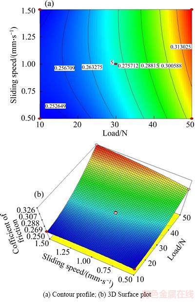
Figure 7 Influence of load and sliding speed on coefficient of friction with a constant wear track diameter of 40 mm:
The ANOVA study in Table 7 confirms that the model obtained is significant as the “Model F-value” is 470.42, and the possibility of the “Model F-value” due to noise is only 0.01%. The values of “Prob>F” are less than 0.05, and thus, the model terms are significant. The “Lack of Fit F-value” is 5.61. This clearly indicates that the lack of fit is not significant. This shows that there is only a possibility of 6.46% that could be due to noise. Thus, it is clear that when the lack of fit is not significant, the model is said to be fit.
Wear rate=1.66350+1.90081P–12.36v–1.18227d-0.87627Pv–0.013454Pd+0.7165vd+0.025283P2+19.065v2+0.017967d2 (2)
The wear rates of the textured samples are illustrated in Figure 8. Upon observing the results in Figures 7(a) and (b), the increase in the load and speed, which results in an increases in the wear rate owing to the higher frictional force induced in the high load and speed conditions, are evident. The ANOVA results demonstrate that the maximum wear rate in the textured sample is attained at a 50-N load with a speed of 1.5 mm/s. When we compare these results with those of the as-received samples, the wear rate observed in the textured pin surface is approximately 30% less, which reveals the influence and importance of the surface texturing in the Ti–6Al–4V material for sliding contact applications.

Figure 8 Influence of load and sliding speed on wear rate with constant wear track diameter of 40 mm:
The cube plot in Figure 9 shows three continuous factors (load, sliding speed, and track diameter). The BBD comprises 15 runs, of which, we considered 12 runs for analyzing all the possible combinations of low and high levels for each pair of variables (with the third variable at the center) with three center points. These designs can be rotated and require three levels (coded as –1, 0, and +1) for each factor. The cubic plot shows the position of the design points for all the selected variables.
4 Optimization of wear parameters
The foremost aim of this research is to minimize the wear rate of Ti–6Al–4V and determine the optimum parameters of the developed regression models. A multiple-response technique called the desirability approach has been used to combine the responses into an overall desirability function, which is a dimensionless number between 0 and 1. The optimization was performed using the desirability approach in order to determine the optimized input solutions that would provide the desired output responses. The output responses such as CoF and wear rate are to be minimized for the combination of input process parameters such as load, speed, and track diameter.
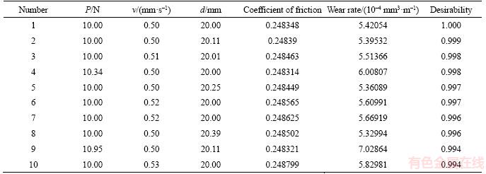
The constraints in the study are shown in Table 8. The objective is to determine the optimal solutions such that it would minimize the wear rate and CoF. The optimized solutions are shown in Table 9. The predicted optimal results are p=10 N, v=0.5 mm/s, and d=20 mm. It is also observed from the optimized solution that the desirability value for the first 10 solutions is approximately 1, which confirms that the developed regression model is more suitable for predicting optimum results. The coefficient of friction and wear rate values are very close in all the 10 solutions obtained with small deviations in the 4th and 9th numbers of wear rate owing to a slight increment in load.
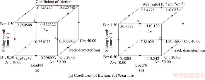
Figure 9 Cube plot showing output response:
Table 8 Constraints involved in optimization
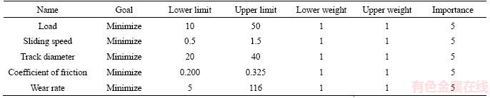
Table 9 Optimized solutions
Figures 10(a) and (b) show the optimum values of the input parameters for the given range of variables and criteria. X1 (10 N) and X2(0.5 mm/s) in the plots represent the optimum load and sliding speed, respectively, for the constant wear track diameter of 20 mm. The red color in the plots indicates higher coefficient of friction and wear rate regimes, which occur for higher load (approximately 50 N) and sliding speed (1.5 mm/s) conditions.
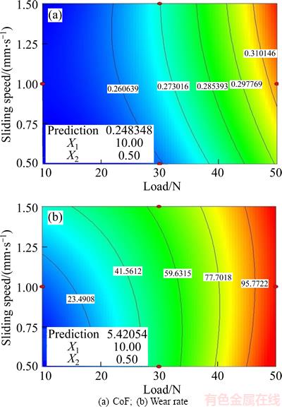
Figure 10 Optimized values of input parameters for output responses for track diameter of 20 mm:
The bar graph generated (shown in Figure 11) using an optimization module in the design expert software provides the combined desirability value of 1 for the selected combined objective with the required constraints. It is clear that the overlay graph optimization permits a direct selection of the optimum regions according to the given criteria. The output of the optimization is the overlay graph. This type of graph is useful for selecting the values of the wear parameters that would facilitate certain output responses for the selected material. The yellow region in the overlay graph shown in Figure 12 is the region that would meet up the given criteria.
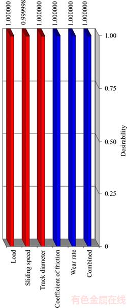
Figure 11 Individual and combined desirability
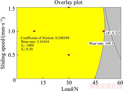
Figure 12 Overlay plot showing optimized solutions
5 Conclusions
Based on the experimental analysis, the influence of the laser texturing on the wear rate and CoF is observed and discussed. The optimal process parameters are identified using the numerical optimization technique.
1) The titanium alloy in the as-received condition exhibits a higher mass loss and has a higher coefficient of friction as compared with the samples obtained after the laser surface texturing process. The wear parameters such as load, speed, and track diameter are proportional to the wear rate and coefficient of friction. The wear resistance is enhanced reasonably for the laser textured surfaces at all the considered applied loads.
2) The optimum combination of the parameter values is a load of 10 N, sliding speed of 0.5 mm/s, and track diameter of 20 mm, and the corresponding wear rate and CoF values are 5.42054 mm3/m and 0.2483 respectively.
3) The samples are processed at various laser travel speeds, and the samples processed with a lower laser travel speed exhibit a higher ablation rate resulting in high-density dimples. This higher ablation rate results in lower friction in the material in sliding applications owing to a reduction in the contact area. These results clearly show that the use of suitable surface texturing with appropriate wear parameters can efficiently minimize the wear rate of a titanium alloy, which would be favorable for its application in aerospace and biomedical engineering.
4) Furthermore, a change in the texture pattern to hexagonal or triangular, etc., and in the texture density would definitely result in a change in the wear behavior. Therefore, in future, researchers can focus on this area to develop the surface properties of titanium alloys.
Acknowledgement
The authors are grateful to Dr. Ing. M. Duraiselvam, Head of the Production Department at the National Institute of Technology, Tiruchirappalli, India, for the support of laser texturing process. We would also like to thank SASTRA University for the valuable help and support provided.
References
[1] HU Tian-chang, HU Li-tian, DING Qi. Effective solution for the tribological problems of Ti–6Al–4V: Combination of laser surface texturing and solid lubricant film [J]. Surface and Coating Technology, 2012, 206: 5060–5066.
[2] TIAN H, SAKA N, SUH N P. Boundary lubrication studies on undulated titanium surfaces [J]. Tribology Transactions 1989, 32(3): 289–296.
[3] VARENBERG M, HALPERIN G, ETSION I. Different aspects of the role of wear debris in fretting wear [J]. Wear 2002, 252: 902–910.
[4] VOLCHOK A, HALPERIN G, ETSION I. The effect of surface regular micro-topography on fretting fatigue life [J]. Wear, 2002, 253: 509–515.
[5] XU Pei-quan. Microstructure characterization of Ti-6Al-4V titanium laser weld and its deformation [J]. Transaction of Nonferrous Metal Society of China, 2012, 22: 2118-2123.
[6] MARESSA P, ANODIO L, BERNASCONI A, DEMIR A G, PREVITALI B. Effect of surface texture on the adhesion performance of laser treated Ti6Al4V alloy [J]. Journal of Adhesives, 2015, 91: 518–537.
[7] HE Dong-qing, ZHENG Shao-xian, PU Ji-bin, ZHANG Guan-gan, HU Li-tian. Improving tribological properties of titanium alloys by combining laser surface texturing and diamond-like carbon film [J]. Tribology International, 2015, 82: 20–27.
[8] MUTHUVEL P A, RAJAGOPAL R. Influence of surface texture on tribological performance of Al–Cr–N nano composite coated titanium alloy surfaces [J]. Proceedings of Institution for Mechanical Engineers Part J: Journal of Engineering Tribology, 2013, 227(10): 1157–1164.
[9] PFLEGING W, KUMARI R, BESSER H, SCHARNWEBER T, MAJUMDAR J D. Laser surface textured titanium alloy (Ti–6Al–4V): Part 1–Surface characterization [J]. Applied Surface Science, 2015, 355: 104–111.
[10] STOETERAU R L, JANSSEN A, MALLMANN G. Analysis of dimple textured surfaces on cutting tools [J]. Journal of Brazilian Society for Mechanical Science and Engineering, 2016, 39(10): 1–8. DOI: 10.1007/s40430-016-0692-6.
[11] SHUKOR S, ANAND T J S, AMMAR. DOE based statistical approaches in modeling of laser processing– Review & suggestion [J]. International Journal of Engineering and Technology, 2010, 10(4): 1–7.
[12] STOTT F H, LIN D S, WOOD G F, STEVENSON C W. The tribological behavior of nickel and nickel chromium alloys at temperatures from 20 °C to 800 °C [J]. Wear, 1969, 36: 147–174.
[13] DINESH BABU P, BUVANASHEKARAN G, BALASUBRAMANIAN K R. Experimental investigation of laser transformation hardening of low alloy steel using response surface methodology [J]. International Journal of Advanced Manufacturing Technology, 2013, 67: 1883–1897.
[14] BUDZYNSKI P, YOUSSEF A A, SIELANKO J. Surface modification of Ti–6Al–4V alloy by nitrogen ion implantation [J]. Wear, 2006, 261: 1271–1276.
(Edited by YANG Hua)
中文导读
皮秒激光微变形工艺增强Ti–6Al–4V合金的耐磨性
摘要:采用波长为532 nm的脉冲皮秒Nd:YAG激光器对5级钛合金(Ti–6Al–4V)表面进行织构,使其磨损率降至最低。通过在滑动条件下用盘式销状设备进行磨损试验,分析了基体试样和激光表面织构试样的磨损性能。采用Box–Benhken设计方法进行了磨损试验,并采用响应面法分析了工艺参数之间的相互作用。通过改变载荷、圆盘转速和轨道直径,在室温下,以1500 m为滑动距离,进行了磨损分析。结果表明,与非织构表面相比,激光织构表面具有较低的摩擦系数和良好的耐磨性能。利用方差分析方法建立了钛合金磨损分析的回归模型。分析还发现,载荷和滑动距离是对磨损性能影响最大的参数,其次是磨损径迹直径。根据数值优化的结果,提出了优化的操作条件。
关键词:钛合金;表面变形;箱体设计;磨损;摩擦系数;优化
Received date: 2017-03-27; Accepted date: 2017-10-14
Corresponding author: DINESH BABU P, PhD, Senior Assistant Professor; Tel: +91-9442451792; E-mail: dineshbabu@mech. sastra.edu, pdineshbabu81@gmail.com; ORCID: 0000-0002-9606-3289

