J. Cent. South Univ. (2016) 23: 440-448
DOI: 10.1007/s11771-016-3089-x

Failure mechanism of bolting support and high-strength bolt-grouting technology for deep and soft surrounding rock with high stress
LI Shu-cai(������)1, WANG Hong-tao(������)1, 2, WANG Qi(����)1, 3, JIANG Bei(����)1,
WANG Fu-qi(������)3, GUO Nian-bo(���)3, LIU Wen-jiang(���Ľ�)3, REN Yao-xi(��Ңϲ)4
1. Research Center of Geotechnical and Structural Engineering, Shandong University, Jinan 250061, China;
2. School of Civil Engineering, Shandong Jianzhu University, Jinan 250101, China;
3. Post-Doctoral Scientific Research Station, Yankuang Group Company Limited, Zoucheng 273500, China;
4. Liangjia Coal Mine, Longkou Coal-Electric Company Limited, Longkou 265700, China
 Central South University Press and Springer-Verlag Berlin Heidelberg 2016
Abstract: In deep underground mining, the surrounding rocks are very soft with high stress. Their deformation and destruction are serious, and frequent failures occur on the bolt support. The failure mechanism of bolt support is proposed to solve these problems. A calculation theory is established on the bond strength of the interface between the anchoring agent and surrounding rocks. An analysis is made on the influence law of different mechanical parameters of surrounding rocks on the interfacial bond strength. Based on the research, a new high-strength bolt-grouting technology is developed and applied on site. Besides, some helpful engineering suggestions and measures are proposed. The research shows that the serious deformation and failure, and the lower bond strength are the major factors causing frequent failures of bolt support. So, the bolt could not give full play to its supporting potential. It is also shown that as the integrity, strength, interface dilatancy and stress of surrounding rocks are improved, the bond strength will increase. So, the anchoring force on surrounding rocks can be effectively improved by employing an anchoring agent with high sand content, mechanical anchoring means, or grouting reinforcement. The new technology has advantages in a high strength, imposing pre-tightening force, and giving full play to the bolt supporting potential. Hence, it can improve the control effect on surrounding rocks. All these could be helpful references for the design of bolt support in deep underground mines.
Key words: high stress; soft rock; bolting support; interface dilation; failure mechanism; high strength; bolt-grouting technology
1 Introduction
As a support technology in underground mining engineering, bolting has been used for more than 100 years since 1912 in Germany [1�C2]. In roadway excavation, it can provide radial constraint for fractured surrounding rocks in the supporting range to install bolts and impose certain pre-tightening force on the surface of surrounding rocks. It increases the strength of surrounding rocks and combines surrounding rocks with the bolts. Therefore, they form a self-bearing structure, resist jointly the deformation and failure of surrounding rocks outside the loosing circle, and maintain the security and stability of roadways.
However, more and more mines have been excavated in deep underground today. The deformation and failure of surrounding rocks are serious under a high in-situ stress. In particular, when the geological conditions of the roadway are poor, the surrounding rock is extremely soft and fractured with a large failure range, and it fails to provide support components (including the bolt and anchor cable) with an effective and stable anchoring foundation. This situation easily causes the frequent failure of bolting support and cannot give full play to the bolt supporting potential; thus, it further increases roadway supporting difficulties and even security incidents such as roof falling, and greatly threatens the safety production of mines.
Scholars have conducted many studies on the function and failure mechanism of bolt support for soft and fractured surrounding rocks. In the bolting function mechanism, HOU and GUO [3] studied the strengthening effect of roadway bolting support on the peak and residual strength of rock within the anchoring range through laboratory tests and theoretical analysis; INDRARATNA [4] studied the fracture mechanism of surrounding rock in the circular roadway under bolting support by conducting model tests; INDRARATNA and KAISER [5], LI and STILLBORG [6], BOBET and EINSTEIN [7], and CAI et al [8] proposed the mechanical analysis model of surrounding rocks under bolt support based on the elastic-plastic theory. As for the failure mechanism of bolting support, KANG et al [9] analyzed the breakup mode and reason of non-full-length anchoring bolt based on field monitoring; they proposed related improvement measures and conducted field application; LI [10] believed that bolt breakup in high- stress surrounding rock was caused by the joint action of tensile and shear stress based on field measurement and analysis; BLANCO et al [11] studied the mechanical failure behaviors on the bolt/grout interface through laboratory pull-out tests; KILIC et al [12�C13] studied the influence law of the bolt ultimate bearing capacity affected by factors including the shape, diameter and length of the bolt body, as well as grouting materials; REN et al [14] and CAO et al [15] studied the bolting failure mechanism by establishing a theoretical analysis model. The above researches mainly focused on the bolt body breakup and the bonding failures on the bolt/grout interface. But the poor capacity and failure of bonding on the grout/rock interface are common in the extremely soft and fractured surrounding rock, and should not be neglected. Besides, there are many other factors causing bolt support failure due to complex and geo-mechanical environment changes of deep surrounding rocks. So, the failure mechanism needs to be further discussed.
In this work, the locomotive maintenance chamber of the 2# main roadway in the south of Zhaolou Coal Mine in Juye Mine Area is taken as an example. The surrounding rocks in this roadway are typically deep, soft and fractured rocks with high stress. Based on the early field monitoring, the failure mechanism of the bolt support is analyzed in depth. A calculation theory is established on the bond strength on the interface between the anchoring agent and surrounding rocks. The influence law of different mechanical parameters of surrounding rocks on the interfacial bond strength is also discussed. Based on the research, a new high-strength bolt-grouting technology is developed and applied on site. Besides, some helpful engineering suggestions and measures are proposed.
2 Failure mechanism study on bolting support
2.1 Project overview
Located in the central part of Juye Coal Field, Zhaolou Coal Mine is developed by vertical shaft with a designed production capacity of 3.0 Mt/a and the mining level of �C860 m. The stratum in this area is a monoclinic structure with an overall trend of north to south and east. It has secondary level wide and gentle folds and a certain number of faults.
Located in the southwest of the mine, the locomotive maintenance chamber of 2# main roadway is designed 174 m long to serve for 60 years. It is used mainly for the maintenance needs of trackless tire vehicles and diesel locomotives. The surrounding rocks in the roadway are mainly composed of the soft shale. During tunneling, the main exposure appears on fine and medium sandstone above 3# coalseam; a layered structure with the fine sandstone is on the roof; some areas are filled with calcite veins, and the floor is composed of medium sandstone. With the complex field geological structure, more vertical tensile fractures develop and the rock stratum is fractured. The maximum principal stress in the in-situ stress field is the horizontal stress ranging from 32.4 MPa to 34.6 MPa in a direction basically parallel with the locomotive maintenance chamber. The maximum horizontal principal stress is 1.35�C1.36 times the vertical stress and 1.75�C1.90 times the minimum horizontal stress.
The section shape of the locomotive maintenance chamber is a vertical-wall semicircular arch. The dimensions of the net section are 6000 mm��4900 mm and the vertical wall is 1900 mm high. The bolt-shotcrete support is designed in the original supporting scheme. High-strength steel bolts adopted are ��22 mm��2400 mm; they are left lateral threaded without longitudinal reinforcement threads and anchored by one K28100 resin stick with inter-row space of 800 mm��800 mm. High- strength pre-stressed steel strands of ��22 mm��6200 mm are adopted as the anchor cables, and they are anchored by two K25100 resin sticks, three in each row with inter- row space of 2000 mm��2400 mm. The pre-tightening torques of the roof bolt and side bolt, and the force of the anchor cable are 120 N��m, 100 N��m, and 100 kN, respectively. C25 concrete of 100 mm thick is sprayed on the roadway surface.
2.2 Monitoring analysis on deformation characteristic of surrounding rock and supporting component force
To analyze the deformation and failure of soft surrounding rocks and the supporting component stress in site, monitoring sections are set in the testing part of the roadway of the original support scheme. They are for roadway surface convergence, bolt and anchor cable force. As shown in Fig. 1, convergence monitoring sections on the surrounding rock surface include measuring point D (middle roof), the measurement points L (left side), measuring point R (right side), and measuring point F (floor); bolt force monitoring sections include Bolt 1 (left side), Bolt 2 (middle roof), and Bolt 3 (right side); anchor force monitoring sections include Cable 1 (left shoulder), Cable 2 (middle roof), and Cable 3 (right shoulder).
Figures 2 and 3 show the early convergence deformation of field surrounding rock and force monitoring results of supporting components.

Fig. 1 Section design drawing in original supporting scheme (Unit: mm)
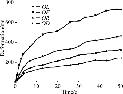
Fig. 2 Monitoring curves of roadway convergence deformation

Fig. 3 Force monitoring curves of supporting components
1) With the original scheme, within 10 days after roadway excavation, the deformation of surrounding rock is fast and then tends to be gentle without an obvious stabilizing stage. This means that the deformation continues to increase. The floor heave is the main deformation and failure site of the roadway. On the 50th day of excavation, the floor heave is 728 mm; roof subsidence is 463 mm; side-to-side convergence is 569 mm; moreover, the field shotcrete layer cracks seriously. The deformation and failure severely affect the normal use of the field roadway.
2) Due to their small initial pre-tightening force (20�C30 kN), the bolts are generally under small force. On the 50th day of excavation, the average force is only 52.3 kN, far below the bolt yield strength; but the anchor cables are generally under a large force with the maximum of 281 kN. However, the anchor cables on site often slip, which decreases the force on them and further intensifies the deformation and failure of surrounding rocks in the roadway.
Based on field geological conditions, an analysis is made on the field monitoring results. It is shown that the serious deformation and failure of the surrounding rocks, the small forces or frequent failures on supporting components are mainly caused by the following aspects: (1) The field surrounding rocks are mainly composed of the soft shale with low self-strength and many fractures. The action of high-stress in the deep underground further intensifies the deformation and failure of surrounding rocks and makes surrounding rocks extremely soft and fractured. With a poor self-bearing capacity, the surrounding rocks show a large failure range even exceeding the bolt length to some extent. (2) The field surrounding rocks are loose, soft and fractured and therefore fail to provide a stable anchoring foundation for supporting components. This also continuously decreases the bond strength between anchoring agents and surrounding rocks and causes bonding failure, small force or force decrease on supporting components. As a result, the supporting components fail to give full play to their potential and also the deformation and failure of surrounding rock are intensified. (3) In the anchoring support engineering on site, the hole collapses tend to occur in the surrounding rock borehole. As a result, the filling between surrounding rocks and the bolt, anchor cable and anchoring agent is not dense, which further decreases the anchoring force of the bolt and anchor cable; so they hardly bear larger loads. Meanwhile, the restriction on field construction equipment makes the initial pre-tightening force of the bolt small and the active support effects of surrounding rocks poor. This is another main factor causing serious deformation and failure of surrounding rocks.
2.3 Theoretical analysis on failure mechanism analysis on bolting support
In deep, soft and fractured surrounding rocks under high stress, the failure of supporting components and the deformation and failure of surrounding rocks are complementary. The interaction between the bolt support components and soft surrounding rocks needs to be further studied and discussed. First, the failure mechanism of bolt support components should be defined before some specific control measures are proposed.
The bolting failure usually occurs in the following positions: (1) in the bolt, (2) in the grout, (3) in the rock, (4) at the bolt/grout interface, (5) at the grout/rock interface, and (6) a combination of these failure modes [14�C15]. In the current deep mining engineering, supporting components are usually anchored by high- strength resin sticks. However, when surrounding rocks are loose, soft and fractured, the bonding capacity between the anchoring agent and surrounding rocks is poor. Therefore, this interface is a weakness of the entire bolting support system and should be emphasized in the design of the bolt support, which determines the bearing capacity of the bolt. Moreover, the deformation of the surrounding rocks has timeliness; therefore, the bonding failure between the anchoring agent and surrounding rocks does not occur instantly; it occurs gradually along with the deformation of the surrounding rocks. YOU et al [16] classified this interface bonding failure into four stages: elastic deformation, slip deformation, debond appearance and development, and complete debond. They indicated this interface was on one side of the surrounding rocks and the interface bonding capacity mainly depended on the strength of the surrounding rocks [17].
In the gradual failure of the interface between the anchoring agent and the surrounding rocks, as shown in Fig. 4, the relative shear slip between them makes the failure interface dilatancy, and it imposes normal dilatation stress on the surrounding rocks. The dilation stress can improve the shear capability of the anchorage body interface. YOU and ZHAN [17] also verified this phenomenon through laboratory pull-out tests.
The interface bonding failure between the anchoring agent and the surrounding rocks is assumed to meet the Mohr-Coulomb strength criterion. According to non- associated flow rule of this criterion [18] and based on the plastic flow direction of the interface layer in Fig. 4,the following formula can be obtained:
 (1)
(1)
where v(z) is the interface normal displacement; u(z) is the interface relative shear displacement; f��is the interface dilatancy angle.
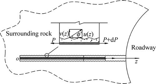
Fig. 4 Failure analysis model of interface between anchoring agent and surrounding rock
Meanwhile, the interface dilation effect is assumed to continuously exert in the process of the relative shear slip between the anchoring agent and surrounding rock. When the interface shear stress reaches the peak value, the maximum interface dilatancy angle is fm. Then, the corresponding interface shear displacement is um. The following maximum dilatancy displacement formed on the anchorage interface can be obtained by using Eq. (1):
 (2)
(2)
The anchorage body is regarded as a rigid body. According to the basic mechanical solution to the problem of a hole under uniform internal pressure in an infinite medium [19] of elasticity, the interface dilatancy stress can be obtained by using the following formula:
 (3)
(3)
where a is the borehole radius; E and �� are the elastic modulus and Poisson ratio, respectively, of the surrounding rocks.
In addition, during the interface bonding failure, the surrounding rock stress imposed on the interface is considered, except of the dilatancy stress on the interface caused by shear displacement. Then, a mechanical model under the action of the surrounding rock stress is built, as shown in Fig. 5. The basic mechanical resolution to the problem of a hollow thick-walled cylinder under uniform internal and external pressure [19] is taken as the basis. With the boundary condition that the radial displacementon the interface is 0, the surrounding rock compressive stress on the interface can be expressed by the following formula:
 (4)
(4)
where b is the influence radius of the anchorage body. According to Eqs. (3) and (4), Ref. [20], and the Mohr-Coulomb strength criterion, the bond strength on the interface between the bolt anchoring agent and the surrounding rocks can be expressed by


 (5)
(5)
where c and �� are the corresponding cohesion and internal friction angle, respectively, of the surrounding rocks.
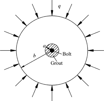
Fig. 5 Model for mechanical analysis of anchorage body
Equation (5) represents the bonding capacity between the anchoring agent and surrounding rock, the key to the design of anchoring support. When the tensile force imposed on the bolt exceeds this value, the bolt starts to fail.
Equation (5) shows that the bond strength between bolt anchoring agent and the soft and fractured rock interface has a negative correlation with bolt hole diameter, and it has a positive correlation with the interface dilation angle, surrounding rock cohesion, internal friction angle and surrounding rock stress. Among them, the rock stress can increase the carrying capacity of the bolt and anchorage. But it should not be neglected that when rock stress increases, deformation and failure of the surrounding rocks also occur, thus reducing the intensity of the rock. So, the rock stress is limited to increase the carrying capacity of the bolt and anchorage.
2.4 Engineering suggestions and measures
Based on the preceding theoretical analysis and the problems on site, the following principles and measures should be complied with in the design and the construction of bolt support for soft and fractured surrounding rocks with high stress:
(1) Under the action of high stress, surrounding rocks are loose and fractured. In particular, when surrounding rocks are soft with low self-support strength, the bonding capacity between the bolt anchoring agent and surrounding rocks is limited. This problem can be solved by using the anchoring agent with high sand content to improve the interface dilatancy, or using mechanical anchoring means to improve the bolt anchoring force.
(2) After solving the problem of the low bolt anchoring force, high pre-tightening force should be imposed on supporting components to continuously improve the active support effects and post-peak self- bearing capacity of surrounding rocks. Therefore, an effective self-bearing structure is formed on the anchored surrounding rocks and further deformation and failure of surrounding rocks are restricted.
(3) In the surrounding rocks, grouting reinforcement should be employed to continuously improve the integrity and strength of the surrounding rocks; it will help to avoid early slip of bolt support, increase the anchoring force, give full play to supporting potential of the components, and improve surrounding rock control effects.
3 High-strength bolt-grouting technology R&D and mechanical performance tests
The main problems in deep underground mining are serious deformation and failure of surrounding rocks, frequent failure of supporting components, and failure to give full play to supporting potential. Aiming at these problems, a new hollow grouting combined bolt with high strength is developed based on the concept of ��high- strength pre-stressed bolt-grouting��.
3.1 Structure and composition of new grouting combined bolt
Figure 6 shows the new hollow grouting combined bolt with high strength and its structural design.
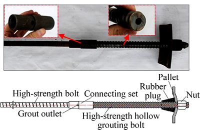
Fig. 6 New hollow grouting combined bolt with high strength and its structural design
This grouting combined bolt is composed of high- strength hollow grouting bolts, connecting sets, high- strength bolts, pallets and nuts. The hollow grouting bolt with high strength is full-threaded, it is 0.5�C1.5 m long with its body outer diameter of 25 mm and wall thickness of 6 mm, and it is formed after heat treatment and squeezing. The body of the high-strength bolt is 1.5�C3 m long, made of ��20 KMG500 high-strength left- lateral threaded steel without longitudinal reinforcement, and a thread of 100 mm is rolled at one end of the connecting set. The high-strength grouting bolt and the high-strength bolt are connected with the connecting set which is processed with a special high-strength treatment. The connecting set has the grout outlet in the middle and internal threads corresponding to the grouting bolt surface thread and high-strength bolt rolling thread, respectively, at both ends.
In field construction, the new combined bolt is installed with the following steps: 1) Connect the high-strength bolt and high-strength hollow grouting bolt with the connecting set; 2) Bore holes on the surrounding rocks and put the resin stick into the boreholes; 3) Place the high-strength hollow grouting combined bolt into the surrounding rock borehole, and install it with the bolt drill; 4) Tension the bolt and impose pre-tightening force after the resin stick solidifies; 5) Use this new high- strength grouting bolt to conduct grouting reinforcement on surrounding rocks.
3.2 Mechanical performance test on new grouting bolt
To further clarify the mechanical performance of the high-strength hollow grouting bolt body, the conventional MLX50-27/32Z*2000 hollow grouting screw bolt, and the new high-strength hollow grouting bolt are selected. Three tensioned specimens of 0.5 m long of each kind of bolts are cut to conduct mechanical performance tests, as shown in Fig. 7. Table 1 lists the test results of different grouting bolt specimens.
Figure 7 and Table 1 show that the strength of the conventional bolt body is weakened due to its own grout outlet with a low bearing capacity averaging only 56.7 kN. However, the new high-strength hollow grouting bolt with improved bolt body materials and machining process has an obviously increased bearing capacity averaging 264 kN. The increased bearing capacity is almost 5 times that of the conventional bolt and equal to that of ��22 KMG500 thread steel bolt. Moreover, this new grouting bolt has trapezoidal thread on its surface and is less likely to cause the nut loosening.
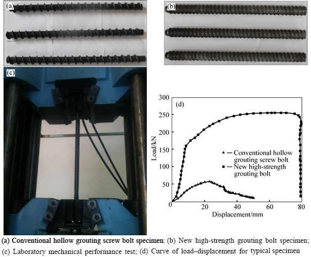
Fig. 7 Laboratory mechanical performance tests on different grouting bolts:
Table 1 Results of mechanical performance tests on different grouting bolts

According to analysis on the structural design, the installation method, and the contrast test results of mechanical performance of the new combined bolt, it has advantages in a high strength and pre-tightening force that can be imposed. Moreover, the anchoring section inside this bolt is anchored by resin sticks. After surrounding rock grouting is completed, the grout can effectively fill the free segment; thus, a full-length pre-tightening force anchoring is formed and the control effects of surrounding rocks are effectively enhanced.
4 Field application of high-strength bolt- grouting support technology
4.1 High-strength bolt-grouting supporting scheme
In locomotive maintenance chamber, a high- strength bolt-grouting support technology is designed with the new hollow grouting combined bolt, as shown in Fig. 8.
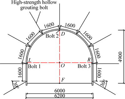
Fig. 8 Section design drawing in new high-strength bolt-grouting supporting scheme (Unit: mm)
The new hollow grouting combined bolt with high strength is 3 m long, and 1.5 m for each of the high-strength bolt and the high-strength hollow grouting bolt. The combined bolt is piled into the inter-row space on the bolt support section of the original supporting scheme with a 1600 mm��1600 mm inter-row spacing. The bottom corner bolt is installed 200 mm above the floor plane with a declination angle of 30��. The new high-strength grouting bolt is anchored by K25100 resin stick with the pre-tightening force of 60 kN. After the pre-tightening force is imposed on the bolt, cement is grouted with a pressure no more than 3 MPa. During field grouting, the following procedure is taken: grout the floor first, then side wall and finally the roof on the same section; grout on every other row on different sections. So, the grout leakage can be avoided on the field surrounding rocks, and in this way, the grout can be better diffused and filled in surrounding rock fractures to achieve better reinforcement effects.
4.2 Monitoring analysis on surrounding rock control effect
To monitor the surrounding rock control effect in the new high-strength bolt-anchoring supporting scheme, monitoring sections are set for the convergence deformation of surrounding rocks and the high-strength bolt force. Figures 9 and 10 show the corresponding monitoring results.
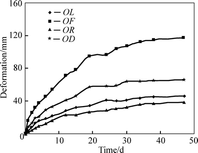
Fig. 9 Monitoring curves of roadway convergence deformation
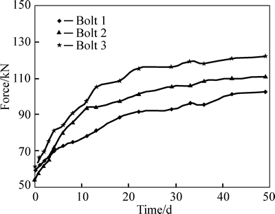
Fig. 10 Force monitoring curves of new high-strength grouting bolt
1) With the new high-strength bolt-anchoring supporting scheme, the deformation of surrounding rock tends to be stable and decreases remarkably after the grout solidifies. On the 50th day of excavation, the floor heave reaches the maximum of 117 mm; roof subsidence is 66 mm; side-to-side convergence is 85 mm; the deformation and failure of high-stress soft surrounding rocks are effectively controlled.
2) Due to high pre-tightening force imposed, the new high-strength grouting bolt is under generally large force with the maximum of 122 kN. Moreover, after surrounding rock grouting, the force on the bolt and anchor cable in the original supporting scheme also shows a continuous increase to some extent and no decrease.
The monitoring results show the superiority of the new high-strength bolt-grouting support technology which can effectively resolve the previously mentioned problems.
4.3 Control mechanism of new grouting combined bolt on surrounding rocks
4.3.1 High-strength support mechanism
The new high-strength hollow grouting combined bolt is used to grout and reinforce soft and fractured surrounding rocks. On one hand, the bolt itself has a high strength, can be imposed with large pre-tightening force and provides strong supporting loads for surrounding rock. On the other hand, the grout can effectively fill up the fractures in surrounding rocks and improve the integrity, completeness and self-bearing capacity of surrounding rocks. In addition, it can effectively improve the bond strength on the interface of the surrounding rock borehole with the high-strength grouting bolt, common bolt, anchor cable and anchoring agent. It will help to avoid too early failure of supporting components, give full play to supporting potential, and make supporting components and surrounding rocks form an effective bearing structure.
4.3.2 Full-length pre-stressed anchoring mechanism
The anchoring section inside this new high-strength hollow grouting bolt is anchored by resin sticks and imposed with high pre-tightening force. This ensures the effective diffusion of the pre-tightening force in surrounding rocks and enhances the active support effects of surrounding rocks [21]. Meanwhile, after the surrounding rock grouting is completed and the grout solidifies, the free segment of the bolt is effectively filled up by grout and a full-length pre-stressed anchorage is formed. Therefore, the pre-tightening force loss is effectively avoided and the bolt constraint is enhanced on surrounding rocks. So, separation, deformation and failure of surrounding rocks are effectively restricted in the free segment.
5 Conclusions
1) The locomotive maintenance chamber of 2# main roadway in Zhaolou Coal Mine is taken for example. The monitoring and measuring analysis is made on the convergence of the surrounding rock surface of the roadway, and on bolt and anchor cable force. It is shown that the deformation and failure of the soft surrounding rock with high stress are serious, and the bond strength on the interface between the anchoring agent and surrounding rocks is lower. They are the major factors causing frequent failure of bolting support which fails to give full play to supporting potential.
2) A calculation theory is established on the bond strength of the interface between the anchoring agent and surrounding rock. The analysis shows that the bond strength on interface between the bolt anchoring agent and the soft and fractured rock has a negative correlation with bolt hole diameter, and it has a positive correlation with interface dilation angle, surrounding rock cohesion, internal friction angle and surrounding rock stress. So, employing an anchoring agent with high sand content, mechanical anchoring means, or grouting reinforcement is an effective method to improve the anchoring force on soft surrounding rocks.
3) A new hollow grouting combined bolt with high strength is developed. Its bearing capacity is nearly 5-fold that of conventional hollow grouting screw bolt. The new bolt has advantages of a high strength and imposing pre-tightening force. With the high strength grouting bolt supporting, the deformation and failure of surrounding rock are stabilized, and the maximum bolt force is 122 kN. It is an effective solution to the deformation and failure of the soft and fractured surrounding rock with high stress, to the frequent failure occurrence on the supporting components and to the supporting potential not being fully played.
References
[1] KOV RI K. History of the sprayed concrete lining method��Part I: Milestones up to the 1960s [J]. Tunnelling and Underground Space Technology, 2003, 18(1): 57�C69.
[2] KOVRI K. History of the sprayed concrete lining method��Part II: Milestones up to the 1960s [J]. Tunnelling and Underground Space Technology, 2003, 18(1): 71�C83.
[3] HOU Chao-jiong, GOU Pan-feng. Mechanism study on strength enhancement for the rocks surrounding roadway supported by bolt [J]. Chinese Journal of Rock Mechanics and Engineering, 2000, 19(3): 342�C345. (in Chinese)
[4] INDRARATNA B. Effect of bolts on failure modes near tunnel openings in soft rock [J]. Geotechnique, 1993, 43(3): 433�C442.
[5] INDRARATNA B, KAISER P K. Analytical model for the design of grouted rock bolts [J]. International Journal for Numerical and Analytical Methods in Geomechanics, 1990, 14(4): 227�C251.
[6] LI C, STILLBORG B. Analytical models for rock bolts [J]. International Journal of Rock Mechanics and Mining Sciences, 1999, 36(8): 1013�C1029.
[7] BOBET A, EINSTEIN H H. Tunnel reinforcement with rockbolts [J]. Tunnelling and Underground Space Technology, 2011, 26(1): 100�C123.
[8] CAI Y, ESAKI T, JIANG Y. An analytical model to predict axial load in grouted rock bolt for soft rock tunneling [J]. Tunnelling and Underground Space Technology, 2004, 19(6): 607�C618.
[9] KANG H, WU Y, GAO F, LIN J, JIANG P. Fracture characteristics in rock bolts in underground coal mine roadways [J]. International Journal of Rock Mechanics and Mining Sciences, 2013, 62: 105�C112.
[10] LI C C. Field observations of rock bolts in high stress rock masses [J]. Rock Mechanics and Rock Engineering, 2010, 43(4): 491�C496.
[11] BLANCO M L, TIJANI M, HADJ-HASSEN F, NOIRET A. Assessment of the bolt-grout interface behaviour of fully grouted rockbolts from laboratory experiments under axial loads [J]. International Journal of Rock Mechanics and Mining Sciences, 2013, 63: 50�C61.
[12] KILIC A, YASAR E, ATIS C D. Effect of bar shape on the pull-out capacity of fully-grouted rockbolts [J]. Tunnelling and Underground Space Technology, 2003, 18(1): 1�C6.
[13] KILIC A, YASAR E, CELIK A G. Effect of grout properties on the pull-out load capacity of fully grouted rock bolt [J]. Tunnelling and Underground Space Technology, 2002, 17(4): 355�C362.
[14] REN F F, YANG Z J, CHEN J F, CHEN W W. An analytical analysis of the full-range behaviour of grouted rockbolts based on a tri-linear bond-slip model [J]. Construction and Building Materials, 2010, 24(3): 361�C370.
[15] CAO C, JAN N, REN T, NAJ A. A study of rock bolting failure modes [J]. International Journal of Mining Science and Technology, 2013, 23(1): 79�C88.
[16] YOU Chun-an, ZHAN Yu-bao, LIU Qiu-yuan, SUN Lin-lin, WANG Kai-bin. Shear lag-debonding model for anchorage section of prestressed anchor cable [J]. Chinese Journal of Rock Mechanics and Engineering, 2013, 32(4): 800�C806. (in Chinese)
[17] YOU Chun-an, ZHAN Yu-bao. Analysis of interfacial slip mechanics in anchorage section of anchor cable [J]. Chinese Journal of Rock Mechanics and Engineering, 2009, 28(10): 1976�C1985. (in Chinese)
[18] DAVIS R O, SELVADURAI A P. Plasticity and Geomechanics [M]. Cambridge University Press, 2002: 83-107.
[19] SADD M H. Elasticity: Theory, applications, and numerics [M]. Academic Press, 2014: 123-160.
[20] YIN J H, HONG C Y, ZHOU W H. Simplified analytical method for calculating the maximum shear stress of nail-soil interface [J]. International Journal of Geomechanics, 2011, 12(3): 309�C317.
[21] WANG Hong-tao, WANG Qi, WANG Fu-qi, LI Shu-cai, WANG De-chao, REN Yao-xi, GUO Nian-bo, ZHANG Shi-guo. Mechanical effect analysis of bolts in roadway under different anchoring lengths and its application [J]. Journal of China Coal Society, 2015, 40(3): 509-515.
(Edited by YANG Bing)
Foundation item: Projects(51304125, 51379114) supported by the National Natural Science Foundation of China; Project(BS2013NJ004) supported by Award Fund for Outstanding Young and Middle-Aged Scientist of Shangdong Province, China; Project(201301004) supported by the Innovation Fund for Postdoctor of Shandong Province, China
Received date: 2014-12-09; Accepted date: 2015-03-11
Corresponding author: WANG Qi, PhD; Tel: +86�C13583120068; E-mai: wangqi@sdu.edu.cn

