
Magnetoelectric voltage coefficients of magnetoelectric composites
WAN Yong-ping (����ƽ), ZHONG Zheng (�� ��)1, QIU Jin-hao(�ý���)2
1.School of Aerospace Engineering and Applied Mechanics, Tongji University, Shanghai 200092, China;
2. Institute of Fluid Science, Tohoku University, Sendai 980-8577, Japan
Received 10 April 2006; accepted 25 April 2006
Abstract: The magnetoelectric(ME) effect of the particulate magnetostrictive/piezoelectric composite was theoretically studied. The dependence of the ME voltage coefficients on the material properties of the magnetostrictive phase was discussed. The permittivity, permeability and the elastic modulus of the magnetostrictive phase generally have obvious influences on the ME voltage coefficients. The magnetostrictive phase with a large permittivity, large permeability or stiffer modulus will respectively contribute to the higher ME voltage coefficients. For a certain kind of piezoelectric matrix, the ME voltage coefficients can be improved to some extent by choosing those magnetostrictive materials with large permittivity, permeability or high elastic modulus.
Key words: magnetoelectric composite; magnetoelectric voltage coefficient; permeability; elastic modulus
1 Introduction
The magnetoelectric(ME) effect is an important effect of material, which might be extensively used in the signal generation, energy transformation, field sensing and microwave detection, etc [1-6]. The Terfenol-D-
based multiferroic composites, which are composed of the Terfenol-D phase and the piezoelectric matrix, exhibit very obvious ME effect and currently have been given more and more attention. Usually, the Terfenol-D powder is mixed with a piezoelectric matrix, i.e. PZT powder, to form a ME composite. Since the metallic Terfenol-D is electrically conductive, the magnetoelectric effect is low and even disappears when the composite incorporates a large volume fraction of magnetostrictive phase [3,4]. Therefore, The magnetostrictive and piezoelectric particulate composite is usually prepared with a low volume fraction of the magnetostrictive phase, especially for a conductive phase. Since the ME effect in this kind of multiferroic composite is actually originated from the magnetic-mechanical-electric interaction, in this paper, a theoretical model was developed based on the mechanical interaction of the two phase to study the ME voltage coefficients of the ME composites with a low volume fraction of magnetostrictive phase, where the magnetostrictive particles are sparsely scattered in the piezoelectric matrix and the interaction of particles can generally be neglected.
2 Model description
Similar to the model developed for the magnetostrictive composites[7], where different magnet-
ostrictive phases are mixed in the composite, this planar model was extended to study the ME effect of the magnetostrictive/piezoelectric particulate composites. Fig.1 shows the schematic diagram of an infinite piezoelectric plane with a circular magnetostrictive inclusion of radius, a, where the electric displacements, D��; the magnetic induction, B��, and the mechanical loading; ����, are exerted at infinity. A rectangular coordinate is attached to this plane, with the origin coinciding with the center of the circle. Without loss of generality, the polarization of the piezoelectric matrix (denoted by P) is aligned along the  axis. s, ��, g are the elastic compliance, dielectric impermeability, piezoelectric tensors of the piezoelectric matrix, respectively.
  is the saturated magnetostrictive coefficients along the magnetic field direction. ��I and
  are the magnetic permeability and the shear modulus of the inclusion, respectively. The bold type letters refer to tensors or vectors.
The general 3-dimensional piezoelectric equations have been well known. To study the electromechanical behavior, SOSA[8] used the complex variable method to treat the planar piezoelectricity. In terms of the plane strain conditions, the general piezoelectric equations can be reduced to the 2-dimensional case. According to SOSA[8] the plane strain piezoelectric problem can be reduced to finding three complex potentials, ��k(zk), k=1,2,3, where zk=x1+��kx2. The stresses, strain, displacements, the electric fields, the electric potential and the electric displacements in the piezoelectric material can all be analytically solved from the complex potentials. ��k and  (k=1,2,3) are the three pairs of complex roots of the characteristic equation in Ref.[8]. An over bar refers to the complex conjugate.

Fig.1. Infinite piezoelectric plane with circular magnetostric-tive inclusion
Usually, magnetostriction of material varies nonlinearly with the external magnetic field. The constitutive behavior of the magnetostrictive material is essentially nonlinear[9-11]. When the magnetic field is very strong, magnetization saturates and magnetostriction keeps a constant. A simple model to characterize the nonlinear behavior of magnetostriction is the standard square constitutive model of magnetostriction[9,10]. In this paper, the plane strain case of the standard square constitutive model of magnetostriction was also used as was done by WAN et al[7]. The magnetic field can be solved independently without considering magnetoelastic interaction. The distribution of magnetic field can also be obtained by means of the complex variable method. For a circular inclusion embedded in an infinite plane, the complex potentials of the magnetic induction for the inclusion and matrix, wI(z) and wM(z), which were already obtained by WAN er al[7], should be used in the formulation of the magnetostrictive elasticity problem. For a general piezoelectric media, there are boundary conditions of mechanical and electrical origin. The tractions, the displacements, the normal component of electric displacement and the electric potential are, respectively, continuous across the interface. The boundary conditions on the interface (along the circle) include the continuity conditions of both the mechanical and electrical variables.
n?��I=n?��I=n?��M, (1a)
uI=uM (1b)
n?DI=n?DM , (1c)
��I=��M (1d)
where the superscript I and M refer to the quantities inside and outside of the circular domain. n is the outward normal unit at the interface for the circular domain. u is displacement vector, �� the stress tensor, D the electric displacement vector, ��is the electric potential. These conditions in Eqn.(1) are universal along the interface of any dielectric continuum. From these boundary conditions, the complex potentials ��k(zk) (k=1,2,3) can be obtained. The various fields in the piezoelectric matrix can be determined in terms of the obtained complex potentials and remote conditions. To find the ME voltage coefficients, the electric potential is used to obtain an average electric field in the piezoelectric matrix and explicitly listed in Eqn.(2), in which��0 is the reference potential.

 (2)
(2)
where ��Re�� refers to the real part of the complex number. ��k is related to the physical plane zk in terms of the following conformal mapping functions:
 (k=1,2,3) (3)
where  . The coefficients are listed as follows:
 (4a)
(4a)
 (4b)
(4b)
 (4c)
(4c)

 (5)
(5)

 (6a)
(6a)

 (6b)
(6b)

 (6c)
(6c)

 (6d)
(6d)

 (6e)
(6e)
 (6f)
(6f)
 (7a)
(7a)
 (7b)
(7b)
 (7c)
(7c)
The value of k in Eqns.(7a)-(7c) ranges from 1 to 3.
 (8a)
(8a)
 (8b)
(8b)
 (8c)
(8c)
 (9a)
(9a)
 (9b)
(9b)

 (9c)
(9c)

 (9d)
(9d)

 (9e)
(9e)

 (9f)
(9f)
 (10)
(10)
 (11a)
(11a)
 (11b)
(11b)
 (11c)
(11c)
 (11d)
(11d)
 (11e)
(11e)
 (11f)
(11f)
where E and v are the elastic modulus and the Poisson��s ratio of the inclusion.  and
and  are the magnetostrictive coefficients of the inclusion along external magnetic field and the perpendicular direction, respectively [10]. ��0 and
  are, respectively, the permittivity of vacuum and the inclusion. The coefficients aij(i, j=1,2,3), bij(i, j=1,2,3), c����(��,��=1, 2, 3) in the Eqn.(11) can be referred to Ref.[8]. �� in the Eqn.(9) is also a coefficient, whose detailed expression was given in Ref.[7]. The coefficients fk, (k=1,2,3) in Eqn.(2), should be determined in terms of the remote mechanical and electric conditions. Each equation in Eqn.(9) can be further written with the remote conditions as
 (12a)
(12a)
 (12b)
(12b)
 (12c)
(12c)
 (12d)
(12d)
 (12e)
(12e)
 (12f)
(12f)
where  is the remote stress,
  is the remote electric displacement,
  is the remote rigid rotation, (��, ��=1,2).
3 ME voltage coefficients
To study the magnetoelectric voltage coefficients, only the magnetic loading was considered at infinity in the following discussion. For the ME composite with a low volume fraction of magnetostrictive particles, similar to the method in Refs. [7,12], the particle interaction is considered to be relatively weak and generally be neglected in this model. The ME voltage coefficients are defined to be the change of electric field induced by per unit external magnetic field variation [4].
 (13a)
(13a)
 (13b)
(13b)
where E�� is the electric field measured in the direction of polarization of the piezoelectric matrix, as indicated by P in Fig.1, while H�� is the magnetic field applied along the polarization direction, H�� is the magnetic field in the perpendicular direction. The measured electric field can be estimated to be the electric potential difference divided by their distance between two symmetric positions on the x2 (x2��a) axis, i.e.
 (14)
(14)
In order to graphically show and quantitatively discuss the ME voltage coefficients of ME composites, the following elastic, piezoelectric and dielectric parameters are used in the theoretical calculation,
a11=8.205��10-12 m2/N, a12=31.44��10-12 m2/N,
a22=7.495��10-12 m2/N, a33=19.3��10-12 m2/N,
b21=-16.62��10-3 m2/C, b22=23.96��10-3 m2/C,
b13=39.4��10-3 m2/C,c11=7.66��107 V2/N,
c22=9.82��107 V2/N
The Poisson��s ratio of the magnetostrictive material is v=0.3, and the magnetostrictive coefficients are
 , m12=-0.3 m11
The vacuum permeability and permittivity are, respectively,
��0=4��10-7 N/A2, ��0=8.853 8��10-12 N/V2
3.1 Dependence of ME voltage coefficients on permittivity of magnetostrictive phase
Since the rare earth (RE) giant magnetostrictive alloy is electrically conductive, the magnetoelectric composite with RE magnetostrictive alloy particles may lose the ME effect due to percolation when the volume fraction is very high. Therefore, this kind of ME composite is usually confined within a low volume fraction. For an ideal case where each magnetostrictive particle is completely separated by the piezoelectric matrix, we can investigate the dependence of the ME voltage coefficients, including ��31 and ��33, on the permittivity of the magnetostrictive phase.
Fig.2 shows the ME voltage coefficients plotted against the permittivity of the magnetostrictive phase. In the theoretical calculation, the elastic modulus of the magnetostrictive phase, E, is chosen to be the same as the elastic modulus of the piezoelectric material along the x1 direction, i.e. E/1/a11, where a11 is the compliance of the piezoelectric material. The relative magnetic permeability of magnetostrictive phase is��I=3. The bias magnetic field is chosen to be 100 A/m. Since the piezoelectric matrix occupying the area outside the circle is generally nonmagnetic, the relative magnetic permeability is considered to be the same as that of vacuum, i.e. ��M=1. It can be found, from Fig.2, that the ME coefficients, including ��31 and ��33, increase as the permittivity of the magnetostrictive phase becomes large. The ME voltage coefficients can be enhanced by improving the permittivity of the magetostrictive phase. This improvement measure, however, is limited since the ME voltage coefficients saturate when the permittivity of magnetostrictive phase becomes very large. The saturation value is actually the ME voltage coefficients when the magnetostrictive phase becomes a conductor. Therefore, for a perfect particulate magnetostrictive composite, the ME voltage coefficients can be enhanced, to some extent, by choosing a magnetostrictive material with a high permittivity ��r, i.e. the rare earth magnetostrictive alloy.

Fig.2 ME voltage coefficients vs permittivity of magnetostric-tive phase
3.2 Dependence of ME voltage coefficients on permeability of magnetostrictive phase
The dependence of the ME voltage coefficients on permeability of the magnetostrictive phase is graphically shown in Fig.3. In this calculation, the permeability ratio, r��, which is defined as r��=��M/��I, is adopted. Except the relative magnetic permeability and the permittivity of the magnetostrictive phase, all the other parameters are identical to those in Fig.2. It can be found from Fig.3 that the ME voltage coefficients, including ��31 and ��33, increase as the permeability of the magnetostrictive phase, ��I, improves. For a certain piezoelectric matrix, a magnetostrictive phase with a higher permeability will produce the larger ME voltage coefficients. This measure, however, is also limited due to the saturation trend of the ME voltage coefficients when the permeability becomes very large. Therefore, in a certain range, the ME voltage coefficients can be improved by means of selecting a magnetostrictive phase with a high permeability. The ferrite ceramic, for example, usually includes the simple ferrite ceramic and complex ferrite ceramic. The permeability of these two kinds of ferrite ceramic varies distinctly while the magnetostriction is almost the same. In terms of this analysis, the preferable ME voltage coefficients will be obtained for the ME composite with the complex ferrite inclusion than that with the simple ferrite inclusion.
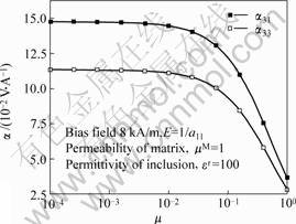
Fig.3 Curves of ME voltage coefficient vs magnetic permeab-ility ratio
3.3 Dependence of ME voltage coefficients on elastic modulus of magnetostrictive phase
The ME voltage coefficients are plotted against the elastic modulus of the magnetostrictive phase, E, as shown in Fig.4. It can be seen that the ME voltage coefficients, ��31 and ��33, increase as the elastic modulus becomes large. This implies that for a certain kind of piezoelectric matrix, a stiffer magnetostrictive phase produces larger ME voltage coefficients. Similarly, this measure for improving the ME voltage coefficients is also restricted in a certain range. In terms of Fig. 4, when the elastic modulus of the magnetostrictive phase is relatively small, i.e. E��a11��1, a small change in the elastic modulus leads to a distinct variation of the ME voltage coefficients. When the elastic modulus becomes very large compared to the piezoelectric matrix, the ME voltage coefficients saturate.

Fig.4 ME voltage coefficient plotted against elastic modulus of magnetostrictive phase,E
References
[1] RIVERA J P, SCHMID H, Linear and quadratic magnetoelectric(ME) effect in Ni-Cl boracite [J]. J Appl Phys, 1991, 70 (10): 6410-6412.
[2] EIJI K, SHUNSUKE T, AKIRA T, KILTI S, KA KY, SHIGEYUKI K. Low-temperature phase of yttrium iron garnet (YIG) and its first-order magnetoelectric effect [J]. J Appl Phys, 1988, 64 (10): 5659-5661.
[3] KIYOTAKE M, MANFRED W, Magnetoelectric coupling in terfenol-D/polyvinylidenedifluoride composites [J]. Appl Phys Let, 2002, 81(1): 100-101.
[4] NAN C W, CAI N, LIU L, ZHAI J, YE Y, LIN Y. Coupled magnetic�Celectric properties and critical behavior in multiferroic particulate composites [J]. J Appl Phys, 2003, 94(9): 5930-5936.
[5] BICHURIN M I, PETROV V M, SRINIVASAN G, Theory of low-frequency magnetoelectric coupling in magnetostrictive-piezoelectric bilayers [J]. Phys Rev B, 2003, 66: 054402.
[6] DONG Shu-xiang, LI Jie-fang, VIEHLAND D. Longitudinal and transverse magnetoelectric voltage coefficients of magnetostrictive/
piezoelectric laminate composite: theory [J]. IEEE Trans Ultra ferro Freq Contr, 2003, 50 (10): 1253-1261.
[7] WAN Y P, ZHONG Z, FANG D N. Permeability dependence of the effective magnetostriction of magnetostrictive composites [J]. J Appl
Phys, 2004, 95 (6): 3099-3110.
[8] SOSA H. Plane problems in piezoelectric media with defects [J]. Int J Solids Struc, 1991, 28 (4): 491-505.
[9] CARMAN G P, MITROVIC M. Nonlinear constitutive relations for magnetostrictive materials with applications to 1-D problems [J]. J Intell Mat Sys & Struc, 1996, 6: 673-683.
[10] WAN Y P, FANG D N, HWANG K C. Nonlinear constitutive relations for the magnetostrictive materials [J]. Int J Non linear Mech, 2003, 38: 1053-1065.
[11] ZHENG X J, LIU X E. A nonlinear constitutive model for Terfenol-D rods[J]. J Appl Phys, 2005, 97: 053901.
[12] HERBST J F, CAPEHART T W, PINKERTON F E. Estimating the effective magnetostriction of a composite: a simple model [J]. Appl Phys Let, 1997, 70: 3041-3043.
(Edited by LONG Huai-zhong)
Foundation items: Projects (10402028, 10432030) supported by the National Natural Science Foundation of China; Project (20050247003) supported by the Specialized Research Fund for the Doctoral Program of Higher Education of China
Corresponding author: ZHONG Zheng; Tel: +86-21-65982591; Fax: +86-21-65981138; E-mail: zhongk@mail.tongji.edu.cn

