恒电位电沉积银纳米枝晶晶体结构与形貌的关系
来源期刊:中国有色金属学报(英文版)2018年第9期
论文作者:Ljiljana AVRAMOVIC Evica R. IVANOVIC Vesna M. MAKSIMOVIC Miroslav M. PAVLOVIC Marina VUKOVIC Jasmina S. STEVANOVIC Nebojsa D. NIKOLIC
文章页码:1903 - 1912
关键词:电沉积;银;树枝晶;SEM;XRD
Key words:electrodeposition; silver; dendrites; SEM; XRD
摘 要:采用恒电位电解法用不同电解质、在不同过电位下获得银枝晶纳米结构,并用扫描电镜(SEM)技术和X射线衍射分析对所得粉末进行表征。采用硝酸盐电解质在极限扩散电流密度的平台范围内外,分别形成了银针状和蕨状枝晶。采用氨盐电解质时,在极限扩散电流密度的平台范围内外均形成了由近球形晶粒构成的银三维松树状枝晶。在半量子化水平上,银枝晶的形貌与其晶体结构相关。在极限扩散电流密度平台范围外的过电位条件下形成的松树状枝晶,其晶体取向从针状枝晶的强(111)面择优取向转变为球形晶粒的几乎随机取向,同时,所得粉末的比表面积显著增加。形成的银颗粒的平均晶粒尺寸在38~50 nm之间,证明了其纳米结构特征。
Abstract: Silver dendritic nanonstructures obtained by the potentiostatic electrolysis from different electrolytes at different overpotentials were characterized by the scanning electron microscopy (SEM) technique and X-ray diffraction analysis of the produced particles. The needle-like and fern-like dendrites were formed from the nitrate electrolyte at overpotentials inside and outside plateaus of the limiting diffusion current density, respectively. The three-dimensional pine-like dendrites constructed from approximately spherical grains were formed from the ammonium electrolyte at overpotentials both inside and outside plateaus of the limiting diffusion current density. The morphology of silver dendrites was correlated with their crystal structure at the semi quantiative level. The change of crystal orientation from the strong (111) preferred orientation for the needle-like dendrites to almost randomly orientied spherical grains in the pine-like dendrites obtained at the overpotential outside the plateau of the limiting diffusion current density was observed. This trend in change of crystal orientation and morphology of Ag nanostructures was accompanied by considerable increase of the specific surface area (SSA) of the produced powders. The average crystallite sizes were in the range of 38-50 nm, proving nanostructural character of the formed Ag particles.
Trans. Nonferrous Met. Soc. China 28(2018) 1903-1912
Ljiljana AVRAMOVIC1, Evica R. IVANOVIC2, Vesna M. MAKSIMOVIC3, Miroslav M. PAVLOVIC4, Marina VUKOVIC5, Jasmina S. STEVANOVIC4, Nebojsa D. NIKOLIC4
1. Mining and Metallurgy Institute, Zeleni bulevar 35, Bor, Serbia;
2. Faculty of Agriculture, University of Belgrade, Nemanjina 6, Belgrade-Zemun, Serbia;
3. Vinca Institute of Nuclear Sciences, University of Belgrade, Belgrade, Serbia;
4. Institute of Chemistry, Technology and Metallurgy, Department of Electrochemistry, University of Belgrade, Njegoseva 12, Belgrade, Serbia;
5. Institute for Multidisciplinary Research, University of Belgrade, Kneza Viseslava 1a, Belgrade, Serbia
Received 22 August 2017; accepted 28 March 2018
Abstract: Silver dendritic nanonstructures obtained by the potentiostatic electrolysis from different electrolytes at different overpotentials were characterized by the scanning electron microscopy (SEM) technique and X-ray diffraction analysis of the produced particles. The needle-like and fern-like dendrites were formed from the nitrate electrolyte at overpotentials inside and outside plateaus of the limiting diffusion current density, respectively. The three-dimensional pine-like dendrites constructed from approximately spherical grains were formed from the ammonium electrolyte at overpotentials both inside and outside plateaus of the limiting diffusion current density. The morphology of silver dendrites was correlated with their crystal structure at the semi quantiative level. The change of crystal orientation from the strong (111) preferred orientation for the needle-like dendrites to almost randomly orientied spherical grains in the pine-like dendrites obtained at the overpotential outside the plateau of the limiting diffusion current density was observed. This trend in change of crystal orientation and morphology of Ag nanostructures was accompanied by considerable increase of the specific surface area (SSA) of the produced powders. The average crystallite sizes were in the range of 38-50 nm, proving nanostructural character of the formed Ag particles.
Key words: electrodeposition; silver; dendrites; SEM; XRD
1 Introduction
Because of the unique electrical, chemical and optical characteristics, the silver nanostructures attract a great attention of both academic and technological communities [1]. The Ag nanostructures have wide applications in the electronics, optics, catalysts, gas sensing, chemical and biological sensing, in the surface-enhanced Raman scattering (SERS), etc [1-3]. Applications in the above mentioned technologies strongly depend on the shape and size of nanostructured forms, which are simultaneously dependent on the applied methods of synthesis. Various methods are used for their synthesis, and the common methods are seed-mediated growth [4], wet chemical [5,6], sonochemical [7], photochemical [7], electrochemical [1-3,7,8], microwave-assisted synthesis [2], template method [2,7], etc. The typical Ag nano- structures produced by these methods are polygons [9-12], wires or needles [1,2,13,14], and dendrites [2,7,8,9,15]. Numerous mechanisms have been proposed to explain the formation of Ag nanostructures, especially dendrites, but none of them give a complete insight into their formation. The usual mechanisms proposed for formation and growth of dendrites are diffusion-limited aggregation (DLA) [16,17], oriented attachment [18], nanoparticle- aggregated self-assembly crystallization [19], and anisotropic crystal growth [20].
Electrodeposition technique is a very suitable method to synthesize all types of metal structure at the micro and nano levels [21-28]. The advantages of this method of synthesis over the other methods are low equipment and product costs, one-step, environmentally friendly, formation of the high purity products, etc. [1]. The shape and size of electrodeposited forms can be easily regulated by a choice of parameters and regimes for electrolysis. The main parameters affecting the morphology of metal deposits are: composition and kind of electrolytes used for metal electrodeposition, type of working electrode, temperature of electrolysis, current density or potential applied during electrolysis, electrolysis time, the use of additives, etc. [2,3,21-23]. Simultaneously, the application of periodically changing regimes of electrolysis, such as the pulsating current (PC), reversing current (RC) and pulsating overpotential (PO), offers a great possibility for modeling the final surface morphology [21,29].
Formation of dendrites represents one of the largest challenges in the metal electrodeposition processes. The electrolytically produced dendrites belong to a group of irregular or disperse deposits that can be used either as an electrode of very high surface area, or in a form of powder particles, obtained by their removal from an electrode surface after the finished electrolysis process. In addition to the above mentioned parameters of electrolysis, the morphology of dendrites at micro and nano levels is strongly determined by the metal nature. Metals are usually classified depending on their exchange current density, melting point and overpotential for hydrogen discharge on normal, intermediate and inert metals [30]. Electrodeposition of metals from each of these groups produces dendrites of specific surface morphology [21,31-33].
It has been recently shown [34] that the application of ultrasound in formation of the Ag thin films using the electrolysis causes a modification of their crystal structure with the strong consequences on properties of the formed films, such as hardness and brightness. Following this fact, it can be assumed that a correlation also exists between the morphology of dendritic particles and their crystal structure with a possible effect on some of properties characterizing the behavior of metal powders as the collection of particles. Also, a certain correspondence between the Ag particles shapes and their crystal structures was reported previously [35]. Therefore, it is significant to further examine the correlation of morphology and the crystal structure of Ag particles, obtained by the potentiostatic regime of electrolysis. Herein, we reported the initial, semi- quantitative analysis of this correlation, which was associated with the specific surface area as one of the most important properties of metal powders.
2 Experimental
2.1 Electrochemical experiments
Electrodeposition of silver was carried out from the following electrolytes: 0.10 mol/L AgNO3 in 2.0 mol/L NaNO3 (nitrate electrolyte), and 0.10 mol/L AgNO3 in 0.50 mol/L (NH4)2SO4 with the addition of NH3 in excess to dissolve silver sulfate precipitate (ammonium electrolyte).
Silver was electrodeposited by a potentiostatic regime of electrolysis, in an open cell of a cylindrical shape at the room temperature. Doubly distilled water and analytical grade chemicals were used to prepare the electrolytes. Electrodeposition of silver was performed at the overpotentials of 90 and 150 mV from the nitrate electrolyte, and 625 and 925 mV from the ammonium electrolyte, using Pt as the working electrode. The reference and counter electrodes were made of pure silver. The working electrode had a cylindrical shape, a length of 4.0 cm, and a diameter of 0.7 mm (the overall surface area of 1.0048 cm2). The counter electrode (Ag) was in the form of foil with the overall surface area of 144 cm2, and was situated close to the cell wall. The working electrode was situated in the middle of the cell, while the tip of Ag reference electrode was positioned at a distance of about 2 mm from the surface of working electrode. For recording the polarization curves, Ag of the same shape and dimension as Pt was used for the working electrode.
2.2 Characterization of Ag particles produced by electrolysis
For morphological analysis, Ag was electro- deposited with electricity quantity of 0.50 (mA・h)/cm2. Morphologies of the potentiostatically produced particles were characterized using the technique of scanning electron microscopy (SEM) by the TESCAN Digital Microscopy-model VEGA3, Brno, Czech Republic.
The X-ray diffraction (XRD) analysis of Ag particles was carried out using the Rigaku Ultima IV diffractometer (Rigaku Co. Ltd., Tokyo, Japan), with Cu Kα radiation (1.54178  ) in 2θ range from 5° to 80°. For the XRD analysis, the Ag particles were removed from the electrode surface every 10 min, rinsed with distilled water and dried in a tube furnace under a controlled nitrogen atmosphere at 110-120 °C for 16 h. The preferred orientation of Ag particles was estimated by determining the texture coefficient, TC(hkl), and the relative texture coefficient, RTC(hkl) as follows [35,36].
The ratio of reflection intensity (hkl) to the sum of all intensities of the recorded reflections, R(hkl) is calculated according to Eq. (1):
 (1)
(1)
where I(hkl) is the reflection intensity (hkl), in cps, and  is the sum of all intensities of the recorded reflections, in cps, for the particles being considered.
The texture coefficient, TC(hkl), for every (hkl) reflection is defined by Eq. (2):
 (2)
(2)
where Rs(hkl) is defined in the same way as given by Eq. (1), but is related to the Ag standard (04―0783). This coefficient gives the accurate quantitative information about the absolute reflection intensity.
Finally, the relative texture coefficient, RTC(hkl) is defined by Eq. (3):
 (3)
(3)
The RTC(hkl) coefficient defines the reflection intensity (hkl) relative to the standard (included in the TC values).
The phase analysis was done using the Powder Cell software (Version 2.4). The average crystallite size (D) was calculated on the basis of the full-width at half-maximum intensity (FWHM) of the (111), (200), (220) and (311) reflection of FCC Ag applying the Scherrer formula, and the lattice strain of electro- deposited powders was estimated from the Williamson- Hall plots [37,38].
The specific surface area (SSA) of powders was determined using the MALVERN Instruments MASTERSIZER 2000 device. The values of SSA are obtained using the “Malvern Software” to control the apparatus operation and processing the obtained data.
3 Results and discussion
3.1 Polarization of Ag electrodeposition systems
The polarization curves for silver electrodeposition both from nitrate electrolyte (0.10 mol/L AgNO3 in 2.0 mol/L NaNO3) and ammonium electrolyte (0.10 mol/L AgNO3 in 0.50 mol/L (NH4)2SO4 with the addition of NH3 in excess to dissolve silver sulfate precipitate) are shown in Fig. 1. The dendritic growth commences at some overpotential inside the plateau of the limiting diffusion current density, and the plateaus are denoted by the vertical lines in Fig. 1 for both electrolytes. A clear difference in their shape and length can be seen from Fig. 1. The plateau of limiting diffusion current density characterizing the nitrate electrolyte is relatively short with a slope to the overpotential (η) axis (70-110 mV, Part I in Fig. 1). In the case of ammonium electrolyte, there is a wide and well defined plateau of the limiting diffusion current density with the current density independent of the overpotential (250-700 mV, Part I′ in Fig. 1). For both electrolytes, the current density increased strongly with the increase of over- potential after the end of plateau of the limiting diffusion current density (Parts II and II′ in Fig. 1). The overpotential denoting the end of plateau of the limiting diffusion current density, and separating the parts I, I′ and II, II′ at polarization curves, is denoted as the inflection point.
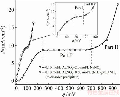
Fig. 1 Polarization curves for silver electrodeposition from nitrate and ammonium electrolytes
3.2 Morphology of electrochemically produced Ag dendrites
Figure 2 shows the morphologies of Ag particles obtained by the electrodeposition from nitrate electrolyte at overpotentials of 90 mV (Figs. 2(a)-(c)), and 150 mV (Figs. 2(d)-(f)). The needle-like dendrites like those shown in Figs. 2(a)-(c) were formed at the overpotential of 90 mV, which belong to the middle of the plateau of the limiting diffusion current density. As shown in Fig. 2(a), the needle-like dendrites grew oriented to the bulk solution during the electrolysis process. Apart from them, granules of various shapes, as the most dominant forms, were also formed during the electrodeposition process at the overpotential of 90 mV (Fig. 2(a)). Completely different forms of dendrites were formed by electrodeposition at the overpotential of 150 mV, in the zone of fast increase in the current density with increasing the overpotential after the inflection point (Figs. 2(d)-(f)). The 2D highly-branched fern-like silver dendrites with stalk and well defined branches were predominately formed by electrodeposition at this overpotential.
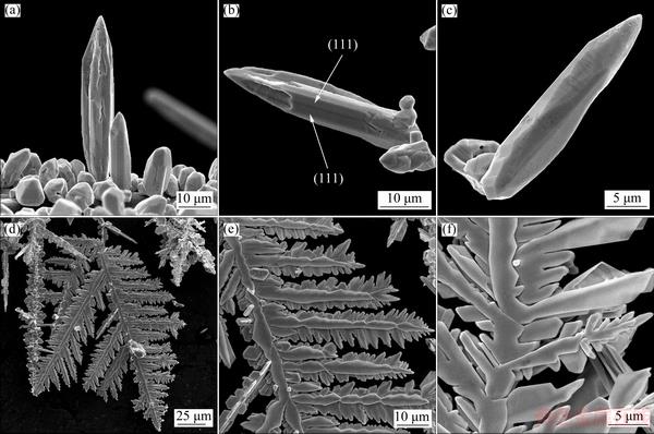
Fig. 2 Morphologies of Ag dendrites obtained by electrodeposition from nitrate electrolyte at overpotentials of 90 mV (a-c) and 150 mV (d-f)
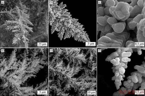
Fig. 3 Morphologies of Ag dendrites obtained by electrodeposition from ammonium electrolyte at overpotentials of 625 mV (a-c) and 925 mV (d-f)
Silver deposits, obtained by electrodeposition from the ammonium electrolyte at the overpotentials inside (h=625 mV) and outside (h=925 mV) plateau of the limiting diffusion current density, are shown in Fig. 3. At both overpotentials, the highly-branched 3D dendrites of the pine-like shape were formed from this electrolyte. It is necessary to note that the 3D pine-like dendrites, formed at 925 mV (Figs. 3(d) and (e)), were more branchy structure than those formed at 625 mV (Figs. 3(a) and (b)). This type of particles were constructed from the approximately spherical grains as the basic element (Figs. 3(c) and (f)). The size of these grains approached to the nano-size dimensions, with a tendency of their decrease with increasing the electrodeposition overpotential.
3.3 Crystal orientation and structure of Ag dendrites
3.3.1 Preferred orientation of formed Ag dendrites
The XRD patterns of silver particles electro- deposited from nitrate electrolyte at the overpotentials of 90 and 150 mV, together with the Ag standard (04―0783), are shown in Fig. 4. The peaks at 2q angles of 38.1°, 44.3°, 64.4° and 77.5° clearly indicate that silver crystallizes in a face centered cubic (FCC) lattice. At both overpotentials, the silver crystallites were dominantly oriented in the (111) plane due to a lower surface energy for this plane in relation to (200), (220) and (311) planes. Namely, the surface energies decrease in a row: y110>y100>y111, for the FCC crystal lattice [9,39]. A fast estimation of preferred orientation can be done using an analysis of the peak intensity ratios and their comparison with the corresponding standard [35]. Table 1 gives the ratio values of (111)/(200), (111)/(220) and (111)/(311) together with the Ag standard (04―0783) for silver particles electrodeposited at 90 and 150 mV. Considerably higher ratios of the peak intensity, observed for the Ag particles obtained at 90 mV in relation to the Ag standard, indicate a strong (111) preferred orientation. It is necessary to note that the contributions of crystallites, oriented in (200), (220) and (311) planes, were larger for particles obtained at 150 mV than those at 90 mV.
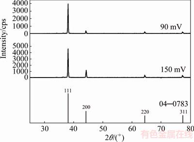
Fig. 4 XRD patterns of Ag particles electrodeposited from nitrate electrolyte at overpotentials of 90 and 150 mV, and Ag standard (04―0783)
A more precise estimation of preferred orientation is obtained by determining the texture coefficient, TC(hkl), and the relative texture coefficient, RTC(hkl) [35,36]. The values of these coefficients for the (111), (200), (220) and (311) planes are given in Table 2. Since four reflections were analyzed in this investigation, the RTC(hkl) values above 25% indicate the existence of preferred orientation of the formed crystals. It is very clear from Table 2 that there is a strong preferred orientation of Ag crystallites formed at 90 mV in the (111) plane. As far as the Ag crystals electrodeposited at 150 mV, aside from the dominant orientation of Ag crystallites in the (111) plane, a weak (200) preferred orientation can be indentified in these particles. The average crystallite size and lattice strain for the Ag particles, obtained at the overpotentials of 90 and 150 mV (Table 3), have pointed out a nanostructural character of the formed Ag particles. It can be seen from Table 3 that the average crystallite size decreased with an increase in the electrodeposition overpotential. On the contrary, the lattice strain increased with increasing the electrodeposition overpotential.
Table 1 Intensity ratios of diffraction peaks for dendritic particles obtained from nitrate electrolyte at 90 and 150 mV, ammonium electrolyte at 625 and 925 mV, and for Ag standard (04―0783) (Nitrate electrolyte-NIT; Ammonium electrolyte-AM)
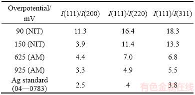
Table 2 Values of R, TC and RTC, obtained for Ag particles by electrodeposition from nitrate electrolyte at overpotentials of 90 and 150 mV
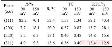
Table 3 Average crystallite size, lattice strain, and specific surface area of electrodeposited silver particles
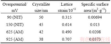
Figure 5 shows the XRD patterns of the pine-like particles, obtained from the ammonium electrolyte at the overpotentials of 625 and 925 mV, as well as the Ag standard (04―0783). The peaks at same angles as those obtained during the Ag electrocrystallization from nitrate electrolyte were observed for this type of electrolyte, confirming a face centered cubic (FCC) lattice of Ag. As seen from Fig. 5, the crystallites in the pine-like particles are dominantly oriented in the (111) plane, but with larger contributions in the (200), (220) and (311) planes regarding to the particles obtained from the nitrate electrolyte. The peak intensity ratios of (111)/(200), (111)/(220) and (111)/(311) for the particles obtained at 625 and 925 mV are also included in Table 1, from which it can be noticed that these ratios, except for the (111)/(200) ratio at 625 mV, were smaller than those observed for the particles produced in the nitrate electrolyte.
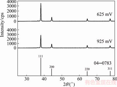
Fig. 5 XRD patterns of Ag particles electrodeposited from ammonium electrolyte at overpotentials of 625 and 925 mV, and Ag standard (04―0783)
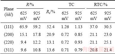
A more precise estimation of preferred orientation of the pine-like particles is also done by determining the TC(hkl), and the RTC(hkl) [35,36]. These coefficients for the (111), (200), (220) and (311) planes are given in Table 4. On the basis of calculated values, it can be concluded that the particles obtained at 625 mV show a (111) preferred orientation. On the other hand, the values for particles obtained at 925 mV were relatively close to 1 (TC coefficient), and about 25% (RTC coefficient), indicating a random orientation of Ag crystallites. The values of the average crystallite size, as well as the lattice strain of Ag powders electrodeposited from the ammonium electrolyte at the overpotentials of 625 and 925 mV, are also included in Table 3. It can be noted that changes of these values follow the same trend as in the powders obtained from the nitrate electrolyte. As expected, the values of the average crystallite size for particles obtained from the ammonium electrolyte were smaller than those obtained from nitrate electrolyte.
Table 4 Values of R, TC and RTC for Ag particles obtained by electrodeposition from ammonium electrolyte at overpotentials of 625 and 925 mV
3.3.2 Crystal structure of Ag dendrites
Various polygonal structures as well as the needle-like dendrites are obtained from the nitrate electrolyte at the overpotential of 90 mV (Figs. 2(a-c)). The needle-like dendrites are porous with a hollow void space at the top (Figs. 2(a) and (b)). These hollow structures are formed if the edges, instead of the corners, grow preferentially. Dendrite shown in Fig. 2(b) has one twinning boundary, formed by emergence of a twin plane (111) on a crystal surface (indicated by white arrows).
The fern-like dendrites are 2D because they grow and branch in one plane. Branching in one plane only is directly related to the occurrence of growth twins, and that at least one twinning boundary extends throughout a dendrite, and is parallel to the plane of dendrite [40]. Two or more twin planes insure the presence of at least one re-entrant edge resulting from an emergence of a twin plane on a crystal surface, which is a repeatable growth defect in faceted crystals. The twin grooves in nuclei are the lower energy sites for further nucleation and growth than on the faces [41]. The grooves are not only the sites of preferred nucleation, but also this type of nucleation preserves the stacking-order. The groove is reproduced in each new layer, and thus can act as a “self-perpetuating” step-source. The nucleation rate at twin plane re-entrant groove is much higher than that on the faceted surfaces or sharp corners, resulting in a fast growth rate along a crystallographic direction parallel to the twin plane. The twinning plane in a FCC crystal is (111), and the stalk and all branches are parallel to the <112> directions of growth (Figs. 2(d-f)) [42]. The stalk and branches of dendrites are formed by stacking of octahedrons mostly in an elongated form, and characteristic a “saw-tooth” arrangement of (111) planes are visible in Figs. 2(d-f). Lateral growth originating from the reentrant corners at the intersection of (111) planes cannot occur.
The same mechanism of growth as described for the fern-like dendrites can be applied to the pine-like ones, but in this case, dendrites also grow in thickness, by a layer growth mechanism. Some of the (111) facets on the main face that thicken and widen a dendrite, may arise passing throughout from the stalk. It is likely a dendrite branch in <111> direction, so that the main stalk and primary branches make an angle of nearly 90°. Thus, surface nucleation may be a mechanism for layer initiation on these final (111) faces. Hence, the three-dimensional dendrites branch in <112> and <111> directions, as seen in Fig. 3.
3.4 Discussion
It is very clear from Fig. 1 that the polarization characteristics of silver strongly depend on the type of electrolyte. When the nitrate electrolyte was used for Ag electrodeposition, Ag was situated into a group of normal metals, together with Pb, Sn, Cd and Zn [30]. These metals are characterized by the high exchange current density (J0  JL, where J0 is the exchange current density, and JL is the limiting diffusion current density), the low melting point and high overpotentials for hydrogen evolution. Electrodeposition of these metals belongs to the fast electrochemical processes, and they are characterized by a diffusion control of electrode- position process starting from the small overpotentials.
The processes of Ag electrodeposition from the ammonium electrolyte were characterized by the lower values both for the exchange current density and overpotential for hydrogen discharge than those from the nitrate electrolyte [30]. When the ammonium electrolyte was used, J0  JL is valid, and then, Ag is situated, together with Cu and Au, into a group of intermediate metals. The beginning of diffusion control is shifted to the higher overpotentials in relation to the normal metals, and the plateaus of the limiting diffusion current density were considerably wider for this type of electrolyte.
For both electrolytes, increasing overpotential led to a ramification of Ag dendrites (Figs. 2 and 3). Simultaneously, unlike the needle-like and the 2D fern-like dendrites formed from the nitrate electrolyte, the 3D pine-like dendrites were formed from the ammonium electrolyte. The strong difference in the shape of dendrites indicates the existence of different mechanisms of their formation. Irrespective of this, the dendritic growth is always initiated inside the plateau of the limiting diffusion current density. For the nitrate electrolyte (Ag behaves like a normal metal, J0 >> JL), the critical overpotential for initiation of dendritic growth, hi is given by [21]
 (4)
(4)
where nF is the number Faradays per mole of consumed ions, Rg is the gas constant, and T is temperature [21].
On the other hand, for the ammonium electrolyte (Ag behaves like an intermediate metal, J0JL ), the critical overpotential for the initiation of dendritic growth is given by
 (5)
(5)
where bc is the cathodic Tafel slope.
During electrolysis from both electrolytes, the outer limit of a diffusion layer of macroelectrode remains unchanged and the growth of dendrites at overpotentials, belonging to the plateaus of the limiting diffusion current density, occurs only inside the diffusion layer of macroelectrode. In case of the nitrate electrolyte, very long needle-like dendrites, oriented to bulk solution (Fig. 2(a)), leads to a noticeable increase of the real surface area of electrode, causing a formation of plateau of the limiting diffusion current density with a slope to the overpotential axis.
The inflection point at the polarization curves separating Parts I and I′ from Parts II and II′ corresponds to the critical overpotential for instantaneous dendritic growth, hc, and for the group of normal metals is given by [21]
 (6)
(6)
where d is the thickness of a diffusion layer, h is the height of protrusion from which the growth of dendrite starts, and  [43], where c is the concentration of the depositing ions.
For intermediate metals, the critical overpotential for the instantaneous dendritic growth is given by
 (7)
(7)
The overpotential hc, corresponds to an overpotential at which the diffusion control becomes complete. Formation of dendrites, as the only morphological forms, obtained at the overpotentials of 150 mV (Figs. 2(d-f)) and 925 mV (Figs. 3(d-f)) just confirms this fact.
The highly-branched 2D fern-like dendrites formed from the nitrate electrolyte are in excellent accordance with the classical Wranglen’s definition of dendrites. According to Ref. [44], a dendrite consists of a stalk and branches (primary, secondary, etc.), and resembles a tree. Dendrites, consisted only of a stalk and primary branches, are referred as the primary (P) dendrite. If the primary branches in turn develop the secondary branches, a dendrite is called as the secondary (S). It is clear that the highly-branched fern-like dendrites shown in Figs. 2(d-f) belong to the S type.
From an electrochemical point of view, a dendrite is defined as an electrode surface protrusion that grows under an activation control, while electrodeposition to the macroelectrode is predominantly under a diffusion control [21,45,46]. The electrochemical definition of a dendrite enables a closer definition of Parts II and II′ on polarization curves. After the inflection point, the electrodeposition system remains the diffusion controlled one, and the fast increase in the current density with increasing the overpotential is a consequence of strong increase of the real electrode surface, caused by instantaneous formation and growth of dendrites. Simultaneously, the tips of all elements constructing dendrites (stalk and branches) grow under the activation control causing a disruption of the outer limit of the diffusion layer of macroelectrode. As a result of all these simultaneous processes, a fast increase of the current density with an increase of overpotential occurred after the inflection point.
It is clear that the conditions of electrolysis, such as the overpotential of electrodeposition and the type of electrolyte, had not only a strong effect on morphology of the Ag nanostructures, but also on their crystal orientation. The change of preferred orientation from the strong (111) (the nitrate electrolyte: h=90 mV) to almost randomly distributed spherical grains in the pine-like dendrites (the ammonium electrolyte: h=925 mV) was observed with a change of the overpotential of electrodeposition and type of electrolyte. The explanation for this change can be found in the ramification of particles caused by increase of the overpotential of electrodeposition, and using the ammonium electrolyte instead of the nitrate electrolyte. Namely, for the both electrolytes, the increase in overpotential of the electrodeposition caused branching of dendrites, resulting in the increase of contributions of Ag crystallites oriented in the (200), (220) and (311) planes. The use of ammonium instead of nitrate electrolyte led to a change in shape of dendrites from the needle-like and 2D fern-like to the 3D pine-like ones, with a consequence that the 3D dendrites had more branchy structure than the 2D ones. The rate of electrochemical process (J0 value) was decreased using the ammonium electrolyte, and it is manifested in appearing the spherical morphology in the pine-like particles.
Then, a degree change of the preferred orientation of Ag dendrites from a strong (111) to almost random orientation can be explained as follows: as a consequence of different surface energies of crystal planes [9,39], the electrodeposition rates on them are different, and for the FCC crystal lattice, follow a trend: (110) > (110) > (111) [47]. Following this fact, the (111) plane is denoted as a slow-growing plane, while (200), (220) and (311) planes belong to a group of fast-growing planes [48]. In the growth process, the (111) plane as the slow-growing one survives, causing the dominant orientation of Ag crystallites in this plane, while the fast-growing (200), (220) and (311) planes disappear. The Ag crystallites oriented in the (111) planes originate from the growth centers present in the interior of crystal faces (“centre type”), while the Ag crystallites, oriented in the other planes, originate from the growth centers present on tips, edges and corners of the growing crystals (“edge” and “corner” type). Then, the increase of contributions of the Ag crystallites oriented in the (200), (220) and (311) planes, observed by increase in the overpotential and the use of the ammonium electrolyte can be ascribed to the branching of dendrites, i.e., a larger number of tips, edges and corners and hence, to the larger contribution of the crystal growth on them. It is necessary to note that this effect is especially expressed for the Ag particles obtained in the zone of instantaneous dendritic growth characterized by a fast increase in the current density with increasing the overpotential after the inflection point. As already mentioned, one of the main consequences of the rate decrease of electrochemical process is the appearing of spherical morphology which caused the approaching of the XRD pattern obtained from the ammonium electrolyte at 925 mV to the Ag standard for randomly distributed spherical grains.
The SSA values of the Ag powders presenting collection of the electrolytically produced dendrites are given in Table 3. The SSA produced powders increased with a change of electrolyte type from nitrate to ammonium ones, as well as with increase of the overpotential of electrodeposition. This can be ascribed to appearing the spherical morphology, achieved by the use of ammonium electrolyte and decrease of the grain sizes with increase the electrodeposition overpotential.
4 Conclusions
1) Depending on the kind of electrolyte and overpotential of electrodeposition, various forms of dendrites were obtained. The needle-like dendrites were formed from the nitrate electrolyte at the overpotential of 90 mV (the plateau of the limiting diffusion current density). The highly-branched 2D fern-like dendrites were formed from the same electrolyte at the overpotential of 150 mV (the zone outside the plateau of limiting diffusion current density). On the other hand, the 3D pine-like dendrites with spherical grains, as the basic construction element, were formed from the ammonium electrolyte at the overpotentials corresponding to the plateau of limiting diffusion current density (625 mV) and the zone outside this plateau (925 mV).
2) The needle-like dendrites showed a strong (111) preferred orientation. The highly-branched 2D fern-like dendrites showed an increased ratio of Ag crystallites oriented in the (200), (220) and (311) planes in relation to the needle-like dendrites. Finally, the 3D pine-like dendrites with almost randomly oriented crystallites were formed from the ammonium electrolyte at the overpotential outside the plateau of the limiting diffusion current density. The crystallite sizes in the formed Ag powders were in the range of 38-50 nm.
3) Morphologies of Ag dendritic nanostructures were successfully correlated with their crystal structure at the semi quantiative level that was verified by determination of the SSA of the obtained powders.
Acknowledgments
This work was supported by the Ministry of Education, Science and Technological Development of the Republic of Serbia under the research project: “Electrochemical synthesis and characterization of nanostructured functional materials for application in new technologies” (Project No. 172046).
References
[1] AMIRI M, NOUHI S, AZIZIAN-KALANDARAGH Y. Facile synthesis of silver nanostructures by using various deposition potential and time: A nonenzymatic sensor for hydrogen [J]. Materials Chemistry and Physics, 2015, 155: 129-135.
[2] FU Li, TAMANNA T, HU Wen-jing, YU A. Chemical preparation and applications of silver dendrites [J]. Chemical Papers, 2014, 68: 1283-1297.
[3] SIVASUBRAMANIAN R, SANGARANARAYANAN M V. A facile formation of silver dendrites on indium tin oxide surfaces using electrodeposition and amperometric sensing of hydrazine [J]. Sensors and Actuators B: Chemical, 2015, 213: 92-101.
[4] YI Zao, ZHANG Jian-bo, HE Hua, XU Xi-bin, LUO Bing-chi, LI Xi-bo, LI Kai, NIU Gao, TAN Xiu-lan, LUO Jiang-shan, TANG Yong-jian, WU Wei-dong, YI You-gen. Convenient synthesis of silver nanoplates with adjustable size through seed mediated growth approach [J]. Transactions of Nonferrous Metals Society of China, 2012, 22: 865-872.
[5] ZHAI Ai-xia, CAI Xiong-hui, JIANG Xiao-ye, FAN Guo-zhi. A novel and facile wet-chemical method for synthesis of silver microwires [J]. Transactions of Nonferrous Metals Society of China, 2012, 22: 943-948.
[6] ZHAI Ai-xia, CAI Xiong-hui, DU Bin. A novel wet-chemical method for preparation of silver flakes [J]. Transactions of Nonferrous Metals Society of China, 2014, 24: 1452-1457.
[7] CAI Wen-fang, PU Kai-bo, MA Qian, WANG Yun-hai. Insight into the fabrication and perspective of dendritic Ag nanostructures [J]. Journal of Experimental Nanoscience, 2017, 12: 319-337.
[8] POPOV K I, ZIVKOVIC P M, NIKOLIC N D. Formation of disperse silver deposits by the electrodeposition processes at high overpotentials [J]. International Journal of Electrochemical Science, 2012, 7: 686-696.
[9] SIVASUBRAMANIAN R, SANGARANARAYANAN M V. Electrodeposition of silver nanostructures: From polygons to dendrites [J]. Cryst Eng Comm, 2013, 15: 2052-2056.
[10] DIMITROV A T, HADZI-JORDANOV S, POPOV K I, PAVLOVIC M G, RADMILOVIC V. Electrodeposition of Ag from nitrate solutions: Part I. Effect of phosphate ions on morphology [J]. Journal of Applied Electrochemistry, 1998, 28: 791-796.
[11] RADMILOVIC V, POPOV K I, PAVLOVIC M G, DIMITROV A, HADZI-JORDANOV S. The mechanism of silver granular electrodeposits formation [J]. Journal of Solid StateElectrochemistry, 1998, 2: 162-169.
[12] YAN Yang, CHEN Ke-bin, LI Hao-ran, HONG Wei, HU Xiao-bin, XU Zhou. Capping effect of reducing agents and surfactants in synthesizing silver nanoplates [J]. Transactions of Nonferrous Metals Society of China, 2014, 24: 3732-3738.
[13] TAHERI M M, ABDUL KADIR M R, AHMAD SHAFIAI N K, SHOKUHFAR T, ASSADIAN M, SHIRDAR M R. Green synthesis of silver nanoneedles using shallot and apricot tree gum [J]. Transactions of Nonferrous Metals Society of China, 2015, 25: 3286-3290.
[14] TANG Shao-chun, VONGEHR S, WAN Neng, MENG Xiang-kang. Rapid synthesis of pentagonal silver nanowires with diameter-dependent tensile yield strength [J]. Materials Chemistry and Physics, 2013, 142: 17-26.
[15] JIANG Zhi-yuan, LIN Yuan, XIE Zhao-xiong. Structural investigations and growth mechanism of well-defined Ag dendrites prepared by conventional redox displacement [J]. Materials Chemistry and Physics, 2012, 134: 762-767.
[16] XIAO J P, XIE Y, TANG R, CHEN M, TIAN X B. Novel ultrasonically assisted templated synthesis of palladium and silver dendritic nanostructures [J]. Advanced Materials, 2001, 13: 1887-1891.
[17] HE Rong, QIAN Xue-feng, YIN Jie, ZHU Zi-kang. Formation of silver dendrites under microwave irradiation [J]. Chemical Physics Letters, 2003, 369: 454-458.
[18] FANG Ji-xiang, YOU Hong-jun, KONG Peng, YI Yan, SONG Xiao-ping, DING Bing-jun. Dendritic silver nanostructure growth and evolution in replacement reaction [J]. Crystal Growth & Design, 2007, 7: 864-867.
[19] ZHANG Gai-xia, SUN Shu-hui, BANIS M N, LIRu-ying, CAIMei, SUN Xue-liang.Morphology-controlled green synthesis of single crystalline silver dendrites, dendritic flowers, and rods, and their growth mechanism [J]. Crystal Growth & Design, 2011, 11: 2493-2499.
[20] DING Hui-ping, XIN Guo-qing, CHEN Kuang-cai, ZHANG Mao-li, LIU Qing-yun, HAO Jing-cheng, LIU Hong-guo. Silver dendritic nanostructures formed at the solid/liquid interface via electroless deposition [J]. Colloids and Surfaces A: Physicochemical and Engineering Aspects, 2010, 353: 166-171.
[21] POPOV K I, DJOKIC S S, NIKOLIC N D, JOVIC V D. Morphology of electrochemically and chemically deposited metals [M]. New York: Springer, 2016.
[22] NIKOLIC N D, IVANOVIC E R, BRANKOVIC G, LACNJEVAC U C, STEVANOVIC S I, STEVANOVIC J S, PAVLOVIC M G. Electrochemical and crystallographic aspects of lead granular growth [J]. Metallurgical and Materials Transactions B: Process Metallurgy and Materials Processing Science, 2015, 46: 1760-1774.
[23] NIKOLIC N D, STEVANOVIC S I, BRANKOVIC G. Nucleation and the early stages of growth of lead onto copper electrodes from the dilute electrolytes [J]. Transactions of Nonferrous Metals Society of China, 2016, 26: 3274-3282.
[24] ZAMANI M, AMADEH A, LARI BAGHAL S M. Effect of Co content on electrodeposition mechanism and mechanical properties of electrodeposited Ni-Co alloy [J]. Transactions of Nonferrous Metals Society of China, 2016, 26: 484-491.
[25] SEKAR R. Synergistic effect of additives on electrodeposition of copper from cyanide-free electrolytes and its structural and morphological characteristics [J]. Transactions of Nonferrous Metals Society of China, 2017, 27: 1665-1676.
[26] YUAN Liang, DING Zhi-ying, LIU Shi-jun, SHU Wei-fa, HE Ya-ning. Effects of additives on zinc electrodeposition from alkaline zincate solution [J]. Transactions of Nonferrous Metals Society of China, 2017, 27: 1656-1664.
[27] ZHANG Hui-zhong, LI Yang, ZUO Yu, ZHAO Xu-hui, TANG Yu-ming. Electrodeposition of multi-layer Pd-Ni coatings on 316L stainless steel and their corrosion resistance in hot sulfuric acid solution [J]. Transactions of Nonferrous Metals Society of China, 2017, 27(7): 1543-1550.
[28] SEAKR R. Microstructure and crystallographic characteristics of nanocrystalline copper prepared from acetate solutions by electrodeposition technique [J]. Transactions of Nonferrous Metals Society of China, 2017, 27(6): 1423-1430.
[29] ZHENG Zhou, TANG Shao-chun, VONGEHR S, MENG Xiang-kang. Square-wave electrochemical growth of lying three-dimensional silver dendrites with high surface-enhanced Raman scattering activities [J]. Materials Chemistry and Physics, 2011, 129: 594-598.
[30] WINAND R. Electrodeposition of metals and alloys―New results and perspectives [J]. Electrochimica Acta, 1994, 39: 1091-1105.
[31] NIKOLIC N D, VASTAG D D, MAKSIMOVIC V M, BRANKOVIC G. Morphological and crystallographic characteristics of lead powder obtained by electrodeposition from an environmentally friendly electrolyte [J]. Transactions of Nonferrous Metals Society of China, 2014, 24: 884-892.
[32] BENGOA L N, BRUNO S, LAZZARINO H A, SERE P R, EGLI W A. Study of dendritic growth of zinc crystals on the edges of steel sheet [J]. Journal of Applied Electrochemistry, 2014, 44: 1261-1269.
[33] OSTANINA T N, RUDOI V M, PATRUSHEV A V, DARINTSEVA A B, FARLENKOV A S. Modelling the dynamic growth of copper and zinc dendritic deposits under the galvanostatic electrolysis conditions[J]. Journal of Electroanalytical Chemistry, 2015, 750: 9-18.
[34] NEVERS A, HALLEZ L, TOUYERAS F, HIHN J Y. Effect of ultrasound on silver electrodeposition: Crystalline structure modification [J].Ultrasonics Sonochemistry, 2018, 40: 60-71.
[35] AVRAMOVIC L J, PAVLOVIC M M, MAKSIMOVIC V M, VUKOVIC M, STEVANOVIC J S, BUGARIN M, NIKOLIC N D. Comparative morphological and crystallographic analysis of electrochemically and chemically-produced silver powder particles [J]. Metals, 2017, 7: 160-14.
[36] BERUBE L P, ESPERANCE G L. A quantitative method of determining the degree of texture of zinc electrodeposits [J]. Journal of The Electrochemical Society, 1989, 136: 2314-2315.
[37] SURYANARAYANA C, NORTON M G. X-ray diffraction, a practical approach [M]. New York: Springer, 1998.
[38] KAROLUS M, LAGIEWKA E. Crystallite size and lattice strain in nanocrystalline Ni-Mo alloys studied by Rietveld refinement [J]. Journal of Alloys and Compounds, 2004, 367: 235-238.
[39] XIA Y, XIONG Y, LIM B, SKRABALAK S E. Shape-controlled synthesis of metal nanocrystals: Simple chemistry meets complex physics? [J]. Angewandte Chemie International Edition, 2009, 48: 60-103.
[40] SMIT J, OGBURN F, BECHTOLDT C J. Multiple twin structures in electrodeposited silver dendrites [J]. Journal of The Electrochemical Society, 1968, 115: 371-374.
[41] HAMILTON D R, SEIDENSTICKER R G. Propagation mechanism of germanium dendrites [J]. Journal of Applied Physics, 1960, 31: 1165-1168.
[42] IVANOVIC E R, NIKOLIC N D, RADMILOVIC V R. Randomly oriented twin domains in electrodeposited silver dendrites [J]. Journal of the Serbian Chemical Society, 2015, 80: 107-113.
[43] POPOV K I, NIKOLIC N D, General theory of disperse metal electrodeposits formation [M]//Electrochemical Production of Metal Powders, Series: Modern Aspects of Electrochemistry, Vol. 54. Springer, 2012: 1-62.
[44] WRANGLEN G. Dendrites and growth layers in the electrocrystallization of metals [J]. Electrochimica Acta, 1960, 2: 130-146.
[45] DIGGLE J W, DESPIC A R, BOCKRIS J O’ M. The mechanism of the dendritic electrocrystallization of zinc [J]. Journal of The Electrochemical Society, 1969, 116: 1503-1514.
[46] POPOV K I, KRSTAJIC N V, CEKEREVAC M I. The mechanism of formation of coarse and disperse electrodeposits [M]//Modern Aspects of Electrochemistry, Vol. 30. New York: Plenum Press, 1996. 261-312.
[47] BOCKRIS J O' M, REDDY A K N, GAMBOA-ALDECO M. Modern electrochemistry 2A, fundamentals of electrodics [M]. New York: Kluwer Academic / Plenum Publishers, 2000: 1333.
[48] NIKOLIC N D, MAKSIMOVIC V M, BRANKOVIC G. Morphological and crystallographic characteristics of electrodeposited lead from the concentrated electrolyte [J]. RSC Advances, 2013, 3: 7466-7471.
Ljiljana AVRAMOVIC1, Evica R. IVANOVIC2, Vesna M. MAKSIMOVIC3, Miroslav M. PAVLOVIC4, Marina VUKOVIC5, Jasmina S. STEVANOVIC4, Nebojsa D. NIKOLIC4
1. Mining and Metallurgy Institute, Zeleni bulevar 35, Bor, Serbia;
2. Faculty of Agriculture, University of Belgrade, Nemanjina 6, Belgrade-Zemun, Serbia;
3. Vinca Institute of Nuclear Sciences, University of Belgrade, Belgrade, Serbia;
4. Institute of Chemistry, Technology and Metallurgy, Department of Electrochemistry, University of Belgrade, Njegoseva 12, Belgrade, Serbia;
5. Institute for Multidisciplinary Research, University of Belgrade, Kneza Viseslava 1a, Belgrade, Serbia
摘 要:采用恒电位电解法用不同电解质、在不同过电位下获得银枝晶纳米结构,并用扫描电镜(SEM)技术和X射线衍射分析对所得粉末进行表征。采用硝酸盐电解质在极限扩散电流密度的平台范围内外,分别形成了银针状和蕨状枝晶。采用氨盐电解质时,在极限扩散电流密度的平台范围内外均形成了由近球形晶粒构成的银三维松树状枝晶。在半量子化水平上,银枝晶的形貌与其晶体结构相关。在极限扩散电流密度平台范围外的过电位条件下形成的松树状枝晶,其晶体取向从针状枝晶的强(111)面择优取向转变为球形晶粒的几乎随机取向,同时,所得粉末的比表面积显著增加。形成的银颗粒的平均晶粒尺寸在38~50 nm之间,证明了其纳米结构特征。
关键词:电沉积;银;树枝晶;SEM;XRD
(Edited by Xiang-qun LI)
Corresponding author: Nebojsa D. NIKOLIC; E-mail: nnikolic@tmf.bg.ac.rs
DOI: 10.1016/S1003-6326(18)64835-6

