
Effect of additive BaO on corrosion resistance of xCu/(10NiO-NiFe2O4)cermet inert anodes for aluminum electrolysis
HE Han-bing1, 2, XIAO Han-ning2, ZHOU Ke-chao3
1. School of Metallurgical Science and Engineering, Central South University, Changsha 410083, China;
2. School of Materials Science and Engineering, Hunan University, Changsha 410082, China;
3. State Key Laboratory of Powder Metallurgy, Central South University, Changsha 410083, China
Received 4 January 2010; accepted 12 April 2010
Abstract: xCu/(10NiO-NiFe2O4) cermet and 1BaO-xCu/(10NiO-NiFe2O4) cermet (x=5, 10, 17) inert anodes were prepared as potential inert anodes for aluminum electrolysis and their corrosion resistance to traditional electrolyte was studied with anodic current density of 1.0 A/cm2 in laboratory electrolysis. The substantial corrosion of metal Cu was observed, many pores appeared on the surface of anode and electrolytes infiltrated inside anodes during the electrolysis. The wear rates of 5Cu/(10NiO-NiFe2O4), 10Cu/(10NiO-NiFe2O4), 17Cu/(10NiO-NiFe2O4), 1BaO-5Cu/(10NiO-NiFe2O4), 1BaO-10Cu/(10NiO-NiFe2O4) and 1BaO-17Cu/ (10NiO-NiFe2O4) are 2.15, 6.50, 8.30, 4.88, 4.70 and 4.48 cm/a, respectively. The addition of BaO to 10Cu/(10NiO-NiFe2O4) cermet and 17Cu/(10NiO-NiFe2O4) cermet is advantageous because BaO can effectively promote densification and thus improve corrosion resistance. But the addition of BaO to 5Cu/(10NiO-NiFe2O4) cermet is unfavorable to corrosion resistance because additive BaO at the grain boundary of anode accelerates possibly the corrosion of cermet.
Key words: BaO; inert anode; aluminum electrolysis; cermet; corrosion resistance; wear rate
1 Introduction
The basic requirements for an inert anode include[1]: a low corrosion rate, a good electronic conductor, not contaminating the produced metal to any significant degree, thermal stability at electrolysis temperature as well as exhibiting adequate resistance to thermal shock, and economical feasibility. No material meets all these requirements[2-3] yet. A lot of research work has been carried out to find out a kind of appropriate material as inert anode[4-5]. NiFe2O4-based cermet, which has the desirable properties of metal and ceramic, and shows a good resistance against corrosion in the molten cryolite and a relatively high electrical conductivity, is one of the most promising materials as inert anode for aluminum electrolysis[6-9].
The corrosion resistance of NiFe2O4-based cermet as a potential inert anode material for aluminum electrolysis is dependent on its relative density. For conventional sintering, the densification is usually enhanced by increasing the sintering temperature, but the grain coarsening results in low mechanical properties and electric conductivity, especially corrosion resistance[10-11]. Activated sintering is an effective method to gain high relative density for cermets. The impact of lowering the sintering temperature on cermet composition and corrosion resistance was studied. LAI et al[12] observed that for cup-shaped inert anode consisting of cermet 17Ni/83(10NiO-NiFe2O4) with 100 mm in diameter, the contents of main impurities are Ni 0.1288% and Fe 1.0074%, and the corrosion rate under electrolysis conditions based on the content of impurity Ni in metal aluminum is approximately 8.51 cm/a. TIAN et al[13] revealed that there is preferential corrosion for metal Ni in NiO-NiFe2O4-based cermet anodes. By considering the corrosion resistance and electrical conductivity, the cermet containing 5%Ni (mass fraction) behaves the best among NiO-NiFe2O4-based cermet anodes, and should be further studied. XI[14] reported that V2O5 can improve the corrosion resistance and Ni2FeVO6 distributes along the grain boundary, which can control the chemical dissolution of ceramics anode and the reinforced grain boundary can control the grain- boundary corrosion rate. OLSEN and THONSTAD[15] found that the nickel level in the electrolyte did not reach steady state after electrolysis for 4 h and the total contaminant level of anode constituents in the deposited metal was as low as 0.116% (mass fraction). RAY et al[16-17] pointed out that the contaminant level of Cu-NiO-NiFe2O4 anode in the deposited metal was as low as 0.2 %Fe(mass fraction), 0.1 %Cu (mass fraction) and 0.034 %Ni (mass fraction).
Some metal oxides, such as BaO, may be the selective additives, which do not contaminate the aluminum produced. In order to give some available advices for the choice of anode constituent and good corrosion resistance, xCu/(10NiO-NiFe2O4) cermet and 1BaO-xCu/(10NiO-NiFe2O4) cermet (x=5, 10, 17) were prepared by cold isostatic pressing followed by pressureless sintering. The effect of additive BaO on the corrosion resistance of xCu/(10NiO-NiFe2O4) cermets was investigated .
2 Experimental
2.1 Preparation of sample
xCu/(10NiO-NiFe2O4) cermet and 1BaO-xCu/ (10NiO-NiFe2O4) cermet (x=5, 10, 17) were prepared by the conventional ceramic method with reagent grade raw materials of Fe2O3, NiO, Cu and BaO. Fe2O3 and NiO in the molar ratio of 1.35 were mixed and calcined in a muffle furnace at 1 200 ��C for 6 h in a static air atmosphere to form 10NiO-NiFe2O4 ceramic powder. The synthesized powders, Cu and BaO powder were ground in the medium containing dispersant and adhesive. The mass fraction of BaO was 1%. The dried mixture was compacted at a pressure of 200 MPa to get cylindrical blocks (d 20 mm��45 mm) and bars. Then, the cermets were sintered at 1 200 ��C for 4 h in nitrogen atmosphere at an efficaciously controlled oxygen partial pressure[18].
2.2 Characterization
Microstructure was analyzed with JSM-6360LV scanning electron microscope and EDX-GENESIS energy dispersive spectrometer. Bulk densities were tested according to the Archimedes�� method. Under the operating conditions of laboratory test, the electrolysis cell would not be thermally self-sustaining; it was necessary to provide extra heat by placing the cell in a vertical furnace. The furnace had a minimum cross-sectional diameter of 300 mm. The major components of the cell are shown in Fig.1.
The graphite crucible had an outside diameter of 105 mm and an inner diameter of 65 mm. The alumina
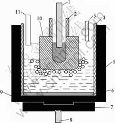
Fig.1 Sketch of electrolysis cell: 1��Anode rod; 2��Alumina sleeve; 3��Bath withdrawing tube; 4��Alumina liner; 5��Electrolyte; 6��Metal aluminum; 7��Graphite mechanical support; 8��Cathode rod; 9��Graphite crucible; 10��Inert anode; 11��Alumina feed tube
liner was 60 mm in inner diameter with a wall thickness of 2.5 mm. This liner extended from the lower crucible edge upward for 160 mm. It contained both the metal cathode pool and the cell electrolyte. The upper liner prevented oxygen generated at the anode from coming into contact with the graphite crucible or the furnace interior. It also defined the current path from the anode to the metal pool and not directly to the sidewall. Two stainless steel rods (diameter 8 mm) were used for electrical connection to the anode and cathode crucible.
The anode rod was insulated from the anode support bar by an insulating ring. In addition to supporting the anode assembly, this bar was used to raise and lower the anode to assure a proper distance between the anode and cathode during the electrolysis. The cathode rod was connected to the bottom of the graphite crucible and insulated from the furnace. The volume above the upper edge of the crucible and extending to the furnace wall was filled with insulating materials such as silica boards and light mass and high insulating fire brick.
2.3 Aluminum electrolysis
The electrolyte was prepared from reagent grade Na3AlF6, AlF3, CaF2 and A12O3. The compositions were 5% CaF2(mass fraction), 7.43% A12O3(mass fraction) and balance cryolite(n(NaF)/n(AlF3)=2.30). All compositions were dried at 120 ��C for 48 h to remove the water before using. The crucible contained a total of 300 g electrolyte. Metal aluminum (65 g) was added prior to electrolysis. The cell with inert anode was heated to the required temperature of 960 ��C and kept for 2 h before immersing the anode and electrifying for 20 min later. The immersion depth of anode was approximately 20 mm.
During electrolysis, the current was kept at 3 A; the current density of inert anode bottom was 1.0 A/cm2. The cell voltage and reference voltage between inert anode and aluminum electrode were measured. Bath samples were taken out just before the addition of alumina and further analyzed to determine the level of anode constituents in the melt.
After the test, the anode was raised out of the melt while maintaining polarization so as to prevent reduction of the anode material by dissolved metal. The anode above the electrolyte was cooled with the cell. Some of electrolyte samples taken out during electrolysis were dissolved by HClO4 solution, and analyzed with X-ray fluorescence spectroscope (XRF). The precision of analyses was approximately 10% (mass fraction) for the measured values below 100��10-6, 5% (mass fraction) for values between 100��10-6 and 1 000��10-6, and 3% (mass fraction) above 1��10-3. The anode was sectioned, polished and then analyzed with SEM/EDS.
The equation of corrosion rate of inert anode is
 (1)
(1)
where Wloss is the corrosion rate of inert anode (cm/a); mb is the total mass of electrolyte (g); wb is the mass fraction of impurity of electrolyte (10-6); ma is the total mass of aluminum after electrolysis (g); wa is mass fraction of impurity of aluminum after electrolysis (10-6); Sanode is total anode area immersed in electrolyte (cm2); ��anode is the relative density of anode (g/cm3); t is electrolysis time (h).
3 Results and discussion
3.1 Electrolyte test
YOUNG[19] observed that it took approximately 8 h for stoichiometric NiFe2O4 in cryolite melts to reach steady-state concentration, which is taken to be the solubility. LAI et al[20] showed that such a process would cost 4-6 h. Therefore, in present work all electrolysis experiments lasted for 10 h. As mentioned above, the electrolyte samples were taken out during electrolysis to study the dissolution process of the anode material. The samples were analyzed for the concentration of anode components in electrolyte during electrolysis, and a typical set of results are plotted in Fig.2.
From Fig.2(a), the steady-state of impurity Ba is approximately reached (The precision of analysis is 5%) and the mass fractions are 504��10-6, 592��10-6 and 680��10-6 for 1BaO-5Cu/(10NiO-NiFe2O4), 1BaO-10Cu/ (10NiO-NiFe2O4) and 1BeO-17Cu/(10NiO-NiFe2O4), respectively, when the electrolysis ends, indicating that Ba concentration increases with increasing Cu concentration of inert anode.
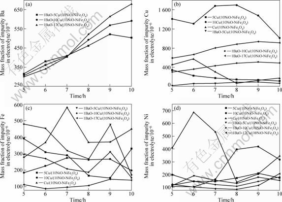
Fig.2 Elemental analyses of anode constituents in electrolyte versus time for cermet electrodes: (a) Ba in electrolyte versus time; (b) Cu in electrolyte versus time; (c) Fe in electrolyte versus time; (d) Ni in electrolyte versus time
During the electrolysis, the tendency of Fe, concentration changes in a similar manner to Ni, and Fe and Ni concentrations of cermet doped with 1%BaO (mass fraction) is lower than those of undoped cermet; after 10 h, the corresponding steady-state Fe mass fraction in 5Cu/(10NiO-NiFe2O4), 10Cu/(10NiO- NiFe2O4), 17Cu/ (10NiO-NiFe2O4), 1BaO-5Cu/(10NiO- NiFe2O4), 1BaO-10Cu/(10NiO-NiFe2O4) and 1BaO- 17Cu/(10NiO-NiFe2O4) are 329��10-6, 340��10-6, 449��10-6, 168��10-6, 154��10-6 and 139��10-6, respectively. And the corresponding steady-state Ni mass fractions are 176��10-6, 416��10-6, 346��10-6, 157��10-6, 182��10-6 and 207��10-6, respectively. However, the corresponding steady-state Cu mass fractions are 114��10-6, 1098��10-6, 170��10-6, 70��10-6, 491��10-6 and 912��10-6, respectively, which implies that Cu concentration of cermet doped with 1%BaO (mass fraction) is higher than that of undoped cermet.
3.2 Material performance
The cermet inert anodes after electrolysis are shown in Fig.3. It can be seen that there are not cracks on the anodic surface, implying that it is advantageous of addition of BaO to ceramic inert anode to improve the corrosion resistance.
SEM backscattered images of anodes post-testing are presented in Fig.4. From Fig.4, the metallic phase Cu
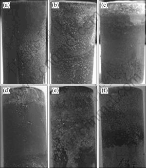
Fig.3 Photos of inert anodes after electrolysis: (a) 5Cu/ (10NiO-NiFe2O4); (b) 10Cu/(10NiO-NiFe2O4); (c) 17Cu/ (10NiO-NiFe2O4); (d) 1BaO-5Cu/(10NiO-NiFe2O4); (e) 1BaO- 10Cu/(10NiO-NiFe2O4); (f) 1BaO-17Cu/(10NiO-NiFe2O4)
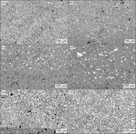
Fig.4 SEM backscattered images of cermet inert anodes at anode bottom: (a) 5Cu/(10NiO-NiFe2O4); (b) 1BaO-5Cu/(10NiO-NiFe2O4); (c) 10Cu/(10NiO-NiFe2O4); (d) 1BaO-10Cu/(10NiO-NiFe2O4); (e) 17Cu/(10NiO-NiFe2O4); (f) 1BaO-17Cu/(10NiO- NiFe2O4)
on the surface of anode used in bath was not preferentially corroded. According to LAI et al[12], the cermet inert anode was corroded at a stoichiometric ratio and peeled off layer by layer, but the thickness loss could not be seen from the picture. From Fig.4, only little Cu was lost.
From Fig.4, the lower of anode is metal corrosion layer and the upper is intrinsic layer. Moreover, the white part is metal Cu and the black part is ceramic 10NiO-NiFe2O4. Fig.4 shows that the loss of Cu used in 5Cu/(10NiO-NiFe2O4), 10Cu/(10NiO-NiFe2O4) and 17Cu/(10NiO-NiFe2O4) is serious and Cu disappears completely in the surface layer about 400, 300 and 300 ��m in thickness, respectively, However, Cu disappears completely in the surface layer of 1BaO-5Cu/ (10NiO-NiFe2O4), 1BaO-10Cu/(10NiO-NiFe2O4) and 1BaO-17Cu/(10NiO-NiFe2O4) about 50, 50 and 50 ��m in thickness, respectively. Therefore, from the SEM image (Fig.4), the corrosion resistance of cermet inert anode doped with 1%BaO(mass fraction) is better than that of undoped cermet.
3.3 Anode wear rate
From Table 1 and Table 2, we can see that the relative density of cermet doped with 1%BaO (mass fraction) is higher than that of undoped cermet. The total impurity mass (Fe, Ni and Cu) from 5Cu/(10NiO-NiFe2O4) cermet anode is the lowest in test, but total impurity mass from 10Cu/(10NiO-NiFe2O4) or 17Cu/(10NiO-NiFe2O4) cermet anode is higher than that from cermet doped with 1%BaO(mass fraction). Moreover, the wear rates of 5Cu/(10NiO-NiFe2O4), 10Cu/(10NiO-NiFe2O4), 17Cu/ (10NiO-NiFe2O4), 1BaO- 5Cu/(10NiO-NiFe2O4), 1BaO-10Cu/(10NiO-NiFe2O4) and 1BaO-17Cu/(10NiO-NiFe2O4) are 2.15, 6.50, 8.30, 4.88, 4.70 and 4.48 cm/a, respectively. The results mentioned above show that the effect of BaO on xCu/(10NiO-NiFe2O4) cermets may include two factors. On the one hand, BaO can effectively promote relative density of xCu/(10NiO- NiFe2O4) cermet and thus improves its corrosion resistance; on the other hand, BaO existed in the grain boundary maybe accelerate the corrosion of cermet (Fig.5). Thus, the corrosion resistance of 10Cu/(10NiO-NiFe2O4) cermet and 17Cu/10NiO-NiFe2O4 cermet doped BaO is advantageous because the former is a major factor of corrosion possibly. But the addition of BaO to 5Cu/(10NiO-NiFe2O4) cermet inert anode is adverse to corrosion resistance because the Cu content is a little and thus the latter is a major reason of corrosion possibly.
4 Conclusions
1) The tendency of Fe concentration changes in a similar manner to Ni, and impurity Fe and Ni concentrations of cermet doped with 1%BaO (mass fraction) are lower than those of undoped cermet. But impurity Cu concentration of cermet doped with 1%BaO(mass fraction) is higher than that of undoped cermet.
2) The corrosion resistance of cermet inert anode doped with 1%BaO(mass fraction) is better than that of undoped cermet.
3) The wear rates of 5Cu/(10NiO-NiFe2O4), 10Cu/ (10NiO-NiFe2O4), 17Cu/(10NiO-NiFe2O4), 1BaO-5Cu/ (10NiO-NiFe2O4), 1BaO-10Cu/(10NiO-NiFe2O4) and 1BaO-17Cu/(10NiO-NiFe2O4) are 2.15, 6.50, 8.30, 4.88, 4.70 and 4.48 cm/a, respectively.
4) The effect of BaO on xCu/(10NiO-NiFe2O4) cermets maybe include two factors. On the one hand, BaO can effectively promote relative density of xCu/(10NiO-NiFe2O4) cermet and thus improve its corrosion resistance; on the other hand, BaO in the grain boundary maybe accelerate the corrosion of cermet.
Table 1 Corrosion resistance of xCu/(10NiO-NiFe2O4) cermet
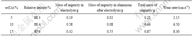
Table 2 Corrosion resistance of xCu/(10NiO-NiFe2O4) cermet doped with 1%BaO(mass fraction)
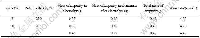
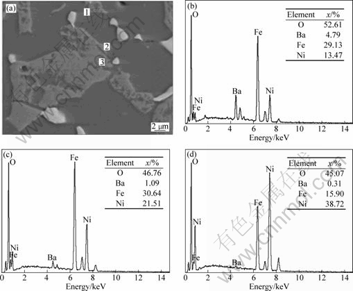
Fig.5 EDX analysis of 5Cu/(NiFe2O4-10NiO) cermet doped with 1.0%BaO: (a) EDX area of 5Cu/(NiFe2O4-10NiO) cermet doped with 1%BaO; (b) EDX analysis of zone 1; (c) EDX of zone 2; (d) EDX of zone 3
References
[1] OLSEN E, THONSTAD J. Nickel ferrite as inert anodes in aluminum electrolysis: Part ��. Material performance and long-term testing [J]. Journal of Applied Electrochemistry, 1999, 29(3): 301-311.
[2] THONSTAD J, FELLNER P, HAARBERG G M, HIVES J,KVANDE H, STERTEN A. Aluminum [M]. 3rd ed. Diisseldorf: Aluminium-Verlag, 2001: 328-338.
[3] YANG Jian-hong, LIU Ye-xiang, WANG Hua-hang. The behavior and improvement of SnO2-based inert anodes in aluminum electrolysis [C]//MILLER R E. Light Metals. Washington: TMS, 1993: 493-495.
[4] PETERSON R D, RICHARDS N E, TABEREAUX A T. Results of 100 hour electrolysis test of a cermet anode: Operational results and industry perspective [C]//MILLER R E. Light Metals. Washington: TMS, 1990: 385-393.
[5] HE Han-bing, LI Zhi-you, ZHOU Ke-chao. Progress of metal inert anodes in aluminum electrolysis [J]. Materials Review, 2008, 21(12): 69-72. (in Chinese)
[6] RAY S P. Inert anodes for Hall cells [C]//MILLER R E. Light Metals: Washington: TMS, 1986: 287-298.
[7] SADOWAY D R. Inert anodes for the Hall-Heroult cell: The ultimate materials challenge [J]. JOM, 2001,53(5): 34-35.
[8] HE Han-bing, ZHOU Ke-chao, LI Zhi-you. Progress in corrosion studies of NiFe2O4 based cermet inert anode [J]. Corrosion and Protection, 2008, 29(7): 359-364. (in Chinese)
[9] HE Han-bing, HUANG Bai-yun, LI Zhi-you, ZHOU Ke-chao. Effect of BaO doping on densification of 10NiO-NiFe2O4 composite ceramics [J]. The Chinese Journal of Nonferrous Metals, 2008, 18(5): 851-855. (in Chinese)
[10] HE Han-bing, ZHOU Ke-chao, LI Zhi-you, HUANG Bai-yun. Effect of BaO addition on the electric conductivity of xCu/10NiO-NiFe2O4 cermets[J]. Transactions of Nonferrous Metals Society of China, 2008, 18(5): 1134-1138.
[11] HE Han-bing, ZHOU Ke-chao, LI Zhi-you, HUANG Bai-yun. Effect of BaO addition on the densification and electric conductivity of 10NiO-NiFe2O4 composite ceramics [C]//Proceedings of 2007 China International Conference On Aluminum Metallurgy. Beijing: Metallurgical Industry Press, 2007: 84-89.
[12] LAI Yan-qing, TIAN Zhonh-liang, LI Jie, YE Shao-long; LI Xin-zheng, LIU Ye-xiang. Rusults from 100 h electrolysis testing of NiFe2O4 based cermets as inert anode in aluminum reduction [J]. Transactions of Nonferrous Metals Society of China, 2006, 16(8): 970-974.
[13] TIAN Zhong-liang, LAI Yan-qing, LI Jie, LIU Ye-xiang. Effect of Ni content on corrosion behavior of Ni/(10NiO-NiFe2O4) cermet inert anode[J]. Transactions of Nonferrous Metals Society of China, 2008, 18(1): 361-365.
[14] XI Jin-hui, XIE Ying-jie, YAO Guang-chun, LIU Yi-han. Effect of additive on corrosion resistance of NiFe2O4 ceramics as inert anodes [J]. Transactions of Nonferrous Metals Society of China, 2008, 18(1): 356-360.
[15] OLSEN E, THONSTAD J. Nickel ferrite as inert anodes in aluminum electrolysis: Part��. Material fabrication and preliminary testing [J]. Journal of Applied Electrochemistry, 1999, 29(3): 293-299.
[16] RAY S P, WEIRAUCH D A, LIU X. Inert anode containing oxides of nickel, iron and zinc useful for the electrolytic production of metals: US, 6423195 [P]. 2000-04-04.
[17] RAY S P, LIU X H, WEIRAUCH D A, DIMILIA R A, DYNYS J M, PHELPS F E, LACAMERA A F. Electrolytic production of high purity aluminium using ceramic inert anodes: US, 6416649 [P]. 2002-07-09.
[18] LAI Yan-qing, ZHANG Gang, LI Jie, LIU Ye-xiang. Effect of adding Cu-Ni on mechanical capacity and electrical conductivity of NiFe2O4-based cermets [J]. Journal of Central South University of Technology: Natural Science, 2004, 35(6): 880-884. (in Chinese)
[19] YOUNG D H. Solubilities of oxides for inert anodes in cryolite�Cbased melts [C]//MILLER R E. Light Metals. Washington: TMS, 1986: 299-307.
[20] LAI Yan-qing, TIAN Zhong-liang, QIN Qing-wei, ZHANG Gang, LI Jie. Solubility of composite oxide ceramics in the melt of Na3AlF6-Al2O3 [J]. Journal of Central South University: Natural Science, 2003, 34(3): 245-248. (in Chinese)
���Ӽ�BaO���������xCu/(10NiO-NiFe2O4)�����մɶ���������ʴ���ܵ�Ӱ��
�κ���1,2��Ф����2���ܿƳ�3
1. ���ϴ�ѧ ұ���ѧ�빤��ѧԺ����ɳ 410083��
2. ���ϴ�ѧ ���Ͽ�ѧ�빤��ѧԺ����ɳ 410082��
3. ���ϴ�ѧ ��ĩұ������ص�ʵ���ң���ɳ 410083
ժ Ҫ���Ʊ��������xCu/(10NiO-NiFe2O4) �� 1BaO-xCu/(10NiO-NiFe2O4) (x=5,10,17)�����մɶ����������ڴ�ͳ��������Ե����ܶ�1.0 A/cm2����ʵ���ҵ�ⸯʴʵ�顣�������������Cu����ʴ������������������������Ӷ������ڵ������е�����������ڲ����������մ�5Cu/(10NiO-NiFe2O4), 10Cu/(10NiO-NiFe2O4), 17Cu/(10NiO-NiFe2O4), 1BaO-5Cu/(10NiO-NiFe2O4), 1BaO-10Cu/(10NiO-NiFe2O4) ��1BaO-17Cu/(10NiO-NiFe2O4)�ĸ�ʴ���ʷֱ�Ϊ2.15��6.50��8.30��4.88��4.70��4.48 cm/a�����Ӽ�BaO��10Cu/(10NiO-NiFe2O4) �� 17Cu/(10NiO-NiFe2O4)�����մɵĿ���ʴ�����������ģ���Ϊ���Ӽ�BaO����Ч��������ܶȴӶ�����俹��ʴ���ܣ���BaO ��5Cu/(10NiO-NiFe2O4) �����մɵĿ���ʴ�����Dz����ģ���������Ϊ�ۼ��ھ�������Ӽ�BaO�����˽����մɵĸ�ʴ��
�ؼ��ʣ�BaO����������������⣻�����մɣ���ʴ���ܣ���ʴ����
(Edited by YANG Hua)
Foundation item: Project(2005CB623703) supported by the National Basic Research Program of China; Project(50721003) supported by the National Natural Science Foundation for Innovation Group of China; Project(2008AA030501) supported by the National High-tech Research and Development Program of China; Project(201012200021) supported by the Basic Scientific Research Program of Central South University, China
Corresponding author: HE Han-bing; Tel: 86-731-88876326; E-mail: hehanbinghhb@163.com
DOI: 10.1016/S1003-6326(11)60684-5

