ֱ���Ͳ�һ�γɾ������е��Ͳ۲����Ż�
��Դ�ڿ����й���ɫ����ѧ��(Ӣ�İ�)2018���7��
�������ߣ������� ���� ��Ϧ�� ����ΰ ����
����ҳ�룺1413 - 1423
�ؼ��ʣ��쾮��������Ͳۿױ��ƣ���ֵģ�⣻�Ͳ۲����Ż���������
Key words��shaft excavation; prime cutting blasting; numerical analysis; cutting parameter optimization; loading rate
ժ Ҫ����ֱ���Ͳ�һ�γɾ������У��Ͳ۲�����ѡ����Ͳ۵Ľ��Ӱ��ܴ�������ֵģ�ⷽ���о��Ͳ۲�������L�Ϳտ�ֱ��D���Ͳ۱����ƻ����Ĺ�ϵ��ͨ���û��Զ����ӳ�������һ���ƻ�״ָ̬�� �ã����������Ͳ۱���ѹ���ƻ����������ƻ�����ͬʱ�������1 �ͦ�2������ӳ�Ͳ۱���Ч����ָ�ꡣģ��������������һ������ֵ���L��ʹ����ָ���1�ͦ�2ͬʱ�ﵽ���ţ����Ͳ�Ч����ѡ�ͬʱ����L��������ֵʱ���տ�ֱ��DԽ���Ͳ�Ч��Խ�á����⣬�о�Ӧ���������ʺ͵�Ӧ�������Ͳ۱���Ч����Ӱ�죬���ָ����ʵ�ըҩ�������Ͳ۱��ƣ����������Ƶ���չ����ͳ����ܵ�Ӧ��������Ӧ����С�ͷ����Ӱ�졣
Abstract: The outcome of the cutting blasting in a one-step shaft excavation is heavily related to the cutting parameters used for parallel cutting method. In this study, the relationships between the cutting parameters (such as the hole spacing L and the empty hole diameter D) and damage zones were investigated by numerical simulation. A damage state index �� was introduced and used to characterize the crushing and crack damage zones through a user-defined subroutine. Two indices, i.e., ��1 and ��2 that can reflect the cutting performance, were also introduced. The simulation results indicate that an optimal value of L can be obtained so that the ��1 and ��2 can reach their optimal states for the best cutting performance. A larger D results in better cutting performance when the L value maintains its best. In addition, the influences of the loading rate and the in-situ stress on the cutting performance were investigated. It is found that an explosive with a high loading rate is suit for cutting blasting. The propagation direction and the length of the tensile cracks are affected by the direction and the magnitude of the maximum principal stress.
Trans. Nonferrous Met. Soc. China 28(2018) 1413-1423
Qi-yue LI1, Kai LIU1, Xi-bing LI1, Ze-wei WANG1, Lei WENG2
1. School of Resources and Safety Engineering, Central South University, Changsha 410083, China;
2. School of Civil Engineering, Wuhan University, Wuhan 430072, China
Received 27 March 2017; accepted 28 December 2017
Abstract: The outcome of the cutting blasting in a one-step shaft excavation is heavily related to the cutting parameters used for parallel cutting method. In this study, the relationships between the cutting parameters (such as the hole spacing L and the empty hole diameter D) and damage zones were investigated by numerical simulation. A damage state index �� was introduced and used to characterize the crushing and crack damage zones through a user-defined subroutine. Two indices, i.e., ��1 and ��2 that can reflect the cutting performance, were also introduced. The simulation results indicate that an optimal value of L can be obtained so that the ��1 and ��2 can reach their optimal states for the best cutting performance. A larger D results in better cutting performance when the L value maintains its best. In addition, the influences of the loading rate and the in-situ stress on the cutting performance were investigated. It is found that an explosive with a high loading rate is suit for cutting blasting. The propagation direction and the length of the tensile cracks are affected by the direction and the magnitude of the maximum principal stress.
Key words: shaft excavation; prime cutting blasting; numerical analysis; cutting parameter optimization; loading rate
1 Introduction
Shaft excavation has been widely applied in the development of underground mines and civil engineering [1-3]. SHATERPOUR-MAMAGHANI and BILGIN [4] described the difficulty and importance of shaft excavation in mining and civil engineering, and VENKATESH et al [5] described the application of shaft excavation in hydroelectric engineering. There are some traditional shaft excavation methods, such as ladder, cage raise and Alimak raising methods. However, these methods are gradually becoming obsolete due to low efficiency and poor working conditions. One-step shaft excavation technique based on parallel cutting has been developed in shaft excavation engineering due to its high efficiency, safety and low cost thanks to the rapid development of large-scale drilling equipment [6]. Whereas, there are still some difficult issues to be solved before it can be widely used, such as the determination of blasting parameters and the high degree of constriction or fixation for burden rock [7].
The formation of cut cavity is an important step in one-step shaft excavation. To ensure a satisfactory cavity, the blasting parameters including the cutting model, the empty hole diameter, the hole spacing and the dimensions of shaft section, should be properly determined. To date, few studies have been seen concerning on the blasting parameters quantification for one-step shaft excavation [8,9]. Fortunately, the relatively abundant studies of cutting blasting for tunnel excavation provide useful guidelines for the development of one-step shaft excavation [10-13]. ZARE and BRULAND [7] compared the design features between NTNU (Nonwegian University of Science and Technology) mode and Swedish mode. SOROUSH et al [14] noted that the diameter of the charging hole and the size of the tunnel section were the most critical blasting parameters in tunnel excavation. QIAO [15] built a mechanical model of the initiation delay time for parallel cut blasting by analyzing the two-phase fluid that was composed of broken rock pieces and explosion gases. Compared to tunnel excavation (with a depth of 3-4 m), the single excavation depth of a shaft (10-50 m) is much longer, which increases the difficulty in implementing this technology. Therefore, it is of great importance to study the optimization of cutting blasting parameters in one-step shaft excavation.
In the process of cutting blasting, it is crucial to determine the parameters of prime cutting blasting, where the empty holes are used as free surface and swelling space. Therefore, the size of the empty holes and the hole spacing between the prime cutting hole and the empty hole become the key factors [6]. In this study, to study the changes in the damage zone of prime cutting at different empty hole diameters and hole spacings, 25 numerical models of prime cutting blasting were built by ABAQUS. Two indices, i.e., the blasting energy utilization and the blasting energy agglutination, were defined to analyze the relationship between the prime cutting parameters and the blasting effect. The effects of loading rate and anisotropy of high situ stresses on prime cutting blasting performance and blasting induced damage zones were evaluated.
2 One-step shaft excavation technique
The model of parallel cutting with four empty holes was used to fragment rock because it can provide a large swelling space for subsequent cutting holes. The blasting process of prime cutting hole is shown in Fig. 1. Upon the initiation of the prime cutting hole, both a shockwave and high pressure are produced in the borehole, as shown in Fig. 1(a). Owing to the small burden between the empty holes and the prime cutting hole in the cutting pattern, the shockwave induces a strong reflected tensile wave at the interface of the borehole wall when it arrives at the wall of the empty holes. Once the dynamic tensile stress is higher than the rock tensile strength, spalling may be induced at periphery of the empty holes wall, as shown in Fig. 1(d). Radial cracks will form through the rock between the empty hole and prime cutting hole when the hole spacing is appropriate. The burden rock that is full of cracks is broken and then thrown out of the cavity by the static pressure effect of the detonation gas, as shown in Fig. 1(e). As the subsequent cutting hole blasting progresses in a prescribed order, the cavity is gradually expanded.
The above demonstration shows that the key factors for good cutting performance are the appropriate hole spacing, which creates a damaged zone through the burden between the empty holes and the prime cutting hole, meanwhile the diameter of the empty holes, which should not only meet the requirements of swelling space but also make full use of the reflected tensile wave energy.
3 Numerical simulation method
3.1 Dynamic material model of rock mass
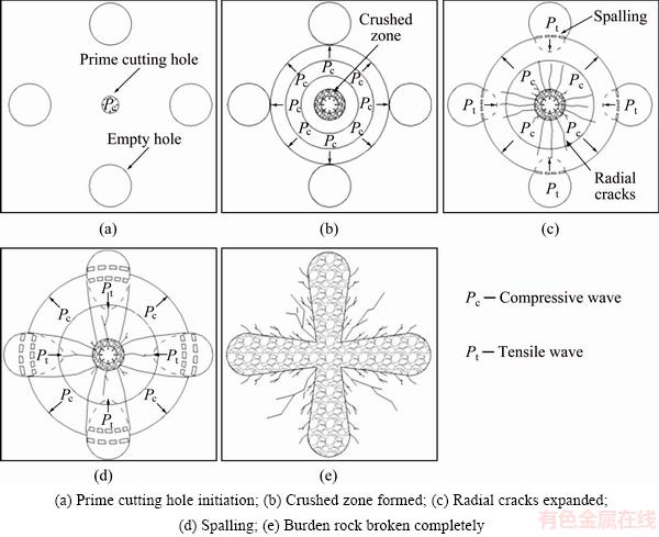
Fig. 1 Blasting process of prime cutting hole
Many brittle materials such as rock, ceramics and concrete have physical properties that are sensitive to strain rate. To obtain the relation of rock or rock-like material properties with different strain rates, researchers have conducted a large number of laboratory experiments [16,17]. LI et al [18] used a split Hopkinson pressure bar (SHPB) system to study the dynamic behaviors of red sandstone, marble and granite and found that the relationship between dynamic compressive strength and strain rate may be expressed using an exponential equation as follows:
 (1)
(1)
where ��cd is the dynamic compressive strength of the rock material,  is the loading strain rate, and C is a real constant for granite rock under a loading strain rate between 20 and 60 s-1. Here, C is found to be 64.9 [19].
The relationship between the dynamic compressive strength and the strain rate for brittle material, such as rock and concrete, is generally obtained in exponential or logarithmic form according to previous research [20-22]. In this paper, an exponential formula (see Eq. (2)) is used to represent the relation between the dynamic compressive strength and the strain rate:
 (2)
(2)
where ��cs is the static compressive strength of rock. Because the strain rates of rock adjacent to the charge hole wall can reach 103-105 s-1 [23], in this paper, the average strain rate of 1��104 s-1 [24] is used to calculate the ��cd in Eq. (2).
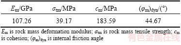
Table 1 summarizes the typical static mechanical properties of intact granite [25]. Because in this study Mohr-Coulomb failure criterion is used to do most dynamic analyses in ABAQUS, some rock mass properties such as cohesion and the internal friction angle must be calculated. Table 2 gives the dynamic mechanical properties of granite rock mass used in numerical analysis based on the Hoek-Brown criterion [26,27] when the geological strength index (GSI) is set to be 87. A GSI value of 87 represents the intact rock mass with few initial cracks and rock joints. This value is chosen considering the explosive energy used for breaking rock and serious explosive energy dissipation in the fragmentized rock mass. This selection does not specify any real conditions.
Table 1 Static mechanical properties of intact granite (Granite Bukit Timah (Singapare Zhao 1996))

Table 2 Dynamic mechanical properties of granite mass with GIS value of 87 (Granite Bukit Timah (Singapare Zhao 1996))
3.2 Blasting dynamic load
To simulate prime cutting hole blasting, an appropriate explosion pressure wave should be loaded on the borehole wall. There are three methods for approximating the explosive pressure profile [28]: 1) direct input of dynamic pressure as a function of time, 2) equation-of-state (EOS) and 3) pressure-decay functions. The Gaussian function and triangular load function are used to obtain the approximate measured dynamic-pulse load. These procedures, however, are not close to the physical characteristics of the dynamic load and thus carry no physical meaning.
The EOS describes material behavior under a very high-rate loading condition and the the equation is associated with different material quantities as a single function, regardless of the prior history of deformation. The parameters of the EOS for a detonation process may be considered incorrectly, leading to a lower accuracy of the EOS.
Although decay functions have been studied for decades, most blasting applications use pressure-decay functions that replicate the exact waveform. In this study, a general form of the pressure function of explosion pressure is expressed as follows [29]:
 (3)
(3)
where P is the pressure at time t, P0 is the peak pressure of the loading, and �� and �� are constants. To make the rising and decaying processes of the pressure wave more intuitive and convenient, two constants, i.e., t0= and
and  , are defined.
When the value of P reaches the peak point P0 at t=t0, Eq. (3) may be rewritten as
 (4)
(4)
The amplitude and duration of the pressure wave are determined by the explosive type and borehole size. In this paper, t0 is set to be 5 ��s, and P0 is set to be 1.6 GPa, based on the performance parameters of the ANFO explosive [24]. The pressure-time history used for numerical simulation is shown in Fig. 2.
3.3 Numerical model

Fig. 2 Pressure-time history acting on prime cutting hole wall
A 3D model, with an overall size of 12 m �� 4 m �� 4 m (depth �� length �� width), was established in the code. Firstly, a prime cutting hole, with a diameter of 70 mm and a depth of 10 m, was drilled in the center model, and four empty boreholes with an identical depth of 10 m were created around the center borehole, as shown in Fig. 3. To investigate the blasting effect of the prime cutting hole under different empty hole parameters in one-step shaft excavation, the diameter of an empty hole (D) was selected as 130, 160, 190, 220 and 250 mm, and the hole spacing (L) was selected as 260, 290, 320, 350 and 380 mm. A total of 25 experimental scenarios were designed using the orthogonal method and all of the scenarios satisfy the compensating space theory of Eq. (5) [30]:
 (5)
(5)
where L is the hole spacing between the prime hole and empty hole, d is the diameter of the prime cutting hole, D is the diameter of the empty hole and k is the rock swelling coefficient with the scope of [1.45, 1.90] [30].
In the rock blasting field of numerical models, boundary conditions generally cause the reflection of outward propagating waves to back into the model and do not allow the necessary energy radiation. To avoid this phenomenon, non-reflection boundaries are set on the outer side except the free surface.
In this study, hydrostatic stress conditions have been taken into account, considering a depth of 780 m for general mine work. The average unit weight is 25.50 kN/m3 for the rock mass, and the corresponding hydrostatic primary in-situ stress is calculated to be 20 MPa. Thus, the simulation process of prime cutting blasting involves two loading modes, i.e., static in situ stress and dynamic stress wave, which is a coupled static and dynamic loading problem. The problem can be solved through implicit-explicit analysis in ABAQUS. Firstly, the static in situ stress conditions are added and calculated in implicit module and then the non-reflection boundary conditions are set and dynamic loading process is computed based on the static results in explicit module.
3.4 Rock mass failure mode
KUTTER and FAIRHURST [31] proposed that there are crush zones, crack zones, and elastic zones from the blasting hole to a given distance when blasting in an infinite rock mass. In the first zone, the radial compressive stress generated from the shockwave exceeds the dynamic compressive strength of the surrounding rock, and the rock develops crush zones and, primarily, compression and shear failure (also called a shear failure zone). In the second zone, shockwaves expend a huge amount of energy in the process of crush zone formation and attenuate to a compression stress wave that cannot crush the rock mass. The compression wave pushes rock in an outward radial motion and produces radial tensile cracks due to hoop tensile stress to form a crack zone (also called a tensile failure zone).
To distinguish the damage zone in prime cutting blasting, a rock mass fracture degree index is defined by a field variable-vusdfld in the ABAQUS software called the damage state index :
:
 (6)
(6)
where ��max is the maximum principal stress in history, ��t is the dynamic tensile strength of the rock mass, ��eqp is the equivalent plastic strain, and �� is the rock damage state in the process of blasting, where 0�ܦ�<1 is the elastic zone, ��=1 is the tensile failure zone, and ��>1 is the shear failure zone.
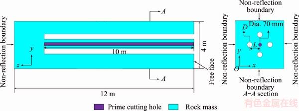
Fig. 3 Prime cutting blasting model geometry and boundary conditions
To evaluate the prime cutting hole blasting effect of different schemes, two indices, ��1 and ��2, are defined by
 ,
,  (7)
(7)
where S1 is the break area of prime cutting blasting under ideal conditions [6], S2 is the tensile failure zone area, R1 is the tensile failure zone radius of prime cutting blasting, and R2 is the tensile failure zone radius of single hole blasting. The parameters are illustrated in Fig. 4.
We can divide the energy consumption of a shock wave into four parts as follows:
Ew=Es+Et+Er+Ee (8)
where Ew is the total energy shock wave carried, Es is the energy spent in the creation of the shear failure zone, Et is the energy spent in the creation of the tensile failure zone, Er is the energy reflected from the empty holes wall, and Ee is the energy spent in the vibration of the elastic zone. The blasting energy is radially distributed in the shear failure zone, the tensile failure zone and the elastic zone when single hole blasting occurs in a rock mass, as shown in Fig. 4(a). The blasting energy will be reflected when the compressive stress wave propagates to the walls of empty holes and reflects as a tensile stress wave, as shown in Fig. 4(b). The value of reflective energy depends on the parameters of the empty hole.
Therefore, for ��1, the closer the value to 1 is, the more the blasting energy is used for cutting cavity, thus a better result is obtained with the increase of ��1. In contrast, for ��2, the closer the value to 0 is, the greater the concentration of blasting energy is, so the value of ��2 should be as small as possible for cutting.
4 Simulation results
4.1 Damaged zone formation processes on prime cutting blasting
Figure 5 shows the damaged zone formation processes of prime cutting blasting. It can be seen from Fig. 5(a) that the shock waves with sufficient compressive strength produce compression-shear damage around the prime cutting hole. The shear failure zone reaches the maximum when t=20 ��s, and then there are no dramatic changes for the zone after that time. As shown in Fig. 5(b), the shock wave expends a huge amount of energy in the shear failure zone and rapidly attenuates to stress waves producing tensile damage due to hoop tensile stress. As the stress waves propagate to the walls of empty holes, some of the compressive waves change to tensile waves due to reflection on the free surface, as shown in Figs. 5(c) and (d). The remaining stress waves continue to propagate through the rock mass between the empty holes. The tensile damage zone extends to the place where the hoop tensile stress is less than the dynamic tensile strength of the rock mass, as presented in Fig. 5(e). When stress wave fronts are encountered behind the empty holes, the hoop tensile stress increases in the superposition zone of stress waves, and when it exceeds the dynamic tensile strength of the rock mass, a tensile failure zone occurs behind the wall of empty holes, as shown in Fig. 5(f).
In order to avoid the influence of free surface, the section of shaft is chosen to be 2 m below the free surface. The numerical simulation results for the shear failure zone and tensile failure zone distribution under 25 different schemes are shown in Fig. 6. It can be seen that the size of the shear failure zone is independent of the parameters D and L. The outward expansion of the tensile failure zone decreases with a decrease in L, whereas the size of the tensile failure zone behind the empty holes decreases with an increase in D. The reason for this phenomenon is that with an increase in the diameter of empty holes, the reflection of stress waves is increased, leading to a decrease in the hoop tensile stress in the superposition zone of stress waves.
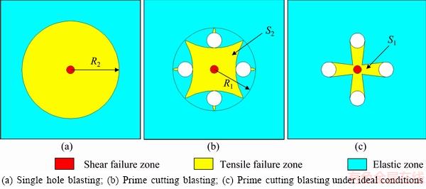
Fig. 4 Key parameters for representation of damaged zone
Fig. 5 Damaged zone formation processes of prime cutting blasting
Fig. 6 Simulation results of 25 schemes
4.2 Effect of hole spacing on prime cutting blasting
According to Eq. (7), the 25 scheme values of ��1 and ��2 can be determined. Then, the curves of hole spacing L versus ��1 and ��2 can be obtained by using different empty hole diameters, as seen in Fig. 7. It can be seen from Fig. 7 that the indices ��1 and ��2 reach their optimal values at L=350 mm. This is because when L is too small, the explosion pressure wave spreads out after passing through the prime cutting zone, leading to low energy utilization and concentration. Moreover, the rock between empty holes and the prime cutting hole may be excessively broken, and ��regenerated rock�� [6] may even be formed due to the small value of L. When L is too large, the prime cutting zone increases, and the areas of S1 and S2 increase respectively, with less in S1 and more in S2, which also induces low energy utilization and concentration. Rock may be incompletely broken, which is consistent with the results of LI et al [6]. The optimal value of the hole spacing L can be determined when ��1 and ��2 reach their optimal values based on numerical analysis. The optimal value of L is 350 mm for the 25 schemes in this study.
4.3 Effect of empty hole diameter on prime cutting blasting
Similarly, the indices ��1 and ��2 for different empty hole diameters D and hole spacing L can be obtained, as seen in Fig. 8. Combining the results of Fig. 6 and Fig. 8, the prime cutting blasting performance from the effect of empty hole diameter can be divided into three types, i.e., A (L=260 mm), B (L=290, 320 mm), and C (L=350, 380 mm) according to the shape of the tensile failure zone. Type A is called the diffusion type and is characterized by tensile cracks extending beyond the prime cutting zone. ��1 is independent of empty hole diameter D, whereas ��2 increases with an increasing D. Type C is called the cohesion type, where the tensile failure distributes in the prime cutting zone and no tensile cracks extend beyond the prime cutting zone. ��1 increases with an increasing D, whereas ��2 decreases with an increasing D. Type B is a transitional type between types A and C, where only a few cracks extend outward, and both ��1 and ��2 increase with an increasing D. This is probably influenced by the hole spacing: the hole spacing values of types A and B have not reached the optimal values, and most of the blasting energy diffuses from the prime cutting zone. However, the hole spacing of type C is optimal in the sense that ��1 and ��2 are in the optimal development direction with an increasing D. In this study, both ��1 and ��2 are optimal when D=250 mm.
Fig. 7 Relationships between ��1 (a), ��2 (b) and hole spacing L at different D values
Fig. 8 Relationships between ��1 (a), ��2 (b) and empty hole diameter D at different L values
An optimal value exists for the hole spacing L based on the theory of compensating space premise. When L is less than the optimal value, ��regenerated rock�� may be formed in the cavity, the volume of the formed cavity is too small to provide adequate swelling space for subsequent hole blasting, and a large size of tensile damage zone is formed beyond the prime cutting zone that is disadvantage for subsequent hole blasting. Because of drilling deviation, drilling will be more difficult. When L is larger than the optimal value, the constriction of rock mass is increased, and an effective cavity cannot be formed. The effects of the empty hole diameter D on prime cutting blasting performance can be divided into three types by the action of hole spacing, and ��1 and ��2 are in the optimal direction of development with increasing D when the hole spacing reaches the optimal value. Therefore, to obtain the ideal effect of cutting blasting in one-step shaft excavation, a larger diameter of the empty hole should be chosen to create a free surface and swelling space, and the optimal value of hole spacing can then be determined.
5 Discussion
5.1 Blasting performance under varying loading rate conditions
The mechanical properties of rock materials are affected by the loading rate. Previous studies showed that a higher loading rate tends to produce a larger shear failure zone followed by larger numbers of short fractures, whereas a lower loading rate results in a smaller shear failure zone with fewer and longer radial fractures [10,24]. To verify the loading rate effect on the dynamic damage process in cutting blasting, different explosion pressure waves are used in the analyses. The model size is kept consistent with the above, and cutting parameters are chosen at the optimal values of D=250 mm and L=350 mm. The peak pressure P0 is kept at a constant of 1.6 GPa, the rising time t0 is varied from 5, 10, 50 to 100 ��s. Figure 9 shows the pressure-time histories used for the numerical simulation.
The numerical results are shown in Fig. 10. When the loading rate of the explosion pressure wave is high (320 MPa/��s), most of the energy is spent in creating the prime cutting zone, although there are a few cracks outside the prime cutting zone. When the loading rate decreases to a lower level (160 MPa/��s), many short radial cracks appear behind the empty holes, and a part of the energy is spent outside the prime cutting zone. When the loading rate further decreases to 32 and 16 MPa/��s, there are many longer radial cracks following the empty holes, and more energy is spent in the area behind empty holes. From these results, it can be seen that to improve the efficiency of a mining blasting operation, which is indicated by long radial cracks, the loading rate should be kept as low as possible. However, the loading rate should be as high as possible for the cutting blasting of tunneling and shaft excavation, which requires that the energy be spent in the prime cutting zone to avoid forming a damage zone outside the prime cutting zone. It is well understood that cutting blasting requires more unit explosive consumption than mining blasting does.
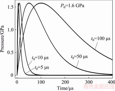
Fig. 9 Different pressure-time histories used for numerical simulation

Fig. 10 Simulation results of prime cutting blasting under different loading rates
5.2 Blasting performance under varying in-situ stress conditions
In deep underground mining, high in-situ stresses are usually present [32,33], which can affect the blasting operations. High in-situ stresses may have two effects in blasting operations [24]. The first effect is that the cracks that are induced by in-situ stress may be extended or suppressed by the blasting-induced stress field. The second effect is an induced stress concentration around the holes because of the in-situ stress leading to an asymmetrical fracture pattern under the action of different values of two principal stresses in the plane normal to the hole axis. To achieve a better cutting effect, it is important to study the crack propagation law of cutting blasting under earth stress. Because the hole axis of shaft excavation is vertical, the vertical stress is kept constant, and different anisotropic horizontal stresses are considered, the same model geometry and optimal cutting parameters (R=250 mm, L=350 mm, t0=5 ��s, P0=1.6 GPa) from previous work are used in this study. In the present numerical simulation, the numerical model is pre-loaded with different horizontal stresses and a fixed vertical stress. The assigned stress values for principal in-situ stresses are given in Table 3.
Table 3 Assigned stress values for principal in-situ stresses
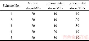
The simulated fracture patterns of cutting blasting model with different anisotropic in-situ stress fields are shown in Fig. 11, which clearly demonstrates that two effects occur in cutting blasting under high anisotropic in-situ stresses. The second effect can even eliminate the influence of the first effect. Figure 11(a) shows that tensile failures are radial when the horizontal stresses are equal, whereas the tensile failures are aligned in the direction of major horizontal principal stress axis; the larger the difference between two horizontal principal stresses is, the more obvious the phenomenon is. This is because the tensile stress perpendicular to the maximum horizontal principal stress axis is suppressed and the cracks tend to extend parallel to the maximum horizontal principal stress. However, it has been found that shear failure zones are not affected by anisotropic in-situ stresses. To increase the size of the cavity, the hole spacing L could be increased in the direction of the maximum horizontal principal stress.
6 Conclusions
1) There is an optimal value of hole spacing L between the prime hole and empty holes. When the L is less than the optimal value, the rock between empty holes and the prime cutting hole are broken excessively and form ��regenerated rock��. When L is greater than the optimal value, the rock will be broken incompletely.
2) The effect of prime cutting will be better with an increase in the empty hole diameter D when the value of L is optimal. The effect of prime cutting is less with an increase in D when L does not reach the optimal value.
3) Cutting blasting is suitable for using explosives with a high loading rate. For a high loading rate, there are few tensile cracks outside the prime cutting zone, and most of the energy is spent in the prime cutting zone. For a low loading rate, more radial cracks follow the empty holes, and more energy is spent in the area behind empty holes.
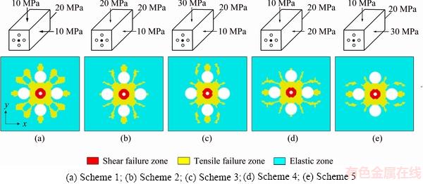
Fig. 11 Simulation results of prime cutting blasting under anisotropic high in-situ stresses
4) Tensile cracks are propagated in the direction of the maximum horizontal principal stress axis and are suppressed in the direction of the minimum horizontal principal stress axis in areas of pre-existing anisotropic high in-situ stresses.
References
[1] BALLAND C, MOREL J, ARMAND G, PETTITT W. Ultrasonic velocity survey in Callovo-Oxfordian argillaceous rock during shaft excavation [J]. International Journal of Rock Mechanics and Mining Sciences, 2009, 46(1): 69-79.
[2] LIU Xi-ling, LUO Ke-bing, LI Xi-bing, LI Qi-yue, WANG Wei-hua, GONG Feng-qiang. Cap rock blast caving of cavity under open pit bench [J]. Transactions of Nonferrous Metals Society of China, 2017, 27(3): 648-655.
[3] ORESTE P, SPAGNOLI G, LO B L. A combined analytical and numerical approach for the evaluation of radial loads on the lining of vertical shafts [J]. Geotechnical and Geological Engineering, 2016, 34(4): 1057-1065.
[4] SHATERPOUR-MAMAGHANI A, BILGIN N. Some contributions on the estimation of performance and operational parameters of raise borers��A case study in Kure Copper Mine, Turkey [J]. Tunnelling and Underground Space Technology, 2016, 54(1): 37-48.
[5] VENKATESH H S, BALACHANDER R, GUPTA R N. Handling the blockades while excavating the surge shaft at Tala Hydroelectric Project [J]. Tunnelling and Underground Space Technology, 2008, 23(2): 145-150.
[6] LI Qi-yue, LI Xi-bing, FAN Zuo-peng, ZHANG Rui-hua. One time deep hole raise blasting technology and case study [J]. Chinese Journal of Rock Mechanics and Engineering, 2013, 32(4): 664-670. (in Chinese)
[7] ZARE S, BRULAND A. Comparison of tunnel blast design models [J]. Tunnelling and Underground Space Technology, 2006, 21(5): 533-541.
[8] LI Ting-chun, LIU Hong-qiang, WANG Chao. Study of millisecond blasting technology of shaft excavation by one-step deep-hole blasting [J]. Rock and Soil Mechanics, 2012, 33(6): 1742-1746. (in Chinese)
[9] ZHOU Chuan-bo, GU Ren-guo, LUO Xue-dong. Numerical simulation on cutting mode of shaft excavation by one-step deep-hole blasting in hard rock [J]. Chinese Journal of Rock Mechanics and Engineering, 2005, 24(13): 2298-2303. (in Chinese)
[10] XIE L X, LU W B, ZHANG Q B, JIANG Q H, WANG G H, ZHAO J. Damage evolution mechanisms of rock in deep tunnels induced by cut blasting [J]. Tunnelling and Underground Space Technology, 2016, 58: 257-270.
[11] KIM J G, SONG J J. Abrasive water jet cutting methods for reducing blast-induced ground vibration in tunnel excavation [J]. International Journal of Rock Mechanics and Mining Sciences, 2015, 75: 147-158.
[12] ZHOU Chuan-bo, WANG Peng, LEI Yong-jian, YIN Xiao-peng. Optimization on cut-hole of mining tunnel excavation [J]. Mining Science and Technology, 2009, 19(1): 70-73.
[13] ZHAO Z, ZHANG Y, BAO H. Tunnel blasting simulations by the discontinuous deformation analysis [J]. International Journal of Computational Methods, 2011, 8(2): 277-292.
[14] SOROUSH K, MEHDI Y, ARASH E. Trend analysis and comparison of basic parameters for tunnel blast design models [J]. International Journal of Mining Science and Technology, 2015, 25(4): 595-599.
[15] QIAO D. Theoretical model and numerical analysis of millisecond delay time of parallel cut blasting in tunneling excavation [J]. Tunnelling and Underground Space Technology, 2006, 21(3-4): 386-391.
[16] YIN Tu-bing, SHU Rong-hua, LI Xi-bing, WANG Pin, DONG Long-jun. Combined effects of temperature and axial pressure on dynamic mechanical properties of granite [J]. Transactions of Nonferrous Metals Society of China, 2016, 26(8): 2209-2219.
[17] ZHOU Zi-long, CAI Xin, ZHAO Yuan, CHEN Lu, XIONG Cheng, LI Xi-bing. Strength characteristics of dry and saturated rock at different strain rates [J]. Transactions of Nonferrous Metals Society of China, 2016, 26(7): 1919-1925.
[18] LI Xi-bing, CHEN Shou-ru, GU De-sheng. Dynamic strength of rock under impulse loads with different stress waveforms and durations [J]. Journal of Central-South Institute of Mining Metallurgy, 1994, 25(3): 301-304. (in Chinese)
[19] LI X B, LOK T S, ZHAO J. Dynamic characteristics of granite subjected to intermediate loading rate [J]. Rock Mechanics and Rock Engineering, 2005, 38(1): 21-39.
[20] BISCHOFF P H, PERRY S H. Compressive behaviour of concrete at high strain rates [J]. Materials and Structures, 1991, 24(6): 425-450.
[21] TEDESCO J W, ROSS C A. Strain-rate-dependent constitutive equations for concrete [J]. Journal of Pressure Vessel Technology, 1998, 120(4): 398-405.
[22] GROTE D L, PARK S W, ZHOU M. Dynamic behavior of concrete at high strain rates and pressures: I. experimental characterization [J]. International Journal of Impact Engineering, 2001, 25(9): 869-886.
[23] CAI M, KAISER P K, SUORINENI F, SU K. A study on the dynamic behavior of the Meuse/Haute-Marne argillite [J]. Physics and Chemistry of the Earth (Parts A/B/C), 2007, 32(8-14): 907-916.
[24] YILMAZ O, UNLU T. Three dimensional numerical rock damage analysis under blasting load [J]. Tunnelling and Underground Space Technology, 2013, 38: 266-278.
[25] ZHAO J. Construction and utilization of rock caverns in Singapore. Part A: The Bukit Timah granite bedrock resource [J]. Tunnelling & Underground Space Technology, 1996, 11(1): 65-72.
[26] HOEK E, BROWN E T. The Hoek-Brown failure criterion��A 1988 update [C]// Proceedings of the 15th Canadian Rock Mechanics Symposium-In Rock Engineering for Underground Excavations. Toronto: University of Toronto Press, 1988: 31-38.
[27] HOEK E, BROWN E T. Practical estimates of rock mass strength [J]. International Journal of Rock Mechanics and Mining Sciences, 1997, 34(8): 1165-1186.
[28] SAHARAN M R, MITRI H S. Numerical procedure for dynamic simulation of discrete fractures due to blasting [J]. Rock Mechanics and Rock Engineering, 2007, 41(5): 641-670.
[29] CHO S H, KANEKO K. Influence of the applied pressure waveform on the dynamic fracture processes in rock [J]. International Journal of Rock Mechanics and Mining Sciences, 2004, 41(5): 771-784.
[30] ZHANG Z X. Rock fracture and blasting: Theory and applications [M]. Oxford: Butterworth-Heinemann, Elsevier, 2004: 334-352.
[31] KUTTER H K, FAIRHURST C. On the fracture process in blasting [J]. International Journal of Rock Mechanics and Mining Science, 1971, 8(3): 181-202.
[32] WENG Lei, HUANG Lin-qi, TAHERI A, LI Xi-bing. Rockburst characteristics and numerical simulation based on a strain energy density index: A case study of a roadway in Linglong gold mine, China [J]. Tunnelling and Underground Space Technology, 2017, 69: 223-232.
[33] WENG Lei, LI Xi-bing, TAHERI A, WU Qiu-hong, XIE Xiao-feng. Fracture evolution around a cavity in brittle rock under uniaxial compression and coupled static�Cdynamic loads [J]. Rock Mechanics and Rock Engineering, 2017, 51(2): 1-15.
������1���� ��1����Ϧ��1������ΰ1���� ��2
1. ���ϴ�ѧ ��Դ�밲ȫ����ѧԺ����ɳ 410083��
2. �人��ѧ ��ľ����ѧԺ���人 430072
ժ Ҫ����ֱ���Ͳ�һ�γɾ������У��Ͳ۲�����ѡ����Ͳ۵Ľ��Ӱ��ܴ�������ֵģ�ⷽ���о��Ͳ۲�������L�Ϳտ�ֱ��D���Ͳ۱����ƻ����Ĺ�ϵ��ͨ���û��Զ����ӳ�������һ���ƻ�״ָ̬�� �ã����������Ͳ۱���ѹ���ƻ����������ƻ�����ͬʱ�������1 �ͦ�2������ӳ�Ͳ۱���Ч����ָ�ꡣģ��������������һ������ֵ���L��ʹ����ָ���1�ͦ�2ͬʱ�ﵽ���ţ����Ͳ�Ч����ѡ�ͬʱ����L��������ֵʱ���տ�ֱ��DԽ���Ͳ�Ч��Խ�á����⣬�о�Ӧ���������ʺ͵�Ӧ�������Ͳ۱���Ч����Ӱ�죬���ָ����ʵ�ըҩ�������Ͳ۱��ƣ����������Ƶ���չ����ͳ����ܵ�Ӧ��������Ӧ����С�ͷ����Ӱ�졣
�ؼ��ʣ��쾮��������Ͳۿױ��ƣ���ֵģ�⣻�Ͳ۲����Ż���������
(Edited by Wei-ping CHEN)
Foundation item: Projects (2016YFC0600706, 2016YFC0600802) supported by the National Key Research and Development Program of China; Project (2017zzts186) supported by Cultivating Excellent Doctors of Central South University, China
Corresponding author: Kai LIU; Tel: +86-15116336350; E-mail: lkeason@csu.edu.cn
DOI: 10.1016/S1003-6326(18)64780-6

