剪切状态下锚杆变形加载角与位移角的关系
来源期刊:中国有色金属学报(英文版)2017年第4期
论文作者:陈瑜 曹平 周科平 滕云
文章页码:876 - 882
关键词:锚杆;剪切;位移角;加载角
Key words:steel rock bolt; shear; displacing angle; loading angle
摘 要:在工程现场中,当锚杆处于剪切加载状态时,其在靠近加载点的位置会产生弯曲变形。在锚杆变形过程中,节理位移相应增大,并在杆体内部诱发法向拉力与横向剪力。本文作者对剪切状态下锚杆变形加载角与位移角的解析关系进行分析,通过考虑锚杆剪切过程中的弹性状态与塑性状态,锚杆段的扭转角可由解析方法导出,因此基于位移角相应求出加载角。通过与文献中实验数据对比,证明了所推导的解析解的正确性与可行性。在实际工程中,可根据锚杆的轴向变形方向确定其加载力方向。
Abstract: When subjected to shear loading condition, a steel rock bolt will become bent in the field close to the loading point in situ. The bolt is deformed as the joint displacement increases, which can mobilize a normal load and a shear load on the bolt accordingly. In this work, the relationship analysis between the displacing angle and loading angle is carried out. By considering elastic and plastic states of rock bolt during shearing, the rotation of bolt extremity can be calculated analytically. Thus, the loading angle is obtained from displacing angle. The verification of analytical results and laboratory results from reference research implies that the analytical method is correct and working. In terms of in-situ condition, the direction of the load acting on steel bolt can be predicted well according to the direction of the deformed rock bolt with respect to original bolt axis.
Trans. Nonferrous Met. Soc. China 27(2017) 876-882
Yu CHEN1,2, Ping CAO1, Ke-ping ZHOU1, Yun TENG1
1. School of Resources and Safety Engineering, Central South University, Changsha 410083, China;
2. Department of Geology and Mineral Resources Engineering, Norwegian University of Science and Technology, Trondheim 7491, Norway
Received 14 January 2016; accepted 6 July 2016
Abstract: When subjected to shear loading condition, a steel rock bolt will become bent in the field close to the loading point in situ. The bolt is deformed as the joint displacement increases, which can mobilize a normal load and a shear load on the bolt accordingly. In this work, the relationship analysis between the displacing angle and loading angle is carried out. By considering elastic and plastic states of rock bolt during shearing, the rotation of bolt extremity can be calculated analytically. Thus, the loading angle is obtained from displacing angle. The verification of analytical results and laboratory results from reference research implies that the analytical method is correct and working. In terms of in-situ condition, the direction of the load acting on steel bolt can be predicted well according to the direction of the deformed rock bolt with respect to original bolt axis.
Key words: steel rock bolt; shear; displacing angle; loading angle
1 Introduction
The aim of all ground reinforcement techniques is to ensure the stability of an artificial structure constructed within or on a soil or rock mass by the installation of structural elements. Rock bolts have been used commonly for reinforcing relaxed zones around tunnels, caverns or other types of underground structures, and proved to be very effective. The effectiveness of a rock bolt system is dependent upon a better understanding of the load transfer mechanism between the rock-grout-bolt system and bolt interaction, particularly across the joints and shear planes that the bolt intersects [1-3].
Rock bolts were observed to suspend loose rock blocks detached from the rock mass by pinning them to the upper competent part of the rock mass structure. It was also observed that the reaction of the rock and/or grout, to the rock bolt deflection, resulted in the loading of the bolts axially. It is not the traditional understanding of bolt support as binding and suspending rock blocks, but the increase in shear strength of the jointed rock mass due to bolting. It was understood that bolts work as an additional resistance against shear failure along joints, hence, the entire rock mass becomes stronger and deforms less. Rock bolt was observed to be subjected of shear loading as a result of beam bending and slip along joints. It is also noted that installed rock bolt provided an additional resistance against shear failure along joints and weakness planes. Figure 1 [4] shows this rock bolt behavior. When a bolted rock joint is subjected to shearing, the bolt is deformed as the joint displacement increases, which can mobilize a normal load and a shear load on the bolt. The direction of the load applied to the rock bolt at a specific position is associated with the direction of the rock displacement vector at that position. The performance of rock bolts both in the laboratory and in the field has been examined by a number of studies [5-8]. Previous shear tests of rock bolts mainly aimed to study their effect on the reinforcement of rock joints.
Based on the experimental results, some researchers conducted theoretical studies on the mechanical performance of reinforced joints [9-15].  [12] provided an analytical solution based on the equilibrium of loads and estimated the contribution to the increase in strength. The mode of failure in the surrounding materials was neglected, which is a limitation. DIGHT [13] assumed that the bolt contribution to the strength of a sheared joint is a result of the tensile load and a perpendicular load to the bolt. If the location of the plastic hinge is known, a load- displacement curve may be drawn. HOLMBERG [14] investigated the performance of the bolt and a theoretical relation between bolt resistance and deformation was derived. By using failure criteria for the bolt, the maximum resistance and maximum deformation were determined. FERRERO [15] suggested two failure mechanisms of a bolted joint: a failure due to the combination of the axial and shear loads acting at the bolt-joint intersection and a failure due to the axial load after the formation of two plastic hinges symmetrically with respect to the shear plane. This mechanism is applicable for weaker rock.

Fig. 1 Installed rock bolts providing resistance against shear failure (after MOYO and STACEY [4])
The main objectives of these studies are the determination of bolt contribution to the shear joint strength and calculation of the joint displacement. According to their studies, the axial and shear loads, as well as the large plastic displacements of the bolt can be predicted. Based on the existing research, this paper focuses on the relationship analysis between the displacing angle and loading angle, which was not clearly pointed out in the previous study. It will improve understanding of shearing anchorage problems encountered in mining and civil engineering.
2 Illustration of loads acting on steel bolt subjected to shear
Rock bolts can suspend loose rock blocks detached from the rock mass by pinning them to the upper competent part of the rock mass structure, which is defined as the so-called suspension effect. Such suspension condition results in the axial loading of the bolt. Once a rock bolt is subjected to shear displacement from a known direction in situ, the bolt is deformed and the material surrounding the bolt (i.e., grout or rock) provides a reaction at the same time. This rock bolt mechanism is observed in cases where movement takes place along joints, thus, it is in combination with shear loading, as shown in Fig. 2 [4]. When a bolted joint is subjected to shear, the amount of bending is directly proportional to the applied load. In the majority of cases, the shear load on the rock bolt is greater with increasing deformation of the rock mass. This means that as the amount of the bending increases, the rock bolt curvature will increase.
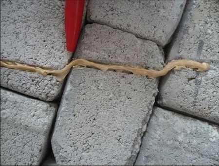
Fig. 2 Illustration of combination of load and bending for rock bolt in physical model (after MOYO and STACEY [4])
Figure 3 shows that the rock bolt is axially and transversely loaded by a set of loading actions including axial load (N), shear load (Q), and bending moment (M). There are two special points existing on the bolt via previous research [6,8]. One point is the intersection between the joint and the rock bolt (Point O) where the curvature of the deformed shape of the bolt is zero. It can be confirmed according to the beam theory that the bending moment at this point is zero. Therefore, only axial and shear loads act in the bolt extremity. The other point is the point of the maximum curvature (Point A) where the bending moment is the greatest and the shear load is zero accordingly. The so-called plastic hinge is developed at Point A.
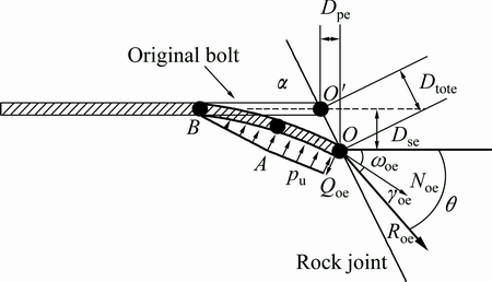
Fig. 3 Illustration of loads acting on bolt subjected to shear loading in elastic state (modified after PELLET and EGGER [8])
When the applied load increases, the surrounding material (i.e., grout or rock) supplies a reaction, pu. It acts on the length of the bolt and increases progressively until the bolt yields. The ultimate failure of the rock bolt can be determined by the combination of normal and transversal loads acting at Point O or by the combination of the axial load and the bending moment acting at Point A, where the moment is the greatest and the shear load is zero. It has been evaluated by others [16] that the relation between the resultant loads mobilized in the bolt and the associated joint displacement presents non-linearity. This is partially due to the yielding of the bolt steel and the rock and partially due to the development of large displacement. These two types of non-linearities, i.e., the elastic state and the plastic state, lead to the study of the bolt equilibrium in two phases.
PELLET and EGGER [8] have proposed an analytical model of a rock bolt subjected to shear loading conditions. According to their study, the axial and shear loads mobilized in the bolt, as well as the large plastic displacements of the bolt that occur during the loading process can be predicted. However, the relationship between the displacing angle and loading angle was not an important aspect of their study. The relationship was not clearly pointed out, even though these two relevant components can be predicted accordingly. In this paper, the displacing angle and the loading angle are defined and studied analytically. These two angles are further discussed with the help of the analytical model of rock bolts proposed by PELLET and EGGER [8]. The following chapter describes some analytical equations to evaluate the relationship between displacing angle and loading angle.
3 Analysis of relationship between loading angle and displacing angle in bolt shearing
3.1 Elastic state
Based on the beam theory, the distribution of normal stresses on any cross section is uniform with a single influence from the axial load on the bolt. As shown in Fig. 3, the bolt is considered as a beam of semi-infinite length, loaded at its end by shear load (Qo). It is assumed that the behavior of the surrounding material is perfectly rigid-plastic, and that the reaction pressure is constant until the point with maximum bending moment (Point A). It is also assumed that the anchoring length of the bolt is sufficient to avoid any failure by pull-out strength.
If there is only the axial load acting on the bolt, the distribution of normal stresses on any cross-section is uniform. The relationship among the normal stress, bending moment, and axial load can be expressed as
 (1)
(1)
where MA is the moment at Point A; W is the moment inertia of the bolt; No is the normal force acting at bolt extremity; A is the area of the bolt cross section.
The bending moment (MA) can be expressed as a function of the shear load (Qo):
 (2)
(2)
 (3)
(3)
 (4)
(4)
where Db is the bolt diameter.
It should be noted that the reaction from surrounding material is normal to the bolt, therefore, the friction at the bolt-grout interface is neglected and the axial load along the deformed length of the bolt is constant.
The relationship between axial and shear loads forms at Point O when the bolt reaches its elastic limit (Fig. 3) [9]. If M is replaced by Eq. (2), the relation between axial load (Noe) and shear load (Qoe) can be developed when the external fiber reaches elastic limit at Point A:
 (5)
(5)
where Qoe is the shear load at the bolt extremity and the elastic limit; Noe is the axial load at the bolt extremity at the elastic limit; σel is the elastic limit of the bolt material.
When a rock bolt is laterally loaded, it is assumed that the response from the surrounding material depends on the mechanical properties of the rock mass. It should be noted that the grout material is insignificant as the grout annulus is relatively small compared with the thickness of the rock mass. The UCS of the rock mass is normally used for the calculation of its bearing capacity. This is reasonable, as this value is commonly determined in association with underground constructions. A simple expression of bearing capacity is
pu=σcDb (5)
The displacing angle (α), i.e., the angle between the direction of the total displacement and the bolt axis, can be expressed using Dse and Dpe (Fig. 3):
 (7)
(7)
Expressions for axial and shear displacements can be obtained by minimization of total complementary energy [9]. Accordingly, the relation between them is obtained for the bolt in elastic condition:
 (8)
(8)
where β is the initial angle between the bolt and joint surface. b=0.27 [9].
Thus, the elastic limit can be defined by shear load Qoe. It is related to other parameters through the following third-order equation:
 (9)
(9)
The solution of this equation implies the axial load and shear load at the bolt extremity. As the loads acting in the bolt are known, the rotation (ωoe) in elastic state can be expressed as
 (10)
(10)
3.2 Plastic state
The bolt failure criterion may be established by considering the action of the axial load, Nof, and the shear load, Qof. The equation about the combination can be expressed as
 (11)
(11)
where Nof is the axial load at the bolt extremity at failure; Qof is the shear load at the bolt extremity at failure; Qy is shear bolt load corresponding to the yield strength.
According to Tresca’s criterion for steel material, the yield stress in tension may be two times of that in simple shear. Therefore, the values of axial load and shear load can be obtained:
 (12)
(12)
 (13)
(13)
where σec is the yield limit of the bolt material.
After the elastic limit of the bolt steel material is reached at the point of maximum bending moment (Point A), the bolt starts to yield and plastic hinges are progressively developed. In the plastic state, the bending stiffness of the bolt drops due to the influence of plastic hinges. Some assumptions for further calculation have been proposed [9]: 1) the positions of the plastic hinges are fixed with respect to the x axis; 2) the deformed shape of the bolt between Points O and A is linear; and the axial strain is constant along section OA.
As the elastic limit is reached, the value of the bending moment at Point A (Fig. 4) does not further increase, and the shear load remains constant until failure:
Qof=Qoe (14)
The axial load (Nof) at the failure is obtained by calculation with the involved failure criterion. If the failure occurs at Point O, the axial load can be expressed by combination of the axial and shear loads:
 (15)
(15)
As the deformed shape of the bolt between Point O and Point A is linear (Fig. 4), the displacement and the rotation at the bolt extremity were calculated by taking into account the large displacement formulation. The increment of the plastic rotation angle, at Point O ωop, is

 (16)
(16)
where εf is the Bolt material strain at failure.
Fig. 4 Load actions on bolt subjected to shear loading in plastic state (modified after PELLET and EGGER [8])
Since the bolt strain at failure is equal to the sum of the elastic and the plastic strains, the total rotation (ωof) of the bolt extremity at failure is calculated:
ωof=ωoe+ωop (17)
As indicated in Fig. 4, Rof is defined as the total failure load with respect to the axis of the rotated rock bolt at Point O and γof is defined as the angle between the total failure load and the deformed axis of the rock bolt. γof can be expressed by the axial load (Nof) and shear load (Qof) at the bolt extremity at failure:
 (18)
(18)
The sum of γof and the rotation angle wof, i.e., gof +wof, gives the angle of the total load Rof with respect to the original axis of the rock bolt. In other words, the loading angle can be expressed as
θ=γof+ωof (19)
Hence, the analytical relationship between the loading angle θ and the displacing angle α in bolt shearing can be determined according to Eqs. (1)-(19).
4 Verification of laboratory tests
A series of rock bolt tests, conducted with new test rig and developed method, were performed by CHEN and LI [16-18]. The variations of the displacing angle, α, and the loading angle, θ, of the bolts that were tested at different applied displacing angles and block strengths are presented in Fig. 5 [17]. These two angles fluctuate greatly at the beginning, but they soon stabilize until failure. The fluctuations of the angles are caused by the unstable loading conditions at the beginning of the test. In general, loading angle θ is smaller than displacing angle α. For instance, the displacing angles α of these tests were controlled by the test rig and kept constant at 60° (Figs. 3(b) and (d)). The magnitudes of the pull and shear loads were recorded during testing and the loading angles θ were calculated afterwards. It is interesting to note that the loading angle θ stabilized soon after the fluctuation. The ultimate value of the loading angle was about 30°. Similar variations occurred for the other bolt specimens.
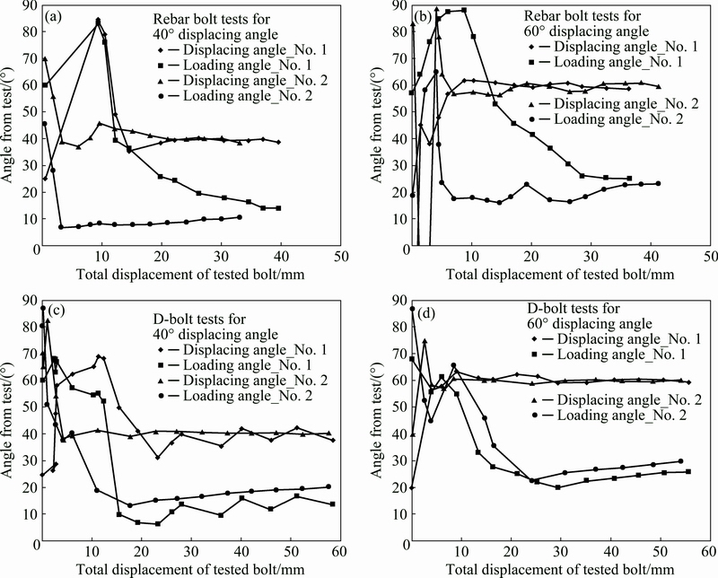
Fig. 5 Variations of displacing angle α and loading angle θ of D-bolts and rebar bolts during testing [17]
Table 1 Comparison of loading angles for analytical results and test results of strong concrete block (110 MPa) [17]
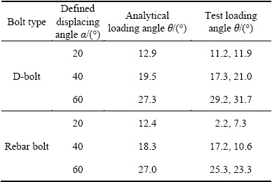
By considering the parameters of rock bolt, grout and rock mass from the laboratory tests presented above, the loading angles are calculated analytically according to Eqs. (1)-(19). The loading angles θ obtained from the bolt tests are also presented. The calculated results and the test results of loading angle for the tested bolts at failure are compared in Table 1. It can be seen that they agree very well, except for the rebar bolts tested with a displacing angle of 20°. Thus, it can be said that the calculated loading angle in the analytical model is approximately equal to the loading angle θ recorded and calculated during laboratory tests. The loading angle θ is a function of displacing angle α, which implies that loading angle can be determined from the displacing angle for a rock bolt subjected to shear loading via the above analytical solutions:
θ=f(α) (20)
Therefore, the presented method is working for the in-situ condition. If the direction of the deformed rock bolt with respect to original bolt axis is known in situ, the direction of the resultant load of the bolt can be calculated analytically.
5 Conclusions
1) When a rock bolt is subjected to shear displacement from in situ, the bolt is deformed and the surrounding material provides a reaction to the bolt. It acts on the length of the bolt and increases progressively until the bolt yields. The rock bolt is axially and transversely loaded by a set of loading actions including axial load, shear load and bending moment. This is partially due to the yielding of the bolt steel and the rock and the development of large displacement.
2) The displacing angle and the loading angle are defined and studied analytically. Two types of non-linearity, i.e., the elastic and plastic states, lead to the study of the bolt equilibrium. The rotations at the bolt extremity for these two states can be calculated individually. By comparing with the results obtained from the laboratory bolt tests, it is shown that the analytical results can be predicted well. The loading angle is smaller than the displacing angle. In conclusion, the loading angle can be determined from the displacing angle for a rock bolt subjected to shear loading via the analytical solutions. In case of in-situ condition, the direction of the resultant load of the bolt can be calculated only if the direction of the deformed rock bolt with respect to original bolt axis is measured.
Acknowledgments
The corresponding author acknowledges with grateful thanks to the Norwegian University of Science and Technology (NTNU) for providing the fund for this research work and the supervision from Prof. Charlie C. Li at NTNU.
References
[1] BOBET A, EINSTEIN H H. Tunnel reinforcement with rockbolts [J]. Tunnelling and Underground Space Technology, 2011, 26(1): 100-123.
[2] JALALIFAR H, AZIZ N, HADI M. The effect of surface profile, rock strength and pretension load on bending behaviour of fully grouted bolts [J]. Geotechnical and Geological Engineering, 2006, 24(5): 1203-1227.
[3] STILLBORG B. Professional users hands for rock bolting[M]. 2nd ed. Zurich: Trans Tech Publications, 1994: 117-122.
[4] MOYO Y, STACEY T R. Mechanisms of rockbolt support in jointed rock masses [C]//Proceedings of the Sixth International Seminar on Deep and High Stress Mining 2012. Perth, Australia: ACG, 2012: 91-97.
[5] SONG H, DUAN Y, YANG J. Numerical simulation on bolted rock joint shearing performance [J]. Mining Science and Technology, 2010, 20(3): 460-465. (in Chinese)
[6] SPANG K, EGGER P. Action of fully-grouted bolts in jointed rock and factors of influence [J]. Rock Mechanics and Rock Engineering, 1990, 23(3): 201-229.
[7] LIU B, YUE Z Q, THAM L G. Analytical design method for a truss-bolt system for reinforcement of fractured coal mine roofs-Illustrated with a case study [J]. International Journal of Rock Mechanics and Mining Sciences, 2005, 42(2): 195-218.
[8] PELLET F, EGGER P. Analytical model for the mechanical behaviour of bolted rock joints subjected to shearing [J]. Rock Mechanics and Rock Engineering, 1996, 29(2): 73-97.
[9] PELLET F. Strength and deformability of jointed rock masses reinforced by rock bolts [D]. Zurich: Swiss Federal Institute of Technology, 1994.
[10] GRASSELLI G. 3D Behaviour of bolted rock joints: Experimental and numerical study [J]. International Journal of Rock Mechanics and Mining Sciences, 2005, 42(1): 13-24.
[11] JALALIFAR H, AZIZ N. Analytical behaviour of bolt-joint intersection under lateral loading conditions [J]. Rock Mechanics and Rock Engineering, 2010, 43(1): 89-94.
[12] S. Shear strength of hard rock joints reinforced by grouted untensioned bolts [C]//Proceedings of the 3rd International Congress on Rock Mechanics. Denver, USA: 1974: 1194-1199.
[13] DIGHT P M. Improvements to the stability of rock walls in open pit mines [D]. Melbourne: Monash University, 1982.
[14] HOLMBERG M. The mechanical behaviour of untensioned grouted rocks bolts [D]. Stockholm: Royal Institute of Technology, 1991.
[15] FERRERO A M. The shear strength of reinforced rock joints [J]. International Journal of Rock Mechanics and Mining Sciences and Geomechanics Abstracts, 1995, 32(6): 595-605.
[16] CHEN Y, LI C C. Performance of fully encapsulated rebar bolts and D-bolts under combined pull-and-shear loading [J]. Tunnelling and Underground Space Technology, 2015, 45: 99-106.
[17] CHEN Y, LI C C. Influences of loading condition and rock strength to the performance of rock bolts [J]. Geotechnical Testing Journal, 2015, 38(2): 207-218.
[18] CHEN Y. Experimental study and stress analysis of rock bolt anchorage performance [J]. Journal of Rock Mechanics and Geotechnical Engineering, 2014, 32(5): 428-437.
陈 瑜1,2,曹 平1,周科平1,滕 云1
1. 中南大学 资源与安全工程学院,长沙 410083;
2. Department of Geology and Mineral Resources Engineering, Norwegian University of Science and Technology, Trondheim 7491, Norway
摘 要:在工程现场中,当锚杆处于剪切加载状态时,其在靠近加载点的位置会产生弯曲变形。在锚杆变形过程中,节理位移相应增大,并在杆体内部诱发法向拉力与横向剪力。本文作者对剪切状态下锚杆变形加载角与位移角的解析关系进行分析,通过考虑锚杆剪切过程中的弹性状态与塑性状态,锚杆段的扭转角可由解析方法导出,因此基于位移角相应求出加载角。通过与文献中实验数据对比,证明了所推导的解析解的正确性与可行性。在实际工程中,可根据锚杆的轴向变形方向确定其加载力方向。
关键词:锚杆;剪切;位移角;加载角
(Edited by Wei-ping CHEN)
Foundation item: Projects (51604299, 51274249, 51474252) supported by the National Natural Science Foundation of China; Project (2016YFC0600706) supported by the State Key Research Development Program of China; Project (2015CX005) supported by the Innovation Driven Plan of Central South University, China; Project (2016M600636) supported by China Postdoctoral Science Foundation; Project supported by the Postdoctoral Science Foundation of Central South University, China
Corresponding author: Yu CHEN; E-mail: yu.chen@csu.edu.cn
DOI: 10.1016/S1003-6326(17)60101-8

