Combustion characteristics of supersonic strut-cavity combustor under plasma jet-assisted combustion
��Դ�ڿ������ϴ�ѧѧ��(Ӣ�İ�)2021���1��
�������ߣ�ϯ���� �ņ� ����
����ҳ�룺311 - 324
Key words��plasma jet; strut; cavity; supersonic combustion; numerical simulation; combustion efficiency
Abstract: Plasma jet has been widely used in supersonic combustor as an effective ignition and combustion assisted method, but currently it is mostly combined with the traditional wall fuel injection method, while the application combined with the central fuel injection method is less. In order to expand the combustion range, the plasma jet was introduced into a strut-cavity combustor with an alternating-wedge. The effects of total pressure of strut fuel injection, total pressure of cavity fuel injection, total pressure of plasma jet injection and plasma jet media on the combustion characteristics were analyzed in supersonic flow by numerical calculations in a three-dimensional domain. The combustion field structure, wall pressure distribution, combustion efficiency and distribution of H2O at the exit of the combustor with different injection conditions were analyzed. The results show that the combustion efficiency decreases with the increase of the strut fuel injection total pressure. However, the combustion area downstream increases when the total pressure of the strut fuel injection increases within the proper range. The combustion range is expanded and the combustion efficiency is improved when the cavity fuel injection total pressure is increased within the range of 0.5-2.0 MPa, but a sharp drop in combustion efficiency can be found due to limited fuel mixing when the total injection pressure of the cavity fuel is excessively increased. With the increased total injection pressure of the plasma jet, the height of the cavity shear layer is raised and the equivalence ratio of the gas mixture in the cavity is improved. When the total pressure of the plasma jet is 1.25 MPa, the combustion efficiency reaches a maximum of 82.1%. The combustion-assisted effect of different plasma jet media is significantly different. When the medium of the plasma jet is O2, the combustion-assisted effect on the combustor is most significant.
Cite this article as: ZHANG Zhe, JIN Xing, XI Wen-xiong. Combustion characteristics of supersonic strut-cavity combustor under plasma jet-assisted combustion [J]. Journal of Central South University, 2021, 28(1): 311-324. DOI: https://doi.org/10.1007/s11771-021-4604-2.

J. Cent. South Univ. (2021) 28: 311-324
DOI: https://doi.org/10.1007/s11771-021-4604-2

ZHANG Zhe(�ņ�)1, JIN Xing(����)1, XI Wen-xiong(ϯ����)2
1. State Key Laboratory of Laser Propulsion & Application, Space Engineering University,Beijing 101416, China;
2. School of Aeronautics and Astronautics, Central South University, Changsha 410083, China
 Central South University Press and Springer-Verlag GmbH Germany, part of Springer Nature 2021
Abstract: Plasma jet has been widely used in supersonic combustor as an effective ignition and combustion assisted method, but currently it is mostly combined with the traditional wall fuel injection method, while the application combined with the central fuel injection method is less. In order to expand the combustion range, the plasma jet was introduced into a strut-cavity combustor with an alternating-wedge. The effects of total pressure of strut fuel injection, total pressure of cavity fuel injection, total pressure of plasma jet injection and plasma jet media on the combustion characteristics were analyzed in supersonic flow by numerical calculations in a three-dimensional domain. The combustion field structure, wall pressure distribution, combustion efficiency and distribution of H2O at the exit of the combustor with different injection conditions were analyzed. The results show that the combustion efficiency decreases with the increase of the strut fuel injection total pressure. However, the combustion area downstream increases when the total pressure of the strut fuel injection increases within the proper range. The combustion range is expanded and the combustion efficiency is improved when the cavity fuel injection total pressure is increased within the range of 0.5-2.0 MPa, but a sharp drop in combustion efficiency can be found due to limited fuel mixing when the total injection pressure of the cavity fuel is excessively increased. With the increased total injection pressure of the plasma jet, the height of the cavity shear layer is raised and the equivalence ratio of the gas mixture in the cavity is improved. When the total pressure of the plasma jet is 1.25 MPa, the combustion efficiency reaches a maximum of 82.1%. The combustion-assisted effect of different plasma jet media is significantly different. When the medium of the plasma jet is O2, the combustion-assisted effect on the combustor is most significant.
Key words: plasma jet; strut; cavity; supersonic combustion; numerical simulation; combustion efficiency
Cite this article as: ZHANG Zhe, JIN Xing, XI Wen-xiong. Combustion characteristics of supersonic strut-cavity combustor under plasma jet-assisted combustion [J]. Journal of Central South University, 2021, 28(1): 311-324. DOI: https://doi.org/10.1007/s11771-021-4604-2.
1 Introduction
Different types of combustors play a very important role in their respective fields [1], and the flame position [2] and combustion characteristics [3] of combustors have also been hot issues in the research of different types of combustors, especially the scramjet engine which has received much attention in recent years. With the increased Mach number of hypersonic vehicle, in the combustor of scramjet engines, the combustion organization has more severe problems. The period that the fuel stays in the combustor is within milliseconds [4].
Therefore, it is very difficult to achieve fuel mixing, combustion and heat release in such a short time. This is also the most direct problem faced in supersonic combustor.
To solve this problem, the first method is to add structures, such as struts, ramps and cavities in the combustor to change the local flow field, to create a region conducive to ignition and combustion [5, 6]. The strut injector can inject fuel into the central area of the combustor, effectively extending the penetration depth of the fuel. At the same time, the oblique shock wave in the front, the recirculation zone and streamwise vortices at the trailing can promote fuel mixing. The cavity can integrate fuel injection, mixing and flame stabilization, which is a flame stabilization device widely used recently. Therefore, the combustor combined with the cavity and the strut has received a lot of attention.
GRADY et al [7] found through numerical simulation that the strut has the advantages of enhancing the air flow inside the cavity and accelerating the development of the shear layer in the cavity. ZHAO et al [8] studied the cold flow field under the coupling of the cavity and the strut by experiments, and found that the interaction between the shock wave and the cavity shear layer can increase the area of the recirculation zone to a certain extent, which is helpful to achieve the flame stabilization in the combustor. HSU et al [9] found that combining the strut injector with the cavity structure could improve the ignition ability of the combustor and promote flame stabilization. SATHIYAMOORTHY et al [10] investigated the kerosene combustion in the strut-cavity combustor by experiments. A new cavity structure with ventilated rear wall is proposed, and it is found that this structure can effectively attenuate pressure oscillations and promote flame stabilization. LI et al [11] investigated a new solid rocket scramjet equipped with a strut and two cavities by experimental and numerical approaches. The results show that combination of strut and cavity helps to achieve fuel mixing and flame stability. SUNEETHA et al [12] studied the implication of the strut profile on the combustion characteristics of the strut-cavity combustor. MIAO et al [13] found that the combination of cavity and strut may weaken the ignition performance under certain circumstances, but the combination can improve flame stability. SONG et al [14] studied the effects of different fuel injection methods in a round strut-cavity combustor, and the result shows that the fuel injection method has a great influence on the combustor performance, and also affects the flow field structure.
As another method is to assist ignition, the plasma jet is the most effective one among them [15]. The plasma jet mainly assists ignition and combustion through the following three aspects. This is also the advantage of plasma jet in ignition and combustion of supersonic combustor.
In terms of thermal effects, the temperature of the plasma jet in supersonic combustion is extremely high, so it can release heat in the combustor to promote the ignition of the fuel [16]. For aerodynamic effects, plasma jets can change the local flow field structure of the combustor and then improve the mixing and distribution of fuel [17]. The plasma jet contains a certain amount of active components, which can participate in the ignition and the combustion of the fuel and then improve the combustion efficiency. [18].
Plasma jet to supersonic flow was introduced for the first time in 1981 by KIMURA et al [19]. They studied the effects of plasma jet on the combustion of hydrocarbon fuel. TAKITA et al [20] used oxygen, nitrogen, and argon as plasma jet medium to conduct ignition and flame stabilization studies under supersonic flow. The results showed that the different free radicals in the plasma jet can also affect the combustion to a certain extent and increase the combustion area. At the same time, it is found that the equivalent ratio of the gas mixture near the plasma jet area is directly related to the flame stability. MURAKAMI et al [21] studied the combustion-assisted effect of plasma jet media in the case of an incoming flow of Mach 2.3, and the results showed that the use of O2 as the jet media is more favorable for ignition and combustion. When the plasma jet nozzle is located downstream of the fuel nozzle, it is easier to achieve flame stabilization. Subsequently, TAKITA et al [22] experimentally studied a dual plasma jet with the incoming flow of supersonic. The result shows that the combustion performance of using a dual plasma jet is not much different from that of a single plasma jet, and fuel combustion is more affected by the upstream plasma jet.
WEI et al [23] conducted experimental works on two fuels, ethylene and hydrogen. Under the condition of supersonic flow, the plasma jet has a good performance in shortening the fuel ignition delay time and improving the ignition performance. DUAN et al [24] studied the effects of plasma jet on supersonic combustor through experimental research. It is shown that the frequency of plasma jet has a certain effect on the combustion mode. Research work by LIU et al [25] showed that the use of plasma jet can help to avoid fuel accumulation near the cavity, and then promote the mixing of the fuel and enhance flame stability.
On the basis of this, DOU et al [26] continually investigated the effects of different equivalence ratios on the combustion efficiency and flow field characteristics of supersonic combustors under plasma jet combustion.
For the numerical works of supersonic combustion, MASUYA et al [27] found that the electron and ion content are relatively small in the plasma jet used in the supersonic combustor, which has little effect on the ignition and combustion of the fuel. This provided the initial theoretical basis for the simplification of the plasma jet. Based on this work, MINATO et al [28] replaced the plasma jet model by a high temperature jet model containing a certain concentration of O atoms, which can well reflect the influence of plasma jets at different temperatures on combustion.
WEI et al [23] conducted experiments with a simplified plasma jet in a steady-state high temperature nitrogen molecular stream. The results verify the validity of this numerical method for the study of the influence of plasma jet on the ignition process of hydrogen. SONG et al [29] used a hydrogen jet model with an ionization degree of 0.5% to simplify the plasma jet. The same method also can be found [25].
In previous studies, plasma jet has been proven to be a very effective ignition and combustion assisted method in supersonic combustor. However, most of them are combined with wall injection methods such as transverse jet and aerodynamic ramp, while the application with central fuel injection is relatively few. The combustor coupled with the strut and the cavity is also widely used as a device to enhance fuel mixing and maintain flame stability, especially the alternating-wedge strut, because its unique tailing structure can induce streamwise vortices to enhance the mixing of fuel, which has also become a research hotspot.
In order to expand the combustion range of the combustor, the traditional plasma jet combined with the wall injection method is introduced into the strut-cavity combustor with alternating-wedge structure. On this basis, the combustion characteristics of methane under the joint action of plasma jet and central fuel injection strut-cavity combustor are studied by three-dimensional numerical simulation method. The combustion characteristics with different plasma jet and fuel injection parameters are obtained and analyzed.
2 Approaches and methods
2.1 Geometric model
The combustor model used in this work is shown in Figure 1, which contains three sections: the isolation section, the combustion section and the diverging section. The height and width of the combustor entrance are 70 and 50 mm, respectively. Both the lower wall and the upper wall of the combustion section have an expansion angle of 2��, and the upper wall of the diverging section also has an expansion angle of 2��.
As shown in Figure 1, the strut injector is located in the front of the cavity, and is arranged perpendicular to the lower wall. The strut is 36 mm from the entrance of the combustion section. The plasma jet nozzle is located on the lower wall of the cavity.
Due to the limited length of the combustor, the fuel injected by the strut injector is difficult to interact with the plasma jet in the cavity in a short distance. Therefore, a fuel injection nozzle perpendicular to the lower wall of the cavity is added in front of the plasma jet nozzle. The fuel injected by this nozzle first interacts with the plasma jet forms a guiding flame in the cavity and propagates downstream to ignite the fuel downstream and to extend the combustion range to the entire combustor.
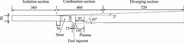
Figure 1 Structure of combustor (Unit: mm)
The strut injector used in this work is an alternating-wedge strut and the streamwise vortices generated at the trailing helps to expand the fuel distribution range. Four fuel injection nozzles with a diameter of 3 mm are located at the trailing of the strut and arranged at equal intervals. The plasma jet nozzle and fuel injection nozzle in the cavity are 30 and 15 mm from the front wall of the cavity, respectively, and the diameter of the injection holes is 3 mm. The remaining parameters are shown in Figure 2.

Figure 2 Structure of strut (Unit: mm)
2.2 Computational model
The RANS numerical methods are used in this work. Among them, the SST k-�� model is selected as the continuous phase turbulence model. This model retains the original k-�� model near the wall region, which is helpful for solving the boundary layer problem, and the standard k-�� model is used in the area far from the wall. The specific governing equation is as follows [30]:
Mass conservation equation:
 (1)
(1)
Momentum conservation equation:
 (2)
(2)
Energy equation:
 (3)
(3)
Turbulent kinetic energy (k) equation:
 (4)
(4)
Energy dissipation equation (��):

 (5)
(5)
The eddy-viscosity is defined as
 (6)
(6)
where ��, ui, p, ��ij, Fbi, Q, �� and vt are density, component velocity, pressure, turbulent shear stress, mass component force, main body heating, vorticity, and eddy-viscosity; F1 and F2 are mixed functions and depend on the distance from the point to the wall; a1, ��k, ����, ��*, �� and �� are the coefficients of the turbulence model, which can be obtained by the formula ��=F1��1+(1-F1)��2 [31].
2.3 Boundary conditions
The combustor parameter selected in the paper is 6 which is based on the flight Mach number. The Mach number of the combustor entrance is 3.0 with a total pressure of 2.11 MPa, a static pressure of 50 kPa, and a static temperature of 702 K.
The injection speed of the fuel injection nozzles is sonic. The injected fuel is methane with a total temperature of 300 K. The total temperature of the plasma jet is 3000 K, the mole fraction of O atom is 0.02, and the plasma jet nozzle is a sonic nozzle. The wall conditions for all the walls and struts are assumed as the no-slip conditions. The chemical reaction uses a 7-step, 9-component reaction model of methane.
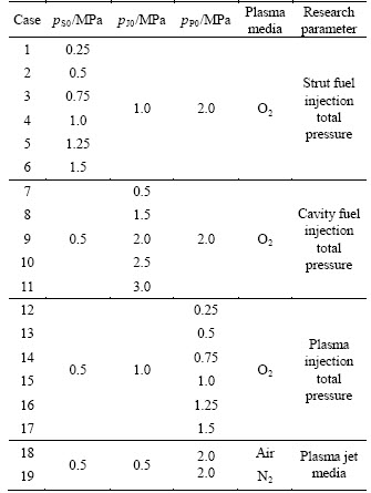
In this work, the influence of the strut fuel injection total pressure, the cavity fuel injection total pressure, the plasma injection total pressure, and the plasma jet medium on the combustion characteristics are analyzed through three- dimensional numerical simulation. The injection parameters of different cases are shown in Table 1.
The initial conditions are as follows: the gauge pressure is 50 MPa, the velocity in the incoming direction is 1600 m/s, and the temperature is 702 K.
Table 1 Different fuel and plasma injection parameters
2.4 Example verification
The meshes of computational domain of the combustor are generated by the ANSYS ICEM module. At the trailing of the struts, due to the coupling of cylindrical nozzles and alternating- wedge structures, an unstructured meshing method is used, and the remaining areas are divided into structured meshes. The grids of the injection nozzles, the wall, and the cavity are encrypted. The thickness of the first layer of the boundary layer is 0.01 mm.
In order to confirm the grid independence, the simulation was performed under the total fuel injection pressure of 1.0 MPa and the total plasma injection pressure of 1.5 MPa. Three different grid scales of the computational domain are generated: the coarse mesh (0.9��106 cells), the moderate mesh (2.0��106 cells), and the refined mesh (2.6��106 cells).
Figure 3 shows the H2O mass fraction of combustor exit under different grid scales. It shows that the H2O mass fraction curve under different mesh scales agrees well, and the gap between the moderate mesh and the refined mesh is significantly smaller than that between the coarse mesh and the moderate mesh. So, the moderate mesh model is selected in this work.
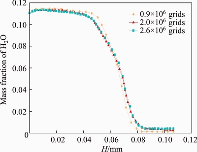
Figure 3 H2O mass fraction of combustor exit under different grid scales
To ensure the accuracy of the selected numerical method, the same numerical method was used to simulate the supersonic combustion experiment performed by YU et al [32]. The selected combustor was the Combustor model 1 in the literature, in which the inclination of the cavity is 45 �� and the length is 79 mm.
The numerical results are shown in Figure 4. The red solid squares are the experimental results obtained by YU et al [32], and the blue dotted lines represent the numerical calculation results. It shows that the numerical calculation results are in good agreement with the static pressure change trend in the experiment. The numerical calculation results in the fact that the downstream of the combustor is slightly larger than the experiment results. However, the overall results of the numerical calculations can more accurately reflect the experimental results, this also verifies the effectiveness of the numerical methods.
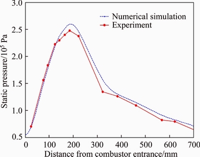
Figure 4 Comparison of experiment and numerical calculation results
3 Results and analysis
3.1 Effects of strut fuel injection total pressure on combustion characteristics
The H2O mass fraction contour on the central section under different strut fuel injection total pressure is shown in Figure 5. It can be seen that the H2O concentration between the plasma jet nozzle and the rear wall of the cavity is the highest, which is the region with the most intense combustion reaction.
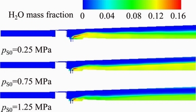
Figure 5 H2O mass fraction contour on central section under different strut fuel injection total pressure
When the strut fuel injection total pressure is small, the fuel can be fully mixed with incoming flow, and sufficient combustion can be achieved in the area above the rear wall of the cavity. Therefore, the concentration of H2O near the position above the rear wall of the cavity is the highest, and the distribution altitude is also the highest. As the fuel is consumed, the H2O concentration gradually decreases downstream of the combustor. When the total injection pressure is increased to 0.75 MPa, the H2O concentration in the area above the rear wall of the cavity is slightly reduced, but the H2O concentration and distribution height are increased to a certain extent downstream of the combustor. When the total injection pressure is continually increased to 1.25 MPa, the fuel injected by the strut injector is difficult to achieve a good mixing and the H2O concentration in the entire combustor is significantly reduced.
Figure 6 shows the static temperature contour on the central section under different strut fuel injection total pressure, which shows a similar trend to the distribution of H2O mass fraction in Figure 5. When the strut fuel injection total pressure is small, the range of the high temperature area is the largest near the cavity. As the injection pressure increases, the high static temperature area near the cavity decreases, but there is a certain increase in the high temperature area downstream. When the strut fuel injection total pressure is increased to 1.25 MPa, the high temperature region of the entire combustor is reduced to a certain extent.
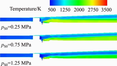
Figure 6 Static temperature contour on the central section under different strut fuel injection total pressure
Figure 7 shows the Mach number contour on the central section under different strut fuel injection total pressure. It shows that when the total strut injection pressure is 0.25 MPa, the subsonic combustion region is mainly concentrated in the cavity and the lower wall of the combustor. When the total injection pressure is increased to 0.75 MPa, the area of the subsonic combustion area near the cavity is reduced, while the subsonic area near the lower wall of the combustor is slightly increased. When the total injection pressure is continually increased to 1.25 MPa, the overall subsonic region of the combustor showed a decreasing trend.
To study the three-dimensional characteristics of the distribution of combustion products, eight planes perpendicular to the direction of the incoming flow are selected with equal intervals behind the strut to analyze the distribution of H2O.
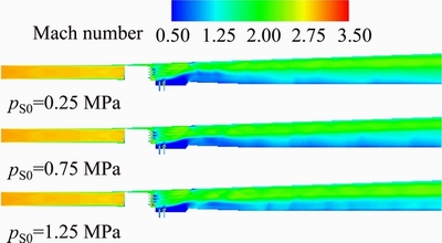
Figure 7 Mach number contour on central section under different strut fuel injection total pressure
Figure 8 shows the H2O mass fraction contour of the combustor under different strut fuel injection total pressure. As the total strut fuel injection pressure increased from 0.25 to 0.75 MPa, the distribution height of H2O in the cavity decreased, and the distribution range of H2O in the downstream of the combustor does not change much, while the concentration is significantly increases. When the total strut fuel injection pressure increased, the distribution height and concentration of H2O in the cavity shows a certain downward trend, and the concentration and distribution height of H2O in the downstream of the combustor are significantly reduced.

Figure 8 H2O mass fraction contour of combustor under different strut fuel injection total pressure
The fuel and air mixing are limited due to the increased injected fuel, which affects the combustion of the fuel and reduces the combustion area in the combustor.
Figure 9 shows the H2O mass fraction curve at the combustor exit under different total strut fuel injection pressure. The distribution of H2O at the outlet of the combustor generally shows a similar distribution trend. In the range of 0.25-0.75 MPa, with the increased fuel injection total pressure, the peak value of the H2O mass fraction continues to increase, and the downward position of the curve moves to the right, indicating that the distribution height of H2O is increased. This is because the fuel mixing is not restricted, and as the fuel injected by the strut increases, the combustion range of the entire combustor also increases. When the total pressure reaches 1 MPa, the peak value of H2O mass fraction at the combustor exit decreases when the strut fuel injection pressure is increased which can cause the limitation of fuel mixing. The downward position of the curve moves to the left, indicating that the distribution height of H2O at the combustor exit is reduced. Because when the total injection pressure reaches 1.0 MPa, the fuel injected by the strut is too much to form an equivalent ratio suitable for ignition and combustion. On the contrary, it affects the combustion in the combustor, so the H2O distribution at the outlet is closer to the lower wall.
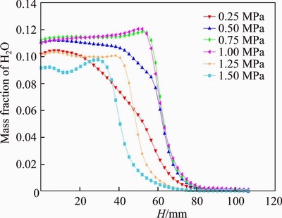
Figure 9 H2O mass fraction curve at combustor exit under different strut fuel injection total pressure
To quantitatively study the combustion efficiency under different injection parameters, the combustion efficiency is expressed as the percentage of fuel consumed in the current section. The calculation formula is as follows:
 (7)
(7)
Among them, MCH4 is the mass flow rate of fuel injected by the strut fuel injection nozzles and the cavity fuel injection nozzle. Based on this, the combustion efficiency at different sections can be calculated. In this work, the combustion efficiency at the combustor exit is selected for analysis.
Figure 10 shows the combustion efficiency at the combustor exit under different total strut fuel injection pressure. With the increased strut fuel total injection pressure, the combustion efficiency shows a decreased trend, because the fuel and the plasma jet in the cavity are constant, and the increase of the total strut injection pressure does not affect the combustion in the cavity. Instead, the overall fuel in the combustor is increased. From the previous analysis, it can be seen that before the total injection pressure is 1 MPa, the fuel can achieve sufficient mixing, and the overall downward trend in combustion efficiency is relatively gentle. When the total pressure reaches 1.25 MPa, the fuel efficiency is significantly reduced due to the obvious obstruction of fuel mixing. When the strut fuel injection total pressure is 1.5 MPa, the combustion efficiency of the combustor exit is reduced to 46.2%. This is because the fuel injected by the strut is too much, and it is difficult to fully mix in a short time, thereby affecting the combustion in the combustor.
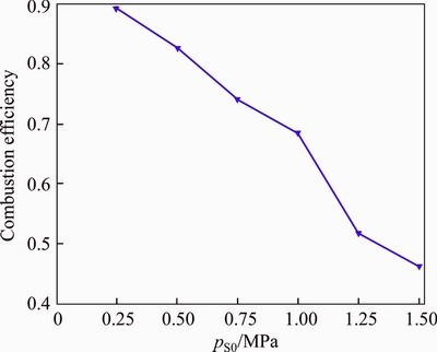
Figure 10 Combustion efficiency at combustor exit under different total strut fuel injection pressures
3.2 Effects of cavity fuel injection total pressure on combustion characteristics
Figure11 shows the H2O mass fraction contour under different cavity fuel injection total pressure. When the cavity fuel injection total pressure is 0.5 MPa, i.e., less fuel enters the cavity, this part of the fuel can achieve sufficient combustion. Therefore, the H2O concentration in the cavity is the highest and the distribution range is the widest. As the cavity fuel injection total pressure increases to 1.5 MPa, the H2O concentration in the cavity decreases. For this case, due to the fact that the high injection total pressure raises the cavity shear layer, the flame in the cavity is easier to propagate downstream and then the distribution height of H2O downstream of the combustor is also increased.
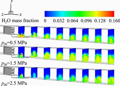
Figure 11 H2O mass fraction contour under different cavity fuel injection total pressure
When the total cavity fuel injection pressure is increased to 2.5 MPa, the H2O concentration of the combustor shows a significant downward trend. This is due to the fact that the fuel and air mixing in the cavity is restricted due to too much injected fuel, so it is difficult to achieve sufficient combustion of the fuel in the cavity, which also affects the downstream combustion. Therefore, excessive increase of the total injection pressure of the cavity fuel is not suitable for the combustion of the combustor.
Figure 12 shows the H2O mass fraction curve at the combustor exit under different cavity fuel injection total pressure. Overall, the distribution of water components is mainly concentrated near the lower wall. Within the range of 0.5-2.0 MPa, the maximum H2O mass fraction at the combustor exit increases gradually as the injection total pressure increases. When the injection total pressure is 1.5 and 2.0 MPa, the H2O mass fraction in the range near the upper wall is also stable above 0.01, which also indicates that the combustion reaction at this time is the most intense.
But then, the maximum mass fraction and distribution range of water components decreased significantly. Especially when the total fuel injection pressure reached 3.0 MPa, a certain concentration of H2O appeared only at the position close to the lower wall, and the maximum H2O mass fraction is also significantly lower when the total injection pressure was low. This indicates that there is too much fuel in the cavity, and it is impossible to achieve a proper mixture equivalent ratio, and the combustion area of the combustor is reduced to the area near the lower wall.
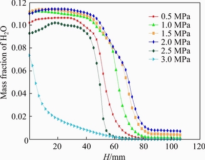
Figure 12 H2O mass fraction curve at combustor exit under different cavity fuel injection total pressure
Figure 13 shows the wall pressure distribution curve under different cavity fuel injection total pressure. It shows that the wall pressure curves before the cavity are almost coincident, which indicates that the flow field upstream of the combustor is not affected by the combustion downstream. At the position of 460 mm, the oblique shock wave is generated due to the interaction between the strut injector and the incoming flow, which causes a significant jump in wall pressure. Above the rear wall of the cavity, due to the heat of combustion, the pressure here also increases significantly. Subsequently, the wall pressure also shows a certain downward trend since the air flow expands in the diverging section.
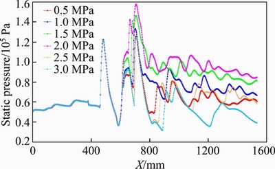
Figure 13 Wall pressure distribution under different total pressure of cavity fuel injection
Before the cavity fuel injection total pressure reaches 2.0 MPa, as the total injection pressure increases, the wall pressure increases, because the fuel and plasma jet in the cavity can be fully mixed at this time, and the equivalent ratio suitable for combustion is reached, and the shear layer of the cavity is also raised, which is beneficial to the propagation of the flame downstream. Therefore, the wall pressure curve of the entire combustor rises accordingly; when the total injection pressure reaches 2.5 and 3 MPa, although the fuel injection lifts the shear layer of the cavity, due to too much fuel in the cavity, the equivalent ratio suitable for ignition and combustion cannot be achieved. The combustion is significantly weakened in the cavity, affecting the combustion of the entire combustor. This is also consistent with the aforementioned H2O distribution range.
Figure 14 shows the combustion efficiency at combustor exit under different cavity fuel injection total pressure. The combustion efficiency curve shows the same trend as the wall pressure curve and the H2O distribution. Before the total injection pressure is 1.5 MPa, the fuel injected in the cavity can be fully mixed. Therefore, as the total injection pressure increases, the flame generation in the cavity is better promoted, and the combustion efficiency is improved. The combustion efficiency increased significantly with the increase of the fuel injection total pressure, and reached more than 90% when the total pressure is 1.5 and 2.0 MPa.
Figure 14 Combustion efficiency at combustor exit under different cavity fuel injection total pressure
Then, by increasing the total cavity fuel injection pressure, the combustion efficiency tends to decrease rapidly. Especially when the injection pressure is 3 MPa, the mixing of the fuel in the cavity is significantly limited, and the combustion efficiency at the outlet drops below 40%. This is also consistent with the results reflected by the wall static pressure curve in Figure 13.
3.3 Effects of plasma jet injection total pressure on combustion characteristics
The introduction of plasma jet into the strut-cavity combustor can lift the cavity shear layer on the one hand, which is conducive to the downstream development of the cavity flame. On the other hand, the plasma jet medium used in this section is O2. With the increased injection total pressure, the O2 concentration in the cavity increases, and the equivalent ratio is also improved, which has benefits for the occurrence of combustion in the cavity.
Figure 15 shows the H2O mass fraction contour under different plasma injection total pressure. When the plasma jet is not introduced, the combustion area is closely adjacent to the lower wall and the cavity in the combustor. When the total pressure of the plasma jet is small, on the one hand, the lifting effect on the shear layer of the cavity is limited; on the other hand, the equivalence ratio suitable for ignition and combustion cannot be achieved in the cavity. At this time, the distribution of H2O is mainly concentrated on the lower wall too. However, due to the action of the plasma jet, the distribution height of H2O is still improved to a certain extent compared with the case when the plasma jet is not added.
Figure 15 H2O mass fraction contour under different plasma injection total pressure
With the increase of the plasma injection total pressure, the distribution range and concentration of H2O in the cavity are increased, and the distribution range of H2O in the downstream combustor is also significantly improved. When the plasma injection total pressure is increased to 1.5 MPa, the concentration of water components in the cavity is significantly increased. However, in the downstream of the combustor, the distribution range and concentration of H2O are not significantly improved compared to the case when the total injection pressure is 1.0 MPa.
Figure 16 shows the H2O mass fraction curve at the combustor exit under different plasma injection total pressure. It shows that the introduction of the plasma jet significantly increases the distribution range and height of H2O. The distribution of H2O is mainly concentrated near the lower wall, and the H2O mass fraction near the upper wall is almost 0. This is also consistent with the H2O mass fraction contour in Figure 15.
Figure 16 H2O mass fraction curve at combustor exit under different plasma injection total pressure
When the plasma injection total pressure is 0.5 MPa, the maximum value of H2O mass fraction is greater than 0.12, and the maximum value of H2O mass fraction under the other total pressures is maintained around 0.11. The distribution curve shows a trend of maintaining the same and then gradually decreases. When the total pressure of plasma jet is less than 1.25 MPa, with the increased total pressure, the distribution height of H2O at the combustor exit increases, and the downward position of the curve moves to the right. Then, the curve becomes stable with the increased total pressure. It indicates that the fuel in the cavity has been fully burned, and continuing to increase the total injection pressure has little effect on the combustion.
Figure 17 shows the wall pressure distribution curve under different plasma injection total pressure. The wall pressure curve almost coincides before the position of cavity, and the wall pressure curve behind the cavity shows a similar change trend, but the wall pressure curves under different total injection pressures are also different. Comparing the wall pressure distribution curves of different conditions, it shows that in the range of 0.25-1.25 MPa, the wall pressure in the downstream of the combustor gradually increases when the total pressure of plasma jet increases. Under the condition that the fuel injected in the cavity is constant, increasing the total injection pressure of the plasma jet can promote the lifting of the shear layer and accelerate the flame propagation; on the other hand, it can also form an equivalent ratio suitable for ignition and combustion in the cavity. Therefore, the wall pressure increases as the total injection pressure increases.
Figure 17 Wall pressure distribution under different total pressure of plasma jet
However, when the plasma injection total pressure reaches 1.5 MPa, the wall pressure curve only increases significantly near the cavity, and the pressure curve downstream of the combustor only increases a little. This shows that the continuous increase of the plasma injection total pressure has little effect on the performance in the downstream. Because the fuel in the cavity is constant, after the fuel can be fully burned, simply increasing the total injection pressure of the plasma jet has little effect on promoting the combustion of the fuel in the cavity, so continuously increasing the plasma jet will cause unnecessary pressure loss.
Figure 18 shows the combustion efficiency at the exit under different injection total pressure of plasma jet. It shows that the introduction of the plasma jet improves the combustion efficiency significantly. At the same time, the combustion efficiency at the combustor exit generally shows a increased trend with the increase of the plasma injection total pressure.
When the total pressure of the plasma jet is in the range of 0.5-1.25 MPa, the combustion efficiency increases most significantly. When the total pressure is 1.25 MPa, the combustion efficiency reaches a maximum of 82.1%, and then

Figure 18 Combustion efficiency at combustor exit under different plasma injection total pressure
the increase of the total pressure of the plasma jet has little effect on the combustion efficiency. This is consistent with the previous analysis. The plasma jet promotes the combustion of the cavity fuel and the lifting effect of the cavity shear layer within a certain range, but it also needs to match the amount of fuel in the cavity. Otherwise, it will cause unnecessary pressure loss, but the improvement of combustion efficiency is not obvious.
3.4 Effects of plasma jet media on combustion characteristics
The H2O mass fraction contour on the central section with different plasma media is shown in Figure 19. When O2 is used as the plasma jet medium, the concentration and distribution height of H2O in the cavity are the highest, and the distribution range of H2O in the downstream of the combustor is also the widest.
When the plasma jet medium is N2, a certain concentration of H2O only appears in the area near the rear wall of the cavity. This is because when plasma jet media is N2, the fuel and air are diluted to a certain extent, which also affects the combustion of the fuel in the cavity.
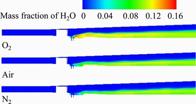
Figure 19 H2O mass fraction contour on central section with different plasma media
Figure 20 shows the static temperature contour on the central section with different plasma media, showing a similar trend to the distribution of H2O in Figure 19. When O2 is used as the medium of plasma jet, the combustion in the cavity is the most sufficient, and the distribution range of the high temperature region is the highest. In the process of downstream development, the high temperature region is also significantly higher than when the medium is N2 or air.

Figure 20 Static temperature contour on central section with different plasma media
Figure 21 shows the H2O mass fraction curve at the combustor exit with different plasma media. When the media of plasma jet is O2, the H2O mass fraction at the combustor exit is the largest and the downward position of the curve is to the right, indicating that the combustion area in the combustor is wider at this time and a higher concentration of H2O is generated. The distribution of water components also reflects the combustion status of the combustor. When O2 is used as the jet medium, the improvement of the equivalence ratio is the key to better combustion efficiency.
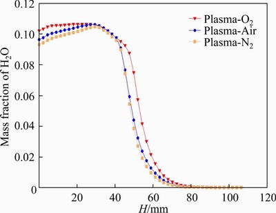
Figure 21 H2O mass fraction curve at combustor exit with different plasma media
From the perspective of the combustion efficiency defined in this paper, when O2 is used as the medium of plasma jet, the combustion efficiency at the combustor exit is 67.1%. It is significantly better than the combustion efficiency of 60.1% with the media of air and the combustion efficiency of 58.3% with the medium of N2.
4 Conclusions
In this work, a three-dimensional numerical study was conducted to investigate the combustion characteristics of the strut-cavity combustor. The combustion flow field under different fuel and plasma jet injection parameters are analyzed and compared. Some conclusions are shown below.
1) Increasing the strut fuel injection total pressure, the combustion area of the combustor shows a trend of increase firstly and then decrease. Due to the restriction of fuel mixing, the combustion efficiency is negatively related to the total injection pressure of the strut.
2) Increasing the cavity fuel injection total pressure in the range of 0.5-2.0 MPa can expand the combustion area in the combustor and improve the combustion efficiency. But when the cavity fuel injection total pressure increases to a certain extent, excessive increase of the total pressure causes a rapid decrease in combustion efficiency due to insufficient fuel mixing.
3) Introducing the plasma jet into the strut- cavity combustor has benefits to improve the combustion efficiency and expand the combustion area of the combustor. Increasing the total injection pressure of the plasma jet can raise the height of the shear layer in the cavity and improve the local gas-equivalent ratio and the combustion efficiency.
4) The media of plasma has a significant effect on the performance of the strut-cavity combustor. Based on the experimental conditions mentioned, the combustion efficiency is the highest and the combustion area is the largest when the medium of plasma jet is O2.
In the follow-up work, based on the investigation of the combustion characteristics, the ignition characteristics of the plasma jet combined with the strut-cavity combustor will be studied, and the structural design of the strut-cavity and the selection of plasma jet parameters will be further improved in conjunction with ground experiments. Based on the ground experiments, we continue to carry out multidisciplinary design optimization and orthogonal experimental design, thereby further optimizing the performance of the combustor under the assistance of the plasma jet.
Contributors
Investigation, numerical simulation, data analysis, and paper writing were carried out by ZHANG Zhe; XI Wen-xiong conceived and supervised the study and edited the manuscript; JIN Xing proofread and confirmed the results.
Conflict of interest
ZHANG Zhe, JIN Xing and XI Wen-xiong declare that they have no conflict of interest.
References
[1] PENG Qing-guo, YANG Wen-ming, E Jia-qiang, XU Hong- peng, LI Zhen-wei, YU Wen-bin, TU Yao-jie, WU Yi-feng. Experimental investigation on premixed hydrogen/air combustion in varied size combustors inserted with porous medium for thermophotovoltaic system applications [J]. Energy Conversion and Management, 2019, 200: 112086. DOI: 10.1016/j.enconman.2019.112086.
[2] PENG Qing-guo, E Jia-qiang, ZHANG Zhi-qing, HUA Wen-yu, ZHAO Xiao-huan. Investigation on the effects of front-cavity on flame location and thermal performance of a cylindrical micro combustor [J]. Applied Thermal Engineering, 2018, 130: 541-551. DOI: 10.1016/ j.applthermaleng.2017.11.016.
[3] E Jia-qiang, WU Jiang-hua, LIU Teng, CHEN Jing-wei, DENG Yuan-wang, PENG Qing-guo. Effects analysis on catalytic combustion characteristic of hydrogen/air in micro turbine engine by fuzzy grey relation method [J]. Journal of Central South University, 2019, 26(8): 2214-2223. DOI: 10.1007/s11771-019-4167-7.
[4] DING Meng, YU Yong, LIANG Ji-han, LIU Wei-dong, WANG Zhen-guo. Experimental investigation of ignition technology in liquid hydrocarbon fueled scramjet combustor [J]. Journal of Propulsion Technology, 2004, 25(6): 566-569. DOI: 10.3321/j.issn:1001-4055.2004.06.020. (in Chinese)
[5] TETLOW M, DOOLAN C. Comparison of hydrogen and hydrocarbon-fueled scramjet engines for orbital insertion [J]. Journal of Spacecraft and Rockets, 2007, 44(2): 365-373. DOI: 10.2514/1.24739.
[6] SUNAMI T, MURAKAMI A, KUDO K, KODERA M, NISHIOKA M. Mixing and combustion control strategies for efficient scramjet operation in wide range of flight mach numbers [C]// 11th AIAA/AAAF International Conference. 2002: 5116. DOI: 10.2514/ 6.2002-5116.
[7] GRADY N, PITZ R W, CARTER C D. Supersonic flow over a ramped-wall cavity flame holder with an upstream strut [J]. Journal of Propulsion and Power, 2012, 28(5): 982-990. DOI: 10.2514/1.B34394
[8] ZHAO Yan-hui, LIANG Jian-han, ZHAO Yu-xin. Non- reacting flow visualization of supersonic combustor based on cavity and cavity�Cstrut flameholder [J]. Acta Astronautica, 2016, 121: 282-291. DOI: 10.1016/j.actaastro.2015.12.040.
[9] HSU K, CARTER C, GRUBER M R, BARHORST T, SMITH S. Experimental study of cavity-strut combustion in supersonic flow[J]. Journal of Propulsion & Power, 2007, 26(6): 1237-1246. DOI: 10.2514/1.45767.
[10] SATHIYAMOORTHY K, DANISH T H, SRINIVA J, MANJUNATH P. Experimental investigation of supersonic combustion in a strut-cavity based combustor [J]. Acta Astronautica, 2018, 148: 285-293. DOI: 10.1016/j.actaastro. 2018.05.014.
[11] LI Chao-long, XIA Zhi-xun, MA Li-kun, ZHAO Xiang, CHEN Bin-bin. Experimental and numerical study of solid rocket scramjet combustor equipped with combined cavity and strut device [J]. Acta Astronautica, 2019, 162: 145-154. DOI: 10.1016/j.actaastro.2019.05.057.
[12] SUNEETHA L, RANDIVE P, PANDEY K M. Numerical investigation on implication of strut profile on combustion characteristics in a cavity based scramjet combustor [J]. Acta Astronautica, 2020, 170: 623-636. DOI: 10.1016/j.actaastro. 2020.02.025.
[13] MIAO Jun-jie, FAN Yu-xin. Influence of strut on cavity at subsonic speeds: Ignition characteristics [J]. Proceedings of the Institution of Mechanical Engineers, Part G: Journal of Aerospace Engineering, 2020: 0954410020904832. DOI: 10.1177/0954410019843726.
[14] SONG Wen-yan, ZHANG Dong-qing, SHI De-yong. Numerical study of combinations of strut and cavity in a round supersonic combustor [J]. International Journal of Turbo & Jet-Engines, 2019, 36(3): 219-231. DOI: 10.1515/ tjj-2016-0069.
[15] HONG Yan-ji, XI Wen-xiong, LI Lan, ZHANG Peng. Comments on researches of mechanism for plasma assisted combustion and applications in high speed flow-field [J]. Journal of Propulsion Technology, 2018, 39(10): 1-15. DOI: 10.13675/j.cnki.tjjs.2018.10.011. (in Chinese)
[16] JACOBSEN L S, CARTER C D, BAURLE R A. Toward plasma-assisted ignition in scramjets [J]. Journal of Propulsion and Power, 2008, 24(4): 641-654. DOI: 10.2514/6.2003-871.
[17] KIYOTAKA S, RYOICHI K, TAKESHIk T. Two-stage plasma torch ignition in supersonic airflows [C]// 37th Joint Propulsion Conference and Exhibit. 2001: 3740. DOI: 10.2514/6.2001-3740.
[18] MACHERET S, SHNEIDER M, MILES R. Energy efficiency of plasma-assisted combustion in ram/scramjet engines [C]// 36th AIAA Plasmadynamics and Lasers Conference. 2005: 5371. DOI: 10.2514/6.2005-5371.
[19] KIMURA I, AOKI H, KATO M. The use of a plasma jet for flame stabilization and promotion of combustion in supersonic air flows [J]. Combustion and Flame, 1981, 42: 297-305. DOI: 10.1016/0010-2180(81)90164-4.
[20] TAKITA K. Ignition and flame-holding by oxygen, nitrogen and argon plasma torches in supersonic airflow [J]. Combustion and Flame, 2002, 128: 301-313. DOI: 10.1016/ S0010-2180(01)00354-6.
[21] MURAKAMI K, NISHIKAWA A, TAKITA K. Ignition characteristics of hydrocarbon fuels by plasma torch in supersonic flow [C]// 12th AIAA International Space Planes and Hypersonic Systems and Technologies, 2003: 6939. DOI: 10.2514/6.2003-6939.
[22] TAKITA K, NAKANE H, MASUYA G. Optimization of double plasma jet torches in a scramjet combustor [J]. Proceedings of the Combustion Institute, 2007, 31: 2513-2520. DOI: 10.1016/j.proci.2006.07.054.
[23] WEI Bao-xi, OU Dong, YAN Ming-lei, XU Xu. Ignition and flame holding ability of plasma torch igniter in a supersonic flow [J]. Journal of Beijing University of Aeronautics and Astronautics, 2012, 38(12): 1572-1576. DOI: 10.13700/ j.bh.1001-5965.2012.12.022. (in Chinese)
[24] DUAN Li-wei, HONG Yan-ji. Effects of plasma torch jet frequency on supersonic combustion characteristics [J]. Journal of Propulsion Technology, 2015, 36(10): 1539-1546. DOI: 10.13675/j.cnki.tjjs.2015.10.014. (in Chinese)
[25] LIU Yi, DOU Zhi-guo, YANG Bo, ZHANG Peng. Experimental investigation on ignition of ethylene/air by plasma jet in supersonic combustor [J]. Journal of Propulsion Technology, 2017, 38(7): 1532-1538. DOI: 10.13675/j.cnki. tjjs.2017.07.012. (in Chinese)
[26] DOU Zhi-guo, LIU Yi, ZHANG Peng, YANG Bo. Effect of equivalence ratio on flow field and combustion characteristics of plasma ignition in supersonic combustor [J]. High Voltage Engineering, 2017, 43(12): 3981-3987. DOI: 10.13336/j.1003-6520.hve.20171127022. (in Chinese)
[27] MASUYA G, KUDOU K, MURAKAMI A. Some governing parameters of plasma torch igniter/flameholder in a scramjet combustor [J]. Journal of Propulsion and Power, 1993, 9(2): 176-181. DOI: 10.2514/3.23606.
[28] MINATO R, NIIOKA T, SUGIYAMA H, MIZOBATA K. Numerical analysis of supersonic combustion by a plasma torch [C]// AIAA/CIRA 13th International Space Planes and Hypersonics Systems and Technologies Conference. 2005: 3424. DOI: 10.2514/6.2005-3424.
[29] SONG Zhen-xing, HE Lin-ming, ZHANG Jian-bang, ZHAO Bing-bing, LIU Jian-xing. Three-dimensional numerical simulation of supersonic plasma ignition process [J]. High Power Laser and Particle Beams, 2012, 24(11): 2746-2750. DOI: 10.3788/HPLPB20122411.2746. (in Chinese)
[30] HUANG Wei, LI Shi-bin, LIU Jun, WANG Zhen-guo. Investigation on high angle of attack characteristics of hypersonic space vehicle [J]. Science China (Technological Sciences), 2012. DOI: 10.1007/s11431-012-4760-6.
[31] MENTER F. Zonal two equation k-w turbulence models for aerodynamic flows [C]// 24th Fluid Dynamics Conference. 1993: 2906. DOI: 10.2514/6.1993-2906.
[32] YU G, LI J G, CHANG X Y, CHEN L H, SUNG C J. Investigation of kerosene combustion characteristics with pilot hydrogen in model supersonic combustors [J]. Journal of Propulsion & Power, 2001, 17(6): 1263-1272. DOI: 10.2514/2.5874.
(Edited by FANG Jing-hua)
���ĵ���
��������������ȼ��֧�尼ǻȼ���ҵ�ȼ������
ժҪ����������������Ϊһ����Ч�ĵ����ȼ��ʽ�ڳ�����ȼ�����еõ��˹㷺��Ӧ�ã�����Ŀǰ�����봫ͳ�ı���ȼ����ע��ʽ���ϣ���������ȼ����ע��ʽ�Ľ�Ͻ��١�Ϊ������ȼ�շ�Χ�����Ľ������������������˴��н���βԵ�ṹ��֧��-��ǻȼ�����С�ͨ����ά��ֵ���㣬�о��˳�����������֧��ȼ����ע��ѹ����ǻȼ����ע��ѹ����������������ע��ѹ�͵��������������ʶ�ȼ�����Ե�Ӱ�죬�����˲�ͬ��ע�����µ�ȼ�ճ��ṹ����ѹ�ֲ���ȼ��Ч�ʺ�ȼ���ҳ���ˮ��ֵķֲ�������о����������ȼ��Ч������֧��ȼ����ע��ѹ�����Ӷ����ͣ������ں��ʵķ�Χ������֧��ȼ����ע��ѹʱ��ȼ�������ε�ȼ������Ҳ�������ӡ�����ǻȼ����ע��ѹ��0.5~2.0 MPa�ķ�Χ������ʱ��ȼ���ҵ�ȼ�������ȼ��Ч�ʶ������������������ȵ����Ӱ�ǻȼ����ע��ѹ������ȼ�ϵĻ�����ޣ�ȼ��Ч�ʼ����½������ŵ�������������ע��ѹ�����ӣ���ǻ���в�ĸ߶�̧������ǻ�ڵĻ���������Ҳ�õ����ƣ���Ч�شٽ���ȼ�ա�����������������ע��ѹΪ1.25 MPaʱ��ȼ��Ч�ʴﵽ��ߵ�82.1%����ͬ�������������ʵ���ȼЧ�����������IJ��졣�������������Ľ���ΪO2ʱ����ȼ���ҵ���ȼ������Ϊ���ԡ�
�ؼ��ʣ���������������֧�壻��ǻ��������ȼ�գ���ֵ���㣻ȼ��Ч��
Foundation item: Project(51606220) supported by the National Natural Science Foundation of China; Project(1194028) supported by the Beijing Natural Science Foundation, China
Received date: 2020-04-01; Accepted date: 2020-08-11
Corresponding author: XI Wen-xiong, PhD, Assistant Pesearcher; Tel: +86-13739076081; E-mail: 13739076081@163.com; ORCID: https://orcid.org/0000- 0001-5125-827X

