C5191磷青铜薄板超高速冲裁断面的显微组织特征
来源期刊:中国有色金属学报(英文版)2021年第3期
论文作者:胡道春 陈明和 王蕾 王红军
文章页码:692 - 702
Key words:C5191 phosphor bronze; ultra-high-speed blanking; blanked surface; adiabatic shear; dynamic recrystallization
摘 要:为了研究C5191磷青铜在超高速冲裁条件下的变形机制,借助DOBBY-OMEGA F1超高速冲床完成0.12 mm厚的C5191磷青铜板材在3000冲次/分条件下的超高速冲裁试验,并分别利用EBSD和TEM技术对冲裁断面进行显微组织表征。结果发现,冲裁断面区域晶粒沿着冲裁方向拉长排列,局部区域形成较强的{001}á100?立方织构(极密度分别为9和12)和次强的 织构(极密度分别为4和7);同时,冲裁断面的剪切带区域存在变形孪晶,并在冲裁挤压和局部温升效应下发生旋转、粗化,形成晶界清晰、具有大角度晶界的亚晶;C5191磷青铜薄板在超高速冲裁过程中发生绝热剪切,并伴随有动态再结晶产生。
Abstract: The deformation mechanism of C5191 phosphor bronze sheet under ultra-high-speed blanking was investigated. By virtue of a DOBBY-OMEGA F1 ultra-high-speed press, the ultra-high-speed blanking test was conducted on C5191 phosphor bronze sheets with a thickness of 0.12 mm at 3000 strokes per minute. The microstructures of the blanked edges were characterized and analyzed separately by electron back-scatter diffraction (EBSD) and transmission electron microscopy (TEM). The results show that grains in the blanked edges are stretched along the blanking direction. Strong {001}<100> cube textures (maximum pole densities of 9 and 12, respectively) and secondarily strong textures (maximum pole densities of 4 and 7, respectively) are formed in local zones. Additionally, deformation twins are found in the shear zone of the blanked edges which are rotated and coarsened due to the blanking-induced extrusion and local thermal effect which can further form into sub-grains with clear and high-angle boundaries. The C5191 phosphor bronze sheet is subjected to adiabatic shear during ultra-high-speed blanking, accompanied with dynamic recrystallization.
Trans. Nonferrous Met. Soc. China 31(2021) 692-702
Dao-chun HU1,2, Ming-he CHEN2, Lei WANG2,3, Hong-jun WANG1
1. Engineering Technology Training Center, Nanjing Vocational University of Industry Technology, Nanjing 210023, China;
2. Jiangsu Key Laboratory of Precision and Micro-Manufacturing Technology, Nanjing University of Aeronautics and Astronautics, Nanjing 210016, China;
3. School of Mechanical Engineering, Nanjing Vocational University of Industry Technology, Nanjing 210023, China
Received 3 March 2020; accepted 10 November 2020
Abstract: The deformation mechanism of C5191 phosphor bronze sheet under ultra-high-speed blanking was investigated. By virtue of a DOBBY-OMEGA F1 ultra-high-speed press, the ultra-high-speed blanking test was conducted on C5191 phosphor bronze sheets with a thickness of 0.12 mm at 3000 strokes per minute. The microstructures of the blanked edges were characterized and analyzed separately by electron back-scatter diffraction (EBSD) and transmission electron microscopy (TEM). The results show that grains in the blanked edges are stretched along the blanking direction. Strong {001}<100> cube textures (maximum pole densities of 9 and 12, respectively) and secondarily strong  textures (maximum pole densities of 4 and 7, respectively) are formed in local zones. Additionally, deformation twins are found in the shear zone of the blanked edges which are rotated and coarsened due to the blanking-induced extrusion and local thermal effect which can further form into sub-grains with clear and high-angle boundaries. The C5191 phosphor bronze sheet is subjected to adiabatic shear during ultra-high-speed blanking, accompanied with dynamic recrystallization.
Key words: C5191 phosphor bronze; ultra-high-speed blanking; blanked surface; adiabatic shear; dynamic recrystallization
1 Introduction
Metal workpieces in information technology (IT) devices including connector terminals in computer, communication and consumer electronics (3C) products, lead frames of integrated circuits, aerospace electrical connectors, and connectors for high-speed data transmission of car on internet in the era of big data. These workpieces are all characterized by ultra-thin thickness (lower than 500 μm), complex shapes, small sizes, high requirements on size and location precision (nearly micron-order) and high demand [1]. Products are required to integrate an increasingly number of functions and show high performance. They are becoming smaller, while exhibit more elaborated appearance and have a more frequent upgrading rate due to very high demand in the market. The workpieces have massive increasing demands on low-cost and good quality, which generally requires manufacturing in large quantities using high-speed and precision progressive stamping technology.
Blanking is considered as the most fundamental and frequently used process in high-speed and precision progressive stamping. It can not only be used to manufacture blanks in the early period for the subsequent processes such as bending and drawing, but also be used as the final process to directly shape and manufacture precise blanked parts. The blanked edges determine the quality of blanked parts. During the whole process of blanking, plastic deformation, fracture and separation of metal materials are only found in a localized zone around the cutting edges. The cutting edges were subjected to huge vertical and lateral pressures, and those high pressures will produce a large quantity of friction heat. Moreover, the blanking process continuously lasts for a long time, which results significant local temperature-rise and softening effect [2,3]. Additionally, the strain-rate hardening and strain hardening of materials under a high rate and large strain make the fracture mechanism of high-speed precise blanking more complex. Also, due to the constraints of service conditions (such as low fracture zones, short response time and difficulty in on-line detection), it is hard to quantitatively describe the characteristics of blanked edges.
MUCHA [4] and ACHOURI et al [5] separately acquired microstructures such as the size of grains on the blanked edges and the streamline distribution of metals. They found that the significant plastic deformation occurs and grains are greatly refined in the blanked edges. ISMAIL et al [6] obtained the curve of yield stress on the blanked edges of non-oriented silicon steel with a thickness of 0.65 mm at the blanking speed of SPM80 by using nano-indentation technology. The results indicated that significant work-hardening occurs in the zone around the blanked edges at a low blanking speed.
GAUDILLIERE et al [7] performed high- speed blanking (14.6 m/s) on C40 steel using the split Hopkinson pressure bar test, and observed an adiabatic shear band in the blanked edges. SAPANATHAN et al [8] found that ultra-fine grains (diameter of grains lower than 1 μm) appeared in the microzone of the edges after attaining a crystal orientation map of the blanked edges of aluminum/ copper composite materials using the electron back-scatter diffraction (EBSD) technology.
Using the finite element technology, RAFSANJANI et al [9] explored the temperature change of X30Cr13 steel in the blanking process (blanking clearance of c=10% and punching speed of V=1000 mm/s). They found that the local temperature of the blanked edges is as high as 387 °C. By numerically simulating the high-speed blanking process (thickness of t=0.12 mm, blanking clearance of c=6.5%t and punching speed of V=1000 mm/s) of C5191 phosphor bronze sheets, HU et al [10] demonstrated that the local temperature of the blanked edges reaches 444 °C. Local temperature rise has a significant effect on the fracture damage induced by blanking and microstructures of the blanked edges.
Current research further systematically explores various aspects of blanking such as macroscopic blanked edge quality and numerical simulation to deepen the understanding on high-speed blanking. However, it is difficult to profoundly and effectively analyze the blanking mechanism as little is known about the control and effects of microstructures that play critical roles on the localization of macroscopic deformation during blanking. In this study, the microstructural characteristics of the blanked edges and their evolution were investigated by conducting high-speed blanking tests. The results provide a basis for exploring the fracture mechanism of sheets during high-speed blanking.
2 Experimental
2.1 Preparation of blanking samples
To describe the preparation process of the blanking samples for micro-measurements, the blanking sample is illustrated in Fig. 1. Based on the micro-measurement of the blanked edges, the microstructure evolution of shear zone under different blanking conditions was analyzed (Zone I). The microscopic evolution of materials from the blanked edges to the matrix was analyzed based on the longitudinal section perpendicular to the direction of the blanked edges (Zone II).
2.2 Preparation of EBSD samples
EBSD technology is an effective method that can be used to determine crystal structure, orientation and related crystallographic information of samples. The diffraction Kikuchi band excited by electron beams emitted from the SEM on the surface of inclined samples was analyzed [11,12]. The orientation analysis based on EBSD technology can acquire abundant information on the inner structure of crystals. It is common that only grain size, shape and distribution can be attained from microstructural and morphological images. Even though the image is processed using an image analysis system, only the quantitative information on morphology can be obtained. In contrast, in addition to diverse information on morphology, orientation imaging microscopy (OIM) can acquire various types of quantitative information such as grain orientation, phase distribution, grain (phase) boundary type, strain distribution and dislocation density [13,14]. EBSD technology can demonstrate more information compared with direct observations. This information is crucial for comprehensively exploring the deformation law and microscopic mechanism of materials.
Due to the requirement of the surface roughness requirement of samples in the EBSD test, the samples failed to be prepared in Zone I. To acquire the microstructures of deformed materials in Zone II on the blanked edges, blanking strips were cut and embedded in conductive inlay powder, as shown in Fig. 2. The ends (marked in Fig. 2(a)) of the embedded samples all corresponded to the cutting planes (Fig. 2(b)) of the blanked edges. The surface stress layer was removed using twin-jet electropolishing after being mechanically polished. The scanning area of EBSD was 15 μm from the blanked edges, as shown in Fig. 2(b). The EBSD test was completed using a JSM-7001F/JEOL field emission scanning electron microscope equipped with EBSD.
2.3 Preparation of samples for TEM test
To test and analyze the microstructures of the blanked edges, and further discuss the evolution law of microstructures during blanking, two sample preparation methods were adopted. TEM samples perpendicular to the blanked edges (for observing microstructural changes from the blanked edges to the material matrix) and parallel to the edges (for observing the microstructures of the shear zone) were attained respectively, as shown in Fig. 3.
When preparing TEM samples perpendicular to the blanked edge, a disk with d1.5 mm was first obtained at the proper location of the blanked strip, as shown in Fig. 3(a). The blanked edges of two semicircular samples were bonded (bonding the shear zone with the shear zone) and fixed using copper rings (Fig. 3(b)). The blanked strip was subjected to one-way selective thinning by applying a Gatan PIPS-691 ion milling, firstly from the shear zone along the fracture zone and then from the direction of the roll over zone. In this process, the position was broken down due to thinning in the shear zone (Fig. 3(b)). Finally, the microzone for the TEM test was situated within the red border area in Fig. 3(c) to acquire the TEM morphologies of four local microzones, near the shear zone, adjacent to the shear zone, adjacent to the matrix, and in the matrix. To ensure that the positions of the microzones (box zone) in different blanked strips for TEM test were consistent, the same parameter setting was adopted during one-way selective ion-thinning.
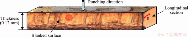
Fig. 1 Schematic map of blanking sample
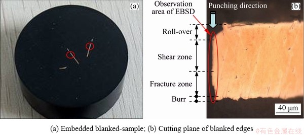
Fig. 2 Preparation of samples for EBSD analysis
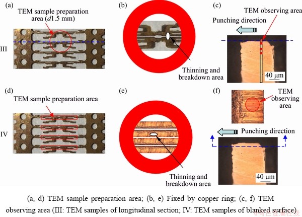
Fig. 3 Preparation of TEM samples
To reveal the evolution of the microstructures in shear zones on the blanked edges at different punching speeds, TEM samples parallel to the blanked edges were prepared by referring to the preparation method [15] according to the following process: multiple samples were cut from the blanked strips that were 3 mm in length and about 0.3 mm in width, as shown in the red border area of Fig. 3(d) (the blanked edge cannot be damaged). Multiple samples were bonded with (G1) glue to ensure evenness of the blanked edges and fixed using copper rings (Fig. 3(e)). The blanked strips were subjected to one-way selective thinning using the Gatan PIPS691 ion beam thinner, only from the opposite of the blanked edges until the sample was broken down (Fig. 3(e)). The microzones for the TEM test are displayed in Fig. 3(f). The JEM-2100F/JEOL high-resolution TEM was used to characterize the blanked edges.
3 Results and discussion
3.1 EBSD analysis of blanked edges
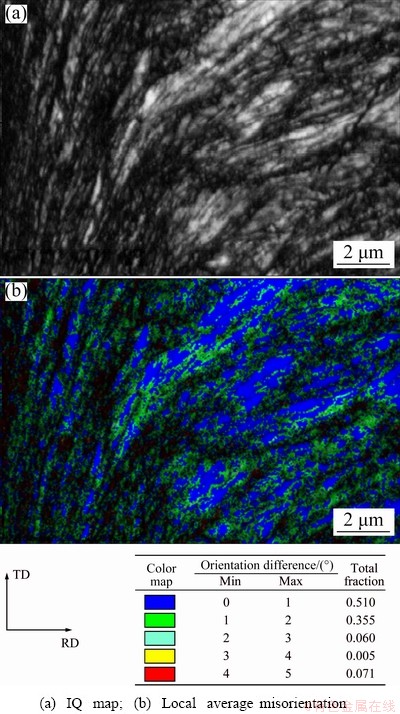
Fig. 4 Orientation map of deformed zone on blanked edges (SPM 600)
The EBSD technology can be used to obtain the microstructures of blanked edges and their surrounding zones to provide abundant information about the evolution of microstructures in the blanking process. Figure 4(a) shows the image quality (IQ) of EBSD patterns in the deformed zone of the blanked edge. According to the scanning information of the orientation mapping of microzones, the quality of Kikuchi lines obtained in the zone was demonstrated using different gray scales. However, the distortion and deformation of the crystals within the diffraction zone due to the effect of residual strain decrease the quality of EBSD patterns so that the IQ map is able to qualitatively reflect the distribution conditions of strains within the microstructures [16]. Plastic deformation leads to the occurrence of a large number of dislocations in metal grains, whilst lattice distortion around the dislocation accumulates with the growth of dislocations. During the violent deformation, small-angle orientation changes appear in the local zones of materials to form various substructures including dislocation walls, microzones and even sub-grains. The orientation change of local zones within metal grains under large deformation reflects the accumulation of the dislocations [17,18]. The local average misorientation (Fig. 4(b)) attained based on the EBSD technology is sensitive to the subtle change of orientation in grains, which can qualitatively measure the relative dislocation density of deformed metals [19]. It can be seen that a large number of geometrically necessary boundaries (GNBs) and incidental dislocation boundaries (IDBs) are formed in the deformed zone of the blanked edges during the blanking. The grains in the zone are subjected to violent plastic deformation and stretched along the blanking direction to form strip-shaped microstructures, with a large misorientation of grains. In this case, a fragmentation layer of grains is formed. However, many high-angle GNBs for coordinating different strain zones have evolved into grain boundaries, and occupied a major proportion of the near shear zone. With the proceeding of blanking, grains are rotated so that the orientations of some grains are gradually consistent to form a special preferred orientation.
The misorientation and size of grains in the blanked edges at a high punching speed are shown in Fig. 5. It can be seen that the proportion of grains with high-angle orientation greatly increases in the blanked edge, and also fine grains with a small size are mainly found. This indicates that at an ultra-high punching speed, the local zone of the blanked edges presents a relatively low dislocation density (low local average misorientation), where micro-crystals (at the submicron order) are present. Furthermore, a large number of high-angle boundaries (large misorientation) are formed, accompanied with a certain preferred orientation (that is, special texture) of grains.
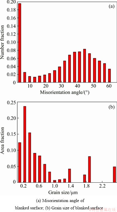
Fig. 5 Misorientation and size of grains in blanked edges at ultra-high punching speed
Using Eulerian angles defined by Bunge, the random crystal orientation was realized by rotating from the initial orientation by φ1, Φ and φ2, which were set in the range of 0°-90°. The characteristic map of Euler orientation based on φ2 at the interval of 5° was selected to establish the orientation distribution function (ODF) for describing the textures of the diffraction microzones. According to the information shown in the pole figure (PF) and inverse pole figure (IPF), the textures of the blanked edges are shown in Fig. 6.
Through analysis using the INCA crystal software, strong {001}<100> cube textures (maximum pole densities of 9 and 12) and secondarily strong  textures (maximum pole densities of 4 and 7) are formed on the blanked edges (SPM 3000) at an ultra-high punching speed. According to the theory of orientation-induced nucleation, grains with the cubic orientation exhibit an advantage in the number of nucleation and grain size relative to grains with the other orientations. In contrast, cube textures are easily affected by various factors including nucleation and high-angle boundary migration, and are formed due to recrystallization annealing [20,21]. Therefore, more {001}<100> cube textures are formed on the blanked edges at an ultra-high punching speed.
3.2 TEM characterization of blanked edges
As described above, to determine the evolution of microstructures in the blanked edges and their surrounding deformed zone, Sample III perpendicular to the blanked edges was prepared by using the preparation method of planar samples and was observed. The TEM microstructures are shown in Fig. 7. It can be seen that the blanked edge and its surrounding deformed zone show very different microstructural characteristics. Grains in the Zone A adjacent to the blanked edges were obviously stretched along the blanking direction under the combined effect of pressures and shear stress to form elongated grains with large deformation. The zone undergoes more significant deformation than the surrounding Zones B, C and D. After grains stretch to form the elongated thick-wall dislocation cells, dislocation of the cell walls increases and becomes entangled to form a dislocation wall. Furthermore, the dislocation wall collapses to form multiple sub-grains with a low misorientation under the effect of heat. With the proceeding of blanking induced deformation, a small equiaxed zone is formed through rotation of sub-grains at the sub-boundary. In the subsequent deformation process, the dislocations climb and unlike dislocations on the sub-boundary, are mutually offset and disappear [22,23]. There are many ultra-fine grains in the Zone A, with a grain size of 50-100 nm. The diffraction patterns of the selected area also show distinct rings, which conform to EBSD characterization results that many high-angle boundaries in the Zone A. Some ultra-fine grains exhibit clear boundaries and low internal dislocation density. Thus, it can be inferred that the grains are typically formed by dynamic recrystallization [24]. It was also found that the diffraction patterns of selected Zones D to A of the samples change from the discrete points to the discontinuous rings. These observations indicate that grains are constantly refined and the misorientation of grains constantly increases with the increase of strain.
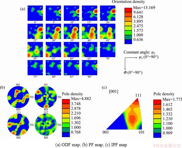
Fig. 6 Textures of deformed zone in blanked edges
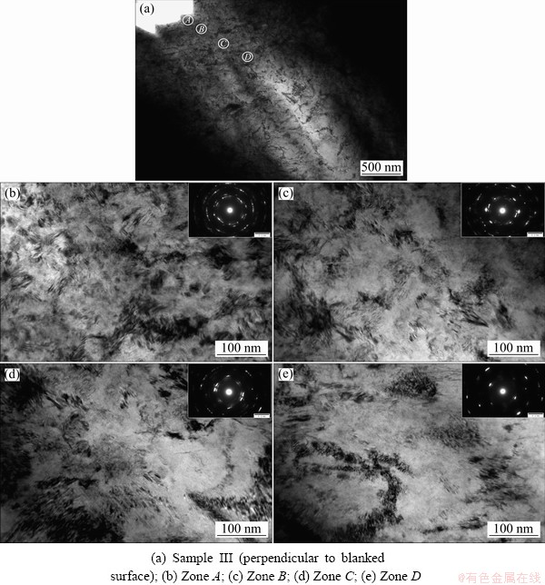
Fig. 7 TEM images of blanked edges and corresponding affected zones
According to the rotational dynamical recrystallization (RDR) of sub-grains proposed by NESTCRCNKO and MEYERS [25], TEM was utilized to observe microstructures of the ultra-high-speed blanked edge. It was found that dislocation cells and tangles on the blanked edges constantly absorb dislocations under combined effects of large strain, plastic deformation at a high strain rate and temperature rise to transform into sub-grains and grains. On this condition, sub- boundaries are generated which form high-angle grain boundaries through short-distance movement. Moreover, sub-grains are stretched, broken and rotated under the effects of ultra-high strain, thus further from nano-crystals (Fig. 8(b)).
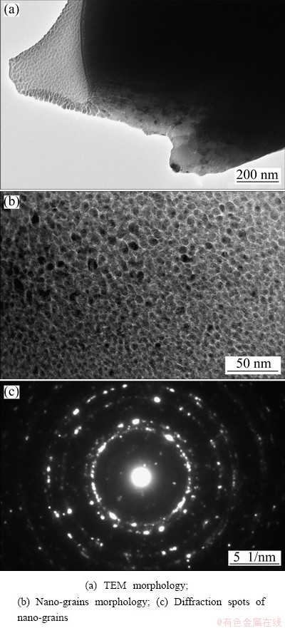
Fig. 8 Microstructures of adjacent area of blanked edges at ultra-high punching speed
From the diffraction patterns in the re-crystallized zone, it can be seen that the diffraction ring is more intact and smoother, and the number of layers of the ring is also more (Fig. 8(c)). The results indicate that there is a large misorientation between grains consisting of high-angle boundaries, instead of sub-boundaries. Additionally, due to the thermal softening effect caused by local high temperature, the local zone is subjected to more violent plastic deformation. In this case, adiabatic shear is likely to occur to form adiabatic shear characterized by dynamic recrystallization [26,27].
To further elucidate the evolution of microstructures in the shear zone on the blanked edges, Sample IV of the shear zone was prepared using the method for preparing cross-section samples. TEM observations of microstructures are displayed in Fig. 9. It can be clearly seen that the grain size of the shear zone (Sample IV) is larger than that of the zone (Sample III) near the shear zone, perpendicular to the direction of the blanked edges. This implies that grains stretch along the blanking direction. It can also be found that a unique type of deformation twins occurred in the shear zone in the blanked edges. C5191 phosphor bronze belongs to a face-centered cubic system, which has many slip systems and the deformation was mainly in the form of slip. However, the blanked edge was instantaneously subjected to a large shear stress during ultra-high-speed blanking. Under these conditions, the dislocation density significantly increased. Dislocations are entangled and piled to form a dislocation wall, thus delaying the initiation of the slip system. In this case, the occurrence of twins can compensate for the deficiency of the number of slip systems to satisfy the demand of great deformation [28,29]. The twin boundaries in the figure are not straight but bend to some extent, which implies that lattice distortion is generated around the twin boundary. Moreover, a certain polygonization process occurs in and around the twins [30,31]. With increasing blanking speed, more dislocation motions occur in the grains. The dislocation motion is hindered by the grain boundary to cause the piling up of a large number of dislocations in the vicinity of the grain boundary, thus forming new sub-grains. The newly generated sub-grains will then evolve into the structures with a high-angle grain boundary when the blanking speed is further increased.
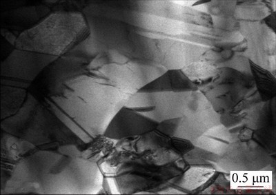
Fig. 9 Microstructures of shear zone
The dislocations are gradually entangled and converged to form the dislocation cell in the blanking process. As the blanking-induced deformation continues to grow, the dislocation cells grow in quantity whilst decreasing in size. Furthermore, the dislocation density of the cell wall further increases with the cell wall constantly moving to the grain boundary. Eventually, the dislocation tangles in the cell wall constantly converge resulting in the collapse of the dislocation cells, thus forming low-angle grain boundaries. A large number of sub-micro-scale unstable sub-grains are found in grains and small-angle textures rotate under the extrusion effects induced by blanking of deformation. Furthermore, twins and sub-grains are broken, extruded and kinked, so numerous crystal defects are entangled and converged to generate high distortion energy. Additionally, the sub-grains are gradually coarsened under the temperature-rise effect to form sub-grains with apparent and high-angle boundaries. The sub-grains continue to grow as a crystal nucleus for recrystallization and finally grains are coarsened to have significantly larger sizes than that of grains in the zone of Sample III.
4 Conclusions
(1) Grains in the edges of C5191 phosphor bronze sheets subjected to ultra-high-speed blanking undergo significant plastic deformation, which are stretched along the blanking direction to form strip-shaped microstructures. The misorientation of grains increases and the fragmentation layer of grains is formed. As the blanking process proceeds, grains are rotated, and so the orientations of some grains are gradually consistent to form a special {001}<100> cube texture.
(2) Diffraction patterns in the zones adjacent to the blanked edges with different distances change from discrete points to discontinuous rings, showing different microstructural characteristics. There are many ultra-fine grains with the size of 50-100 nm in the Zone A adjacent to the blanked edges. In the zone, diffraction patterns appear as distinct rings, with clear grain boundaries and low internal dislocation density, indicating that they are typical grains formed by dynamic recrystallization.
(3) Deformation twins are found in the shear zone of the blanked edges and are rotated and coarsened under the blanking-induced extrusion effect and local temperature-rise effect, which further form sub-grains with clear and high-angle boundaries.
(4) During ultra-high-speed blanking, the local zone of the blanked edges is subjected to adiabatic shear due to high-speed deformation and adiabatic temperature rise, accompanied with dynamic recrystallization. This result suggests a new mechanism which largely differs from the common blanking mechanism.
Acknowledgments
The authors are grateful for the financial supports from Jiangsu Key Laboratory of Precision and Micro-manufacturing Technology of China (JSJMYWX2020-01), Zhejiang Provincial Natural Science Foundation of China (LY18E050005) and the Startup Foundation for Introducing Talent of Nanjing Institute of Industry Technology (YK18-13-02) of China.
References
[1] SUBRAMONIAN S. Improvement of punch and die life and part quality in blanking of miniature parts [D]. Columbus: The Ohio State University, USA, 2013: 1-6.
[2] GULCIMEN B C, SOYARSLAN C, BARGMANN S, HAHNER P. Experimental and computational study of ductile fracture in small punch tests [J]. Materials, 2017, 10: 1185-1204.
[3] MORIN D, HOPPERSTAD O S, BENALLAL A. On the description of ductile fracture in metals by the strain localization theory [J]. International Journal of Fracture, 2018, 209: 1-25.
[4] MUCHA J. An experimental analysis of effects of various material tool’s wear on burr during generator sheets blanking [J]. International Journal of Advanced Manufacture Technology, 2010, 50: 495-507.
[5] ACHOURI M, GILDEMYN E, GERMAIN G, SANTO P D, POTIRON A. Influence of the edge rounding process on the behaviour of blanked parts: Numerical predictions with experimental correlation [J]. International Journal of Advanced Manufacture Technology, 2014, 71: 1019-1032.
[6] ISMAIL A B, RACHIK M, MAZERAN P E, FAFARD M, HUG E. Material characterization of blanked parts in the vicinity of the cut edge using nanoindentation technique and inverse analysis [J]. International Journal of Mechanical Sciences, 2009, 51: 899-906.
[7] GAUDILLIERE C, RANC N, LARUE A, MAILLARD A, LORONG P. High speed blanking: An experimental method to measure induced cutting forces [J]. Experimental Mechanics, 2013, 53: 1117-1126.
[8] SAPANATHAN T, IBRAHIM R, KHODDAM S, ZAHIRI S H. Shear blanking test of a mechanically bonded aluminum/ copper composite using experimental and numerical methods [J]. Materials Science and Engineering A, 2015, 623: 153-164.
[9] RAFSANJANI A, ABBASION S, FARSHIDIANFAR A, IRANI N. Investigation of the viscous and thermal effects on ductile fracture in sheet metal blanking process [J]. International Journal of Advanced Manufacture Technology, 2009, 45: 459-469.
[10] HU Dao-chun, CHEN Ming-he, OUYANG Jin-dong, YIN Li-ming. Finite element analysis of the thermal effect in high-speed blanking of thick sheet metal [J]. International Journal of Advanced Manufacture Technology, 2015, 80: 1481-1487.
[11] WISNIEWSKI W, RUSSEL C. An experimental viewpoint on the information depth of EBSD [J]. Scanning, 2015, 9: 2921-2924.
[12] CHEN Shao-kai, LI Qing-yu, ZHUANG Miao, XU Fei. EBSD and its application in materials research [J]. Rare Metal Materials and Engineering, 2006, 35: 500-504.
[13] WILKINSON A, BRITTON T, JIANG J, MEADEN G, DINGLEY D. High accuracy EBSD: A review of recent applications, innovations, and remaining challenges [J]. Microscopy Microanalysis, 2011, 17: 402-403.
[14] WRIGHT S I, NOWELL M M, KLOE R D, CAMUS P, RAMPTON T. Electron imaging with an EBSD detector [J]. Ultramicroscopy, 2015, 148: 132-145.
[15] MA Xiu-mei, YOU Li-ping. Simple preparation method for TEM cross-sectional specimens of thin-film materials [J]. Journal of Chinese Electron Microscopy Society, 2015, 34: 359-362. (in Chinese)
[16] HUANG Ya-ming, PAN Chun-xu. Micro-stress-strain analysis in materials based upon EBSD technique: A review [J]. Journal of Chinese Electron Microscopy Society, 2010, 29: 1-11. (in Chinese)
[17] CAO W Q, GODFREY A, LIU Q. Determining dislocation cell sizes for high-strain deformation microstructures using the EBSP technique [J]. Journal of Microscopy, 2003, 211: 219-229.
[18] HUMPHREYS F J, BATE P S, HURLEY P J. Orientation averaging of electron backscattered diffraction data [J]. Journal of Microscopy, 2001, 201: 50-58.
[19] MENG Yang, REN Qun, JU Xin-hua. Evaluation of dislocation density by local grain misorientation in deformed metals [J]. Transactions of Materials and Heat Treatment, 2014, 35: 122-128. (in Chinese)
[20] CHEN Fang-fang. Influence of recrystallization texture on mechanical property of aluminum alloy sheets [D]. Tianjing: Hebei University of Technology, China, 2007: 20-35. (in Chinese)
[21] XU Jin, MAO Wei-min, FENG Hui-ping, SHU Long-wei. Influence of annealing process on cube texture formation in aluminum foil of high voltage anode electrolytic capacitor [J]. The Chinese Journal of Nonferrous Metals, 2001, 11: 42-46. (in Chinese)
[22] ALAWADHI M Y, SABBAGHIANRAD S, WANG Y C, HUANG Y. Characteristics of grain refinement in oxygen-free copper processed by equal-channel angular pressing and dynamic testing [J]. Materials Science and Engineering A, 2020, 775: 1-8.
[23] WANG Song-wei, ZHANG Shi-hong, SONG Hong-wu, CHEN Yan. Evolution of microstructure of TP2 copper tube during drawing process [J]. The Chinese Journal of Nonferrous Metals, 2019, 29(4):782-789. (in Chinese)
[24] TOMCZYK A, SEWERYN A, GRADZKA-DAHLKE M. The effect of dynamic recrystallization on monotonic and cyclic behaviour of Al-Cu-Mg alloy [J]. Materials, 2018, 11: 874-892.
[25] NESTERENKL V F, MEYERS M A, LASALVIA J C, BONDAR M P, CHEN Y J, LUKYANOV Y L. Shear localization and recrystallization in high-strain, high-strain- rate deformation of tantalum [J]. Materials Science and Engineering A, 1997, 229: 23-41.
[26] LI Guo-ai. Deformation behaviors and microstructure change of several metals under high velocity impact conditions [D]. Harbin: Harbin Institute of Technology, China, 2005: 80-84. (in Chinese)
[27] WANG Yan-fei, WANG Ming-sai, YIN Kun, HUANG Ai-hui, LI Yu-sheng, HUANG Cong-xiang. Yielding and fracture behaviors of coarse-grain/ultrafine-grain heterogeneous- structured copper with transitional interface [J]. Transactions of Nonferrous Metals Society of China, 2019, 29(3):588-594.
[28] ZHOU Jun, WANG Zhi-fa, CUI Da-tian, JIANG Guo-sheng. Microstructure of shearing plane and new method for refining grains technology in sheets [J]. The Chinese Journal of Nonferrous Metals, 2008, 18: 266-270. (in Chinese)
[29] ZHANG Xue-hui, LI Xiao-xian, LIU Wei-jiang, YANG Kai, ZHU Sheng-jian, JIANG Miao. Effect of cold deformation on microstructures and properties of Al2O3-dispersion strengthened copper [J]. The Chinese Journal of Nonferrous Metals, 2018, 28(4): 705-711. (in Chinese)
[30] YANG Yang, LIAN Xiao-long, WANG Jun-liang. Effect of the grain boundary character distribution on the self-organization of adiabatic shear bands in 1Cr18Ni9Ti austenitic stainless steel [J]. Journal of Materials Science, 2019, 54: 7256-7270.
[31] RYABOV P N, KUDRYASHOV N A, MURATOV R V. Adiabatic shear bands localization in materials undergoing deformations [J]. Journal of Physics: Conference Series, 2017, 788: 1-4.
胡道春1,2,陈明和2,王 蕾2,3,王红军1
1. 南京工业职业技术大学 工程技术实训中心,南京 210023;
2. 南京航空航天大学 江苏省精密与微细制造技术重点实验室,南京 210016;
3. 南京工业职业技术大学 机械工程学院,南京 210023
摘 要:为了研究C5191磷青铜在超高速冲裁条件下的变形机制,借助DOBBY-OMEGA F1超高速冲床完成0.12 mm厚的C5191磷青铜板材在3000冲次/分条件下的超高速冲裁试验,并分别利用EBSD和TEM技术对冲裁断面进行显微组织表征。结果发现,冲裁断面区域晶粒沿着冲裁方向拉长排列,局部区域形成较强的{001}<100>立方织构(极密度分别为9和12)和次强的织构(极密度分别为4和7);同时,冲裁断面的剪切带区域存在变形孪晶,并在冲裁挤压和局部温升效应下发生旋转、粗化,形成晶界清晰、具有大角度晶界的亚晶;C5191磷青铜薄板在超高速冲裁过程中发生绝热剪切,并伴随有动态再结晶产生。
关键词:C5191磷青铜;超高速冲裁;冲裁断面;绝热剪切;动态再结晶
(Edited by Xiang-qun LI)
Corresponding author: Ming-he CHEN; Tel: +86-25-84892508; E-mail: meemhchen@nuaa.edu.cn
DOI: 10.1016/S1003-6326(21)65530-9
1003-6326/ 2021 The Nonferrous Metals Society of China. Published by Elsevier Ltd & Science Press

