Trans. Nonferrous Met. Soc. China 22(2012) s813-s819
Process analysis of direct laser melting to fabricate layered hybrid beads
Jeong-hwan JANG1, Sung-min MUN1, Tae-hyun KIM1, Young-hoon MOON1
School of Mechanical Engineering, Engineering Research Center for Net Shape and Die Manufacturing, Pusan National University, Busan 609-735, Korea
Received 21 May 2012; accepted 27 September 2012
Abstract: The successful fabrication of layered hybrid beads by DLM process is limited by dissimilar melting ranges of different powders. For the application of DLM process into manufacturing industries, target mechanical properties of final product must be achieved. Process analysis was performed for the DLM fabrication of layered hybrid beads by using stainless steel (SS 316L) and titanium powders. For the analysis of fabrication characteristics, single hybrid bead was formed using SS316L powder onto the base plate and then Ti powder was melted onto the previous melted layer. In addition, multi-layer hybrid beads were fabricated for the analysis of the layering effects between them. From these studies, the effects of the processing parameters, such as laser power, scan rate and scan line spacing on surface morphology were characterized and optimum processing conditions for the DLM fabrication of layered hybrid beads were developed.
Key words: stainless steel 316L; Ti powder; energy density; surface roughness; direct laser melting process; layered hybrid beads
1 Introduction
Rapid prototyping has used to form near-net-shape objects of resin, ceramics, metals and their composites directly from CAD data. Laser melting processes for metal powders also enable the production of complex shapes in a wide variety of materials and at a reduced time [1-3]. Direct laser melting (DLM) is the powder bed process that begins with the deposition of a thin layer of powder onto a substrate.
Austenitic stainless steels are widely used owing to their excellent corrosion resistance, whilst their low hardness leads to poor surface properties in terms of wear and fatigue resistant [4-7]. The room temperature ductility of titanium (Ti) and its alloys is generally less than that of the common structural metals including stainless steels. Ti in contact with itself or other metals exhibits a greater tendency to gall than stainless steel does. Therefore, a great deal of published information exists on Ti forming practices in the common commercial forming processes [8-10].
DLM process, that is basically non-contact die-less process, has the capacity to manufacture hybrid layer with dissimilar metals, particularly if the substrate on which the component is built is one metal and the powder material is the other. Thus, by combining materials in the DLM process it is possible to choose the most suitable properties for specific purposes. For this system of manufacture to be useful, the potential problems with reactions between the dissimilar materials must be overcome. Recent reviews of the DLM process have been described the use of various materials and have been reported when diffusion bonding substrate to Ti [11-14].
The objective of the present study is to study the effect of the processing parameters on surface morphology and optimum processing conditions in obtaining better surface characteristics for the DLM fabrication of layered hybrid beads.
2 Experimental
2.1 Materials and DLM system
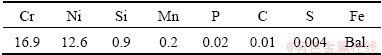
A commercial pure Ti metal powder with a particle size of less than 45 μm and SS 316L metal powder with a particle size of less than 100 μm were used as the starting materials. The chemical composition of SS 316L powder is given in Table 1.
Table 1 Chemical composition of SS316L powder (mass fraction, %)
In this system, an ytterbium fiber laser beam with a nominal diameter of 0.08 mm and a maximum power of 200 W in an argon or nitrogen gas environment was used. In the DLM process, a powder layer was deposited onto the substrate, which was attached to the build cylinder. The laser beam scanned the powder bed, and melted the powder. The melted metal solidified forming a solid substrate region on top of the substrate. The build cylinder was then lowered, and the next layer of powder was deposited. Successive scans and lowering of the cylinder were performed until the desired structure was completed.
2.2 Optimization of process parameters
In order to understand the effects of the process parameters such as laser power, scan rate, overlap on the DLM process, a series of experiments were carried out to analyze the optimal parameters. The component qualities are strongly influenced by the deposited bead dimensions which are mainly controlled by the laser energy input [15,16]. Hence, the effects of the SS316L and Ti deposited layer on SS316L plate substrate by single-line bead formation and single-layer formation of 10 mm×10 mm with different laser processing parameters were studied.
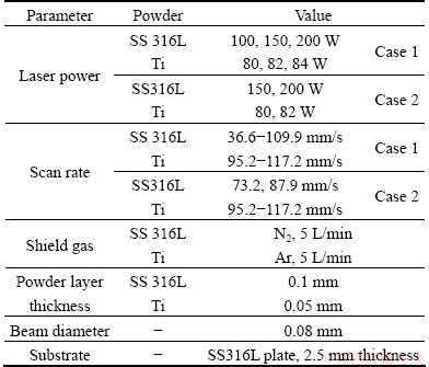
To analyze a DLM single-line bead, SS 316L powder and Ti powder were laser melted each on the SS316L plate using various processing parameters (case 1). For the deposition of two different metal powders, single hybrid line was melted using SS 316L powder onto the same material plate and then Ti powder was melted onto the previous deposited layer (case 2). Table 2 lists the experiment parameters.
Table 2 Parameters for single-line formation
For the analysis of fabrication characteristics, a single hybrid layer was fabricated by laser scan in simple linear direction. Based on the single hybrid layer formation, the multi hybrid layers formation experiment was carried out. The first layer was deposited using SS316L powder onto the same material plate and then Ti powder was melted onto the previous Ti deposited layer. Typical processing parameters are listed in Tables 3 and 4.
Table 3 Parameters for single-layer and formation
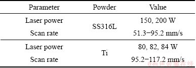
Table 4 Parameters for multi-layer formation

Figure 1 illustrates the surface of the single-layer that was measured for roughness. The sample surface roughness was measured at five different positions perpendicular to the laser scanning direction.
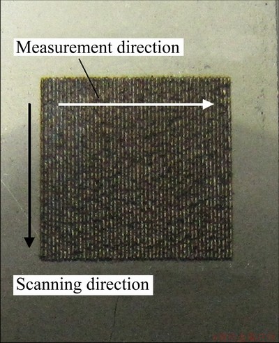
Fig. 1 Surface roughness measurement of deposited layer
To reveal the microstructure of the deposited layers, the fabricated samples were sectioned in the melt direction, polished using the usual metallographic procedure and immersed. A mixed solution of 50% HNO3 and 50% HCl (volume fraction) for the SS316L and mixed solution of 5 mL NH4FHF, 100 mL distilled H2O, and 2 mL HCl for the Ti were used. The mechanical properties of the deposited layers were evaluated by measuring the hardness across the deposited layers cross-section using a micro-hardness tester.
3 Results and discussion
3.1 Characteristics of single-line formation
In order to fabricate defect-free components, it is important to optimize the power, scan rate, and scanning pattern of the laser beam. When the supplied energy density is insufficient to fully melt the powder, unmelted powder remains on the layer and produces defects. The temperature of the powder in the vicinity of the melted zone is low. In contrast, when the supplied energy density is sufficient to melt the powder, the melting zone becomes large and the temperature in the vicinity of the melted zone will remain high. This high temperature assists full melting of the powder in the next layer. Therefore, the density of the specimen depends on the supplied energy density at a constant thickness of powder layer.
The SS316L powder and the Ti powder can be processed over a relatively wide range of processing parameters as shown in Figs. 2 and 3. The laser energy input of the process can be described by the energy density which can be calculated by the simplified equation as
E=P/(dv) (1)
where E is energy density, J/mm2; P is the laser power, W; d is the diameter of the laser beam, mm, and v is the scan rate, mm/s.

Fig. 2 Effects of energy density on deposited width for Ti powder (a) and SS316L powder (b)

Fig. 3 Effects of energy density on depth/height ratio for Ti powder (a) and SS316L powder (b)
At higher energy density, the molten area can be maintained for a longer time in its liquid state and more heat is transferred to powder particles. Notice that owing to the good absorption of the laser energy, the deposited width can attain very high values at high laser power and low scan rate. At low energy density, the effect of the deposited layer onto the substrate is very weak. When the induced energy is small, corresponding to a low laser power at high scan rate, the melted lines become narrower. It will decrease the bonding strength between the deposited layer and substrate because the molten pool energy is insufficient to re-melt enough existing material.
According to Fig. 3, the depth/height ratio of the deposited layer decreased with the increase of the energy density. It should be pointed out that the ratio of depth to height is an important criterion to estimate whether the energy density is appropriate for the process or not. If the ratio is too large, too much powder from the previous layers can be remelted during subsequent laser scanning, causing irregularities in the deposited shape and the excessively penetrates within the substrate. On the other hand, too small a ratio is scarcely bonded to substrate material because the molten pool energy is insufficient to re-melt enough existing material [15-18]. The subsequent single-layer formation experiment will determine the suitable range of energy density as listed in Table 3.
Optical analysis of single-line formation on the substrate showed that titanium and stainless steel 316L behaved very differently as shown in Fig. 4. The SS 316L powder wets the substrate much more readily, spreads across the surface. However, the bead shape of Ti powder is relatively shallower penetrated depth into the substrate compared to the SS 316L powder.
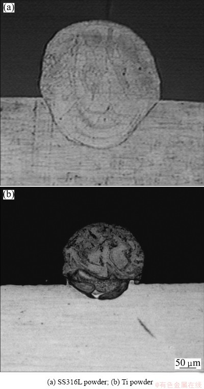
Fig. 4 Cross-sectional bead shapes of single-line formation
Figure 5 shows the cross-sectional bead shapes of single-line formation with Ti melting onto previous SS 316L deposited layer. The single-line bead formation was manufactured using laser power of 200 W, scan rate of 87.9 mm/s for SS 316L melting and then Ti powder is melted onto the previous SS 316L deposited layer using different energy density, 8.53 J/mm2 (laser power of 82 W, scan rate of 102.5 mm/s) and 9.99 J/mm2 (laser power of 80 W, scan rate of 117.2 mm/s), respectively. The first layer of SS 316L strongly wetted the substrate, widening the lines and fusing them together producing a deposited layer with no sign of balling. Crack was seen to occur at the interface between Ti and SS 316L layer at lower energy density, whilst no cracking was seen in the Fig. 5(a). The crack within the interface region was confined to a thin layer at the interface between the previous SS 316L layer and the Ti layer, and did not spread into the remaining layers of the Ti layer or into the previous SS 316L layer. The hardness of the phases near the interface is higher for Ti layer than that of SS 316L layer as shown in Fig. 6. The most likely cause of these cracks is the presence of a hard, brittle intermetallic phase at the interface. Ti powder has a significantly higher melting point than SS 316L powder. Thus the thermal stresses that develop because of the differences in thermal expansion coefficient may lead to hot tearing [11].
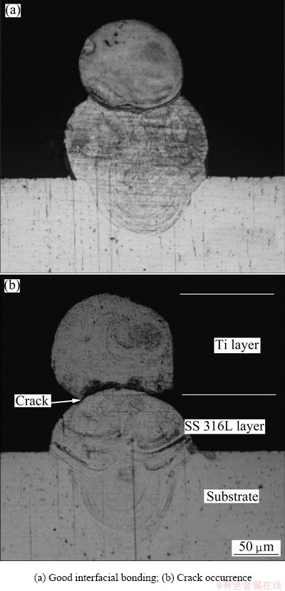
Fig. 5 Cross-sectional bead shapes of single-line formation with Ti melting onto previous SS316L deposited layer
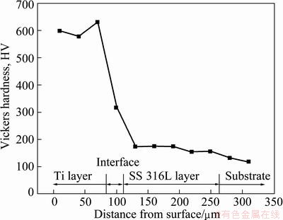
Fig. 6 Micro-hardness profile of laser deposited layer
Figure 6 shows the micro-hardness profile of laser deposited layer. The hardness of Ti layer was about HV600. The hardness dropped rapidly at the interface and SS 316L layer to the values of about HV300 and HV170 , respectively.
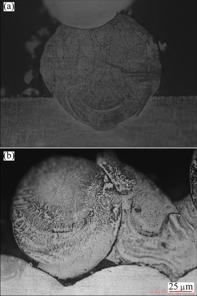
Fig. 7 Microstructures of SS 316L powder (a) and Ti powder (b) after DLM process
Figure 7 shows the microstructures after the DLM process. As shown in Fig. 7(a), the microstructure is composed of large grain size. All the grains are separated by straight boundaries. The typical rapid solidified epitaxial dendrites of different lengths are formed preferentially into the substrate in most deposited area. In case of Ti deposited microstructure, the acicular crystal grain is observed.
3.2 Characteristics of single-layer and multi-layer formation
The morphological photographs of Ti single layer on the substrate at various scan line spacings are shown in Fig. 8. The scan line spacing must be smaller than the single-line width to ensure good metallic bonding between neighboring lines and minimum porosity. Since the width of a line is not only determined by the laser beam size but also by the laser energy density, scan rate and powder property, scan line spacing cannot be simply defined by the laser beam size. Single layers were produced with laser power of 82 W and scan rate of 102.5 mm/s. At a scan line spacing of 0.08 mm, the balling and rough surface is appeared. In contrast, a non-continuous porous depositing is revealed as shown in Fig. 8(c). At the single-line formation, the deposited width using laser power of 82 W and scan rate of 102.5 mm/s is about 0.09 mm as shown in Fig. 2(a). When the scan line spacing is smaller than the deposited width, the metallic bonding between neighboring lines cannot combine, whilst too large scan line spacing leads to balling and rougher surface. Thus, scan line spacing of 0.1 mm was chose for single-layer formation with Ti powder.

Fig. 8 Single layer of Ti powder on SS316L plate at various scan line spacings
Figure 9 shows the surface roughness of the single-layer formation at various process parameter values. The surface roughness was measured at five positions, and the mean value was taken as representative of the sample. In case of the SS 316L single-layer formation, the deposited layer between 80.6 and 95.2 mm/s with 200 W laser powers appears lower surface roughness than other ranges of the scan rate. Thus, parameter settings with laser power of 200 W and scan rate of 80.6-95.2 mm/s have been chosen for multi-layer formation. In case of the Ti single-layer formation, the deposited layer of 82 W laser power is the smoother than that of other laser powers. At the laser powers of 80 W, the layer with of 109.9 and scan rates of 117.2 mm/s are the lowest. Thus, parameter settings of multi-layer formation have been chosen as the follows. The first layer with SS 316L powder is using 200 W laser power and 80.6-95.2 mm/s scan rates, and second layer with Ti powder is using 82 W laser power and 109.9 and 117.2 mm/s scan rates.
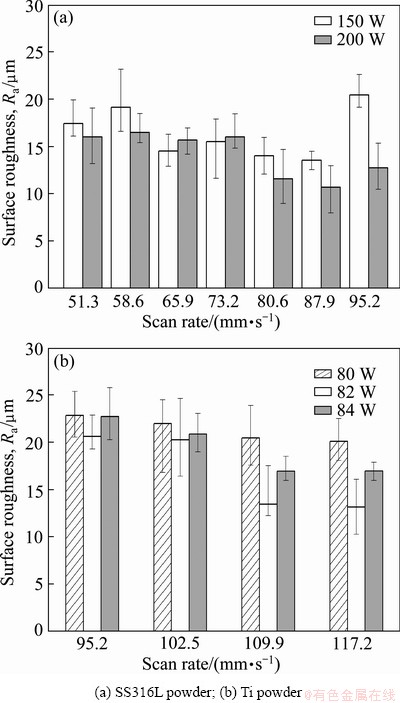
Fig. 9 Surface roughness for single-layer formation
Figure 10 shows the surface roughness for multi-layer formation with different powders. In case of specimens 1 and 2, the surface roughnesses are higher than that of the other specimens due to the rougher surface of first layer. When the first layer is smoother, the surface of multi-layer is smoother. Figure 11 shows a very strong metallurgical bonding without crack occurrence between the two different metal powders when the Ti powder is deposited with laser power of 82W and scan rate of 109.9 mm/s onto the previous SS 316L deposited layer with laser power of 200W and scan rate of 87.9 mm/s.

Fig. 10 Surface roughness for multi-layer formation

Fig. 11 Cross-sectional view of Ti layer onto previous SS 316L layer
4 Conclusions
1) The energy density is the most important factor that controls the component qualities. A suitable energy density can control the size of the molten pool efficiently to get a good bonding strength between powders and substrate. The ratio of penetrated depth to deposited height can be used for the criterion to estimate whether the laser energy density is suitable or not.
2) There is an appropriate range for the energy density that can fabricate layered hybrid beads stably with a smoother surface.
3) A good interfacial bonding is observed between the Ti deposited layer and the previous SS 316L deposited layer when the Ti powder is deposited with laser power of 82 W and scan rate of 109.9 mm/s onto the previous SS 316L deposited layer with laser power of 200 W and scan rate of 87.9 mm/s.
References
[1] MORGAN R, SUTCLIFFE C J, O’NEILL W. Density analysis of direct metal laser re-melted 316L stainless steel cubic primitives [J]. Journal of Materials Science, 2004, 39(4): 1195-1205.
[2] GUSAROV A V, SMUROV I. Two-dimensional numerical modeling of radiation transfer in powder beds at selective laser melting [J]. Applied Surface Science, 2009, 255(6): 5595-5599.
[3] JOO B D, JANG J H, LEE J H, SON Y M, MOON Y H. Selective laser melting of Fe-Ni-Cr layer on AISI H13 tool steel [J]. Transactions of Nonferrous Metals Society of China, 2009, 19(4): 921-924.
[4] TASSIN C, LAROUDIE F, PONS M, LELAIT L. Improvement of the wear resistance of 316L stainless steel by laser surface alloying [J]. Surface and Coatings Technology, 1996, 80(1-2): 207-210.
[5] CHENG F T, LO K H, MAN H C. A preliminary study of laser cladding of AISI 316 stainless steel using preplaced NiTi wire [J]. Materials Science and Engineering A, 2004, 380(1-2): 20-29.
[6] SHIN H W, LEE H J, YOO H G, LIM K S, LEE M K. Laser-direct patterning of nanostructured metal thin films [J]. The Korean Journal of Metals and Materials, 2010, 48(2): 163-168.
[7] LEE J B, KIM D C, NAM D G, KANG N H, KIM S K, YU J H, RHYM Y M, PARK Y D. Assessment of resistance spot weldability of dissimilar joints of austenitic stainless steels/IF steels and ferritic stainless steels/IF steels [J]. The Korean Journal of Metals and Materials, 2011, 49(1): 64-72.
[8] HOLLANDER D A, WALTER M V, WIRTZ T, SELLEI R, ROHLFING B S, PAAR O, ERLI H J. Structural, mechanical and in vitro characterization of individually structured Ti-6Al-4V produced by direct laser forming [J]. Biomaterials, 2006, 27(7): 955-963.
[9] STAMP R, FOX P, O’NEILL W, JONES E, SUTCLIFFE C. The development of a scanning strategy for the manufacture of porous biomaterials by selective laser melting [J]. Journal of Materials Science: Materials in Medicine, 2009, 20(9): 1839-1848.
[10] WOO K D, KANG D S, MOON M S, KIM S H, LIU Z, OMRAN A N. Evaluation of surface macrostructure and mechanical properties of porous surface Ti-HA biomaterial fabricated by a leaching process [J]. The Korean Journal of Metals and Materials, 2010, 48(4): 369-375.
[11] FOX P, POGSON S, SUTCLIFFE C J, JONES E. Interface interactions between porous titanium tantalum coatings, produced by selective laser melting, on a cobalt-chromium alloy [J]. Surface & Coatings Technology, 2008, 202(20): 5001-5007.
[12] VISWANATHAN A, SASTIKUMAR D, RAJARAJAN P, KUMAR H, NATH A K. Laser irradiation of AISI316L stainless steel coated with Si3N4 and Ti [J]. Optics & Laser Technology, 2007, 39(8): 1504-1513.
[13] HORII T, KIRIHARA S, MIYAMOTO Y. Freeform fabrication of Ti-Al alloys by 3D micro-welding [J]. Intermetallics, 2008, 16(11-12): 1245-1249.
[14] PATTANAYAK D K, FUKUDA A, MASUSHITA T, TAKEMOTO M, FUJUBAYASHI S, SASAKI K, NISHIDA N, NAKAMURA T, KOKUBO T. Bioactive Ti metal analogous to human cancellous bone-fabrication by selective laser melting and chemical treatments [J]. Acta Biomaterialia, 2011, 7(3): 1398-1406.
[15] BEUTH J, KLINGBEIL N. The role of process variables in laser-based direct metal solid freeform fabrication [J]. JOM, 2001, 53(9): 36-39.
[16] LI P, YANG T, LI S, LIU D, HU Q, XIONG W, ZENG X. Direct laser fabrication of nickel alloy samples [J]. International Journal of Machine Tools & Manufacture, 2005, 45(11): 1288-1294.
[17] CAPELLO E, PREVITALI B. The influence of operator skills, process parameters and materials on clad shape in repair using laser cladding by wire [J]. Journal of Materials Processing Technology, 2006, 174(1-3): 223-232.
[18] JANG J H, JOO B D, MUN S M, SUNG M Y, MOON Y H. Application of direct laser melting to restore damaged steel dies [J]. Metals and Materials International, 2011, 17(1): 167-174.
(Edited by LONG Huai-zhong)
Foundation item: Project (2012-0000-965) supported by the National Core Research Center Program through the National Research Foundation of Korea Funded by the Ministry of Education, Science and Technology
Corresponding author: Young-hoon MOON; Tel: +82-51-5101672; E-mail: yhmoon@pusan.cu.kr
DOI: 10.1016/S1003-6326(12)61809-3

