J. Cent. South Univ. Technol. (2009) 16: 0614-0620
DOI: 10.1007/s11771-009-0102-7

Finite element analysis on nut post structure of Three Gorges Project ship lift
SHI Duan-wei(ʯ��ΰ), CAI Dong-cai(�̶���), WU Zhi-chun(��־��)
(School of Power and Mechanical Engineering, Wuhan University, Wuhan 430072, China)
Abstract: A nonlinear finite element model of the nut post reinforced concrete (RC) structure of the safety mechanism in the Three Gorges Project (TGP) ship lift was built by ANSYS software. Some irregular structures such as the nut post and the rotary rod were divided by curved surface into a series of regular parts, and the structures were all meshed to hexahedron. Constraint equations were defined between two interfaces with different element sizes and mesh patterns. PRETS179 elements were used to simulate the preload in the tendons and the pre-stressed screws, and the loss of prestressing force was calculated. Five extreme load cases were analyzed. The stress of each part in the structure was obtained. The results indicate that the maximum compressive stress of concrete C35 is 24.13 MPa, so the concrete may be partially crushed; the maximum tensile stress of the grouting motar is 6.73 MPa, so the grouting motar may partially fracture; the maximum von Mises stress of the rotary rod is 648.70 MPa, therefore the rotary rod may partially yield.
Key words: ship lift; safety mechanism; nut post; reinforced concrete structure; finite element analysis
1 Introduction
Though the design of the safety mechanism in the Three Gorges Project (TGP) ship lift has profited from the successful experience of the Niederfinow ship lift (built in 1934, lift height is 37.21 m, ship tonnage is 1 000 t) and the L��neburg ship lift (built in 1975, lift height is 38 m, ship tonnage is 1 350 t) [1], it is necessary to analyze the nut post reinforced concrete (RC) structure of the safety mechanism in the TGP ship lift with finite element analysis (FEA) method, because the scale of the TGP ship lift is larger and the work situation is more complicated (lift height is 113 m, ship tonnage is 3 000 t), some technical criteria are applied for the first time, and many crucial parameters to the structure design are not stipulated in existing design criteria.
SHI et al [2], GAO [3] and CHEN [4] applied FEA to the gear-rack driven mechanism and the nut post safety mechanism of the Xiangjiaba ship lift. But the computational model did not include the RC structure linked to the nut post. FU and FANG [5] carried out stress analysis on the concrete and the tendon of the safety mechanism in the TGP using ALGOR software. JIN et al [6] constructed a finite element model of the TGP ship lift system and carried out modal analysis and dynamic response analysis by ANSYS software.
In this work, a finite element model was simulated by ANSYS software based on the latest design report of the TGP ship lift to predict the stress of each part during extreme load cases.
2 Finite element model of nut post structure
2.1 Nut post structure of safety mechanism
The safety mechanism in the TGP ship lift consists of four nut post mechanisms. The nut post is a columnar structure, slit longitudinally, hollow inside and with an internal screw thread. All nut posts are arranged continuously on the concrete structure. The rotary rod, which moves and revolves about its own axis, is located inside the nut post.
The nut post RC structure consists of the nut posts (the shoved cams are welded at the back), the pre-stressed screws with a strength category of 10.9 (M30, L=505 mm), the tendons (36WS, L=2 430 mm), the grouting mortar (V1/50 by PAGEL), the embedded steel structure (including I-shaped steel girder), the shoved cams welded on the steel girder, the NELSON-headed studs, the 1st stage concrete, the 2nd stage concrete and the reinforcements [7] (Fig.1).
2.2 Finite element model
The finite element model of the nut post RC structure of the safety mechanism is established by ANSYS software. The model consists of one section of the nut post (L=4 950 mm), two sections of concrete of the tower (L=9 900 mm), and half part of the rotary rod that is at the bottom of the nut post (Fig.2).
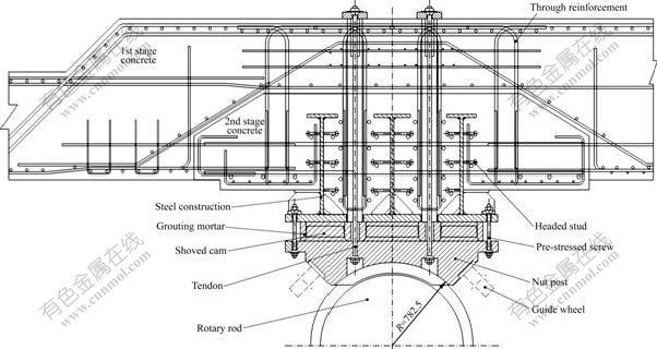
Fig.1 Top view of nut post RC structure of safety mechanism
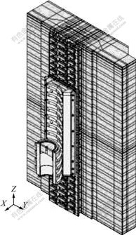
Fig.2 Finite element model of nut post RC structure of safety mechanism
The element number of the model adds up to 414 209, which contains 202 543 SOLID45 elements, 189 756 SOLID65 elements, 21 526 LINK8 elements and 384 PRETS179 elements.
2.2.1 Model of steel
The material of the rotary rod is 42CrMo4V (quenched and tempered) and that of the nut post is GS-25 CrNiMo4 (quenched and tempered), both of their yield strengths are 500 MPa. The material of the steel structure is Q235 with a yield strength of 235 MPa. The material of the tendons is S23J263 (EN 10027-1) with a yield strength of 1 080 MPa. The pre-stressed screw is HV-screw M30 with a strength category of 10.9, whose yield strength is 1 000 MPa. The material of the reinforcement under the water level of 84 m is HRB400 with a yield strength of 400 MPa, and that above the water level of 84 m is HRB335 with a yield strength of 335 MPa. The material of the headed studs is S235 J2 G3+C450 (strength limit fuk��450 MPa and yield strength fyk��350 MPa). The elastic modulus of all steel is 206 GPa, and the Poisson ratio is 0.3.
SOLID45 element was used to model the rotary rod, the nut post, the I-shaped steel girder, the tendons and the pre-stressed screws. The headed studs (welded on I-shaped steel girder) bearing shear force and bending moment were modeled by BEAM188 element. The reinforcements were modeled by LINK8 element. PRETS179 elements were built at the middle of effective length of the pre-stressed screws and tendons.
2.2.2 Model of concrete C30/35
From the bottom to the height of 84 m, the material of the 1st and 2nd stage concrete is concrete C35, and that from the height of 84 m to the top is concrete C30.
According to the concrete structure design criterion GB50010��2002, the elastic moduli of concrete C35 and C30 are 31.5 and 30.0 GPa, respectively. Both of their Poisson ratios are 0.167.
The standard axial compressive and tensile strengths of concrete C30 are fck=20.1 MPa and ftk= 2.01 MPa, respectively. The designed axial compressive and tensile strength are fc=14.3 MPa and ft=1.43 MPa, respectively. The standard axial compressive and tensile strengths of concrete C35 are fck=23.4 MPa and ftk= 2.2 MPa, respectively. The designed axial compressive and tensile strengths are fc=16.7 MPa and ft=1.57 MPa, respectively.
SOLID65 element was used to model the concrete. The constitutive relationship of concrete C30/35 is [8]
 (1)
(1)
where ��c is the compressive stress of the concrete and ��c is the corresponding compressive strain; fc is the design value of axial concrete compressive strength; ��0 is the compressive strain of the concrete when its compressive stress just reaches fc, and when the calculated ��0 is lower than 0.002 0, it is assigned to 0.002 0; ��cu is the ultimate compressive strain of the concrete, if the calculated ��cu is more than 0.003 3, it is assigned to 0.003 3, and when the concrete is compressed axially, it is assigned to ��0; n is a coefficient assigned to 2.0.
One-dimensional link element and bond zone element could be used to simulate the interaction between the concrete and the reinforcement [9-10]. But bond-slip effect was not considered in the non-linear analysis of complex large structures [11-14]. The reinforcement and the concrete of the model are also in perfect bond condition in this work. The interface between the 1st and 2nd stage concrete is not taken into account.
In addition, to ensure convergence and stability of the calculation, descending branch does not appear in the stress��strain curve of concrete C30/35. The concrete model was meshed by SOLID65 elements that are all hexahedron and the element edge length is 20 mm at least.
The shear transfer coefficient for an open crack of the concrete is 0.45, and that for a closed crack is 0.9. The uniaxial crushing stress is assigned to -1 to remove the crushing capability.
2.2.3 Model of grouting mortar
The compressive strength (after 90 d) of the grouting mortar is fck=110 MPa, flexural strength (after 90 d) is ftk=10 MPa. Take the safety factor into account, fc= fck/��c=110/1.5=73.3 MPa, ft=ftk/��t=10/1.8=5.56 MPa. The elastic modulus of the grouting mortar is 39.3 GPa (after 90 d), and the Poisson ratio is 0.167. The constitutive relationship for grouting motar V1/50 is still Formula (1).
2.2.4 Finite element mesh
The nut post, which has some irregular parts such as the thread teeth, the tendon holes and the pre-stressed screws holes, was divided into a series of regular parts by curved surface or work plane. Then, the volume mesh was generated by sweeping, and the hexahedral mesh with high quality was created.
Owing to the complexity of the structure, the model would be huge, consequently difficult to be solved if the connection of mesh nodes of each part needs to be ensured. To reduce the scale of the whole model, two kinds of constraint equation were defined in the model [15].
(1) The constraint equations connecting adjacent regions were defined between two parts where the element size was different, such as the I-shaped steel girder and the concrete, and the grouting motar; the nut post and the grouting motar; the nut at the end of the tendon and the concrete; the nut at the end of the tendon and the nut post; the pre-stressed screws and the I-shaped steel girder, and the nut post. The constraint equations were also defined at the mating teeth of the nut post and the rotary rod.
(2) The constraint equations were defined to connect SOLID45 elements of the I-shaped steel girder and BEAM188 elements of the headed studs.
2.3 Calculating load
2.3.1 Calculating load of nut post
When accident of the chamber happens, all the water in the chamber will be leaked out, and the chamber will float in the chamber pool, and the load will reaches the maximum, which is treated as the design load of the safety mechanism. In such circumstances, the imbalance force due to the leak of water and float force is P= 123 000 kN.
(1) Force induced by thread pitch angle and flank angle of screw
The safety factor is 1.08 [7], 
 . The flank angle of screw is
��=20?, and the thread pitch angle is ��=5.64?, the factors for the horizontal loads are ��X1=cos ��?sin ��=0.321, ��Y1= cos ��?sin ��=0.098. The horizontal loads are FXk1=FZk��X1= 5 330.2 kN, FYk1=FZk��Y1=1 627.3 kN.
(2) Force acting through inclined hinged column
The length of the hinged column is L1=6 400 mm, the maximum displacement of the hinged column is ��XY=212 mm, so the horizontal force coefficient is ��X2=
��Y2= =0.033. Then the force on the rotary rod in
directions X and Y are FXk2=FZk��X2=547.97 kN, FYk2= FZk��Y2=547.97 kN.
Therefore, FX=FXk1+FXk2=5 878.17 kN, FY=FYk1+ FYk2=2 175.27 kN and FZ=FZk=16 605 kN.
2.3.2 Preload in tendons and pre-stressed screws
The nut post was connected to the steel structure by the grouting motar in the vertical direction, while it was connected with the grouting motar, the steel structure, the 1st and the 2nd stage concrete by the pre-stressed tendons in the horizontal direction.
The preload in the tendons and the pre-stressed screws was simulated by using PRETS179 elements. The results show that the stress concentration will be produced if BEAM188 elements are used to simulate the preloading component, while satisfied results can be obtained when SOLID45 elements are used to simulate the preloading component.
The initial preload imposed on the tendons is 900 kN, and the initial preload imposed on pre-stressed screws is 80-290 kN varying with the location [7]. The preload of the tendons will gradually decrease with the progress of time. So, it is necessary to take the loss of prestressing force of the tendons into account [7, 16-17]. There are four main reasons for the loss [18-19]: anchorage slip of the tendons, concrete shrinkage, concrete creep and steel material relaxation caused by air humidity. The calculations are as follows [7].
The elastic modulus of the tendons is E=206 GPa. The diameter is d=36 mm. The cross-sectional area is A=1.018��10-3m2. The length is l=2.3 m, and the effective length is lc=1.8 m.
(1) Anchorage slip of tendons
Anchorage slip of the tendons due to prestress is
?l1=1 mm. From  , the loss of prestressing
force due to anchorage slip of the tendons is
 (2)
(2)
(2) Concrete shrinkage
The sum of concrete shrinkage of the 1st and 2nd stage concrete is  =-0.035%, and the slip of the tendons due to the concrete shrinkage is
  = 0.63 mm, so the loss of prestressing force due to the concrete shrinkage is
 (3)
(3)
(3) Concrete creep
According to DIN 1045-1, the creep rate of the concrete with air humidity of 76.1% is 
 , where creep coefficient of the concrete (h0=50 cm, t0=20 d) is
 ,
,  . The
. The
elastic modulus of concrete C30 is Ecm=30 GPa, so Ec0=1.1Ecm=33 GPa. Therefore, the preload of the tendons is PV=P0-?PV1=900.0-90.7=809.3 kN.
The anchor plate was contacted to the tendons and concrete. When the anchor plate is acted upon by force, the affected region will expand with an angle of 30?, the height of the affected region is h=0.467 m, the width is b=0.637 m, and the area is  =hb=0.297 m2. So ��c=
 = 2.72 MPa, and the creep rate of concrete is
  .
.
Therefore, the loss of prestressing force due to concrete creep is
 (4)
(4)
(4) Steel relaxation
It is known that the preload imposed on the tendons is PV=809.3 kN. When PV is 70%-80% of the ultimate tensile force of the tendon material, the relaxation rate of steel is 3%, and the loss of prestressing force is caculated by 70% relaxation of the ultimate tensile force. So the loss of prestressing force due to the relaxation of steel is
 (5)
(5)
So, the loss of prestressing force of the tendons is
 (6)
(6)
Therefore, after 100 years (the designed life-span), the prestressing force of the tendons is at least Pd=P0-?PV=700 kN.
2.4 Boundary conditions
All the freedom degrees of the top and bottom surface of the model were constrained. The displacements of two sides of the model were also constrained in Y direction, and symmetry constraints were generated on symmetric plane of the rotary rod.
If the load or constraint is directly applied to the nodes of the concrete elements, it will likely lead to stress concentration. The concrete elements near the nodes on which load or constraint is applied will wreck abruptly, which will fail to solve the problem consequently. So flexible pillows are added to the regions where constraint or load is used to avoid stress concentration.
2.5 Load cases
When accident happens, not all of the four mating teeth of the rotary rod may transfer the load with the nut post. So, two situations are considered, respectively: only one mating tooth transferring the load, two mating teeth transferring the load with the nut post.
There are five calculating load cases. Load case 1: only one mating tooth transfers the load, no loss of prestressing force is considered, and the concrete is C35; load case 2: two mating teeth transfer the load, no loss of prestressing force is considered, and the concrete is C35; load case 3: only one mating tooth transfers the load, no loss of prestressing force is considered, and the concrete is C30; load case 4: two mating teeth transfer the load, no loss of prestressing force is considered, the concrete is C30; load case 5: two mating teeth transfer the load, loss of prestressing force is considered, and the concrete is C35.
To verify the contact stress between the nut post and the rotary rod, a model just containing one section of the nut post and half part of the rotary rod was built. The rotary rod was at the bottom of the nut post. A contact pair was defined at the screw thread flanks of the bottom tooth of the nut post and the rotary rod, and friction coefficient was 0.1.
3 Computation and results analysis
3.1 Calculation scheme
The PCG solver was chosen to increase the solving speed for large-scale model. Because of the stress-softening branch in the stress��strain curve of C30 concrete, the infinite norm of displacement was used as a convergence criterion instead of the default L2 norm of force, and the tolerance value was assigned to 0.03-0.05. Choose automatic time stepping, increase the number of substeps, and impose load slowly. Choose augmented Lagrangian method and set KEYOPT (5) of CONTA174 element to close gap. The results are shown in Table 1.
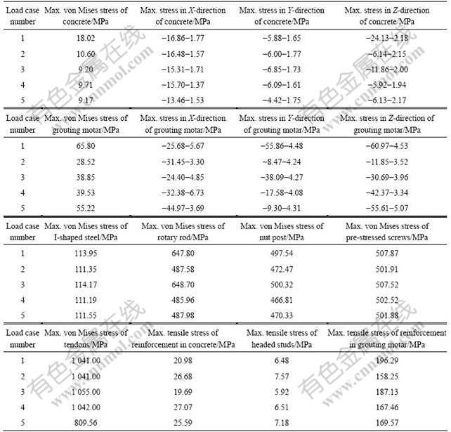
Table 1 Analysis results of five load cases
3.2 Analysis of calculation results
3.2.1 Concrete
The maximum tensile stress of concrete C35 (under the water level of 84 m) is 2.18 MPa (load case 1, in Z-direction), which is lower than the standard axial tensile strength (2.20 MPa). The maximum compressive stress is 24.13 MPa (load case 1, in Z-direction), which is higher than the standard axial compressive strength (23.40 MPa). So the concrete may be partially crushed. The maximum tensile stress of concrete C30 (above the water level of 84 m) is 2.00 MPa (load case 3, in Z-direction), which is lower than the standard axial tensile strength (2.01 MPa). The maximum compressive stress is 15.70 MPa (load case 4, in X-direction), which is lower than the standard axial compressive strength (20.10 MPa).
3.2.2 Grouting motar and reinforcement in grouting motar
The maximum compressive stress of the grouting motar is 60.97 MPa (load case 1, in Z-direction), which is lower than the design value (73.30 MPa). The maximum tensile stress is 6.73 MPa (load case 4, in X-direction), which is lower than the standard value (10.00 MPa), and higher than the design value (5.56 MPa), so the grouting motar may partially fracture. The maximum tensile stress of the reinforcement in the grouting motar is 196.29 MPa (load case 1), which is lower than the tensile strength (350.00 MPa).
3.2.3 I-shaped steel
The maximum von Mises stress of the embedded steel structure is 114.17 MPa (load case 3), which is lower than the yield strength (235.00 MPa).
3.2.4 Rotary rod and nut post
The maximum von Mises stress of the rotary rod is 648.70 MPa (load case 3), which is higher than the yield strength (500.00 MPa), so the rotary rod may partially yield. The maximum von Mises stress of the nut post is 500.32 MPa (load case 3), which is slightly more than the yield strength (500.00 MPa).
3.2.5 Pre-stressed screws and tendons
The maximum von Mises stress of the pre-stressed screws is 507.87 MPa (load case 1), which is lower than the yield strength (1 000.00 MPa). The maximum von Mises stress of tendons is 1 055.00 MPa (load case 3), which is lower than the yield strength (1 080.00 MPa).
3.2.6 Reinforcement in concrete and headed studs
The maximum axial tensile stress of the reinforcement in the concrete is 27.07 MPa (load case 4), which is lower than the tensile strength (350.00 MPa). The maximum tensile stress of the headed studs is 7.57 MPa (load case 2), which is lower than the tensile strength (350.00 MPa).
In addition, when the nut post and the rotary rod contact to each other with the bottom thread tooth, the maximum contact stress between thread flanks of the nut post and the rotary rod is 519.57 MPa, which is lower than the allowable contact stress.
4 Conclusions
(1) Five extreme load cases are analyzed by finite element method.
(2) The maximum compressive stress of the concrete C35 (under water level of 84 m) is 24.13 MPa, so the concrete may be partially crushed; the maximum tensile stress of the grouting motar is 6.73 MPa, so the grouting motar may partially fracture; and the maximum von Mises stress of the rotary rod is 648.70 MPa, therefore, the rotary rod may partially yield.
(3) In the extreme load cases analyzed in this work, accident happens to the ship chamber and only one or two mating teeth of the nut post and rotary rod bear the load. Therefore, the results are conservative. But when the ship lift works, the extreme load cases should be prevented.
References
[1] NIU Xin-qiang. Researches on structrual cruxes of the vertical ship lift in TGP [D]. Wuhan: Huazhong University of Science and Technology, 2005: 2-4. (in Chinese)
[2] SHI Duan-wei, WU Qing-ming, ZHANG Zhi-qiang. Structure analysis of locking mechanism of gear-rack typed ship-lift [J]. Wuhan University Journal of Natural Sciences, 2006, 11(3): 631-636.
[3] GAO Su-he. The finite element analysis for the main components of the driving mechanism and the safety mechanism in the ship box [J]. Heavy Machinery Science and Technology, 2004(4): 1-4. (in Chinese)
[4] CHEN Tao. Virtual prototyping design for ship-lift at Three Gorges Project [D]. Dalian: Dalian University of Technology, 2005: 37-49. (in Chinese)
[5] FU Ni, FANG Yang. The research on the locking mechanism of the ship-lift on the Three Gorges Dam [J]. People��s Yangtze River, 2001, 32(11): 4-5. (in Chinese)
[6] JIN Jing, LIU Yu-biao, CHENG Zai-bin. Dynamic analysis of the three-gorges ship lifting system [J]. Engineering Mechanics, 2007, 24(9): 179-187. (in Chinese)
[7] JOINT VENTURE KuK/LI. Three Gorges Project Ship Lift (Phase D)����Safety mechanism[R]. 2006.
[8] ZHANG Hai-long. Nonlinear finite element analysis method of RC structure limiting bearing capacity [D]. Xi��an: Chang��an University, 2005: 24-29. (in Chinese)
[9] KWAK H G, KIM J H. Numerical models for prestressing tendons in containment structures [J]. Nuclear Engineering and Design, 2006, 236(10): 1061-1080.
[10] OGURA N, BOLANDER J E, ICHINOSE T. Analysis of bond splitting failure of deformed bars within structural concrete [J]. Engineering Structures, 2008, 30(2): 428-435.
[11] BOUAZAOUI L, JURKIEWIEZ B, DELMAS Y, DELMASA Y, LI A. Static behaviour of a full-scale steel-concrete beam with epoxy-bonding [J]. Engineering Structures, 2007, 30(7): 312-321.
[12] HE Xue-jun, ZHOU Chao-yang, LI Yi-hui, XU Ling. Lagged strain of laminates in RC beams strengthened with fiber-reinforced polymer [J]. Journal of Central South University of Technology, 2007, 14(3): 431-435.
[13] KULKARNI S A, LI B, YIP W K. Finite element analysis of precast hybrid-steel concrete connections under cyclic loading [J]. Journal of Constructional Steel Research, 2008, 64(2): 190-201.
[14] NIE J G, QIN K, CAI C S. Seismic behavior of connections composed of CFSSTCs and steel�Cconcrete composite beams: Finite element analysis [J]. Journal of Constructional Steel Research, 2008, 64(10): 680-688.
[15] YE Mei-xin, HUANG Qiong, WU Qin-qin. Analysis of steel-concrete composite structure with overlap slab of Xingguang bridge [J]. Journal of Central South University of Technology, 2007, 14(1): 120-124.
[16] European Technical Approval for NELSON-headed studs: ETA03/0041[S]. 2003
[17] European Technical Approval ETA-05/123:DYWIDAG-Post- tensioning bar tendon system [S]. 2005.
[18] CHOUMAN M. Assessment of methods predicting tendon loss and concrete compression loss in partially prestressed concrete [C]// Proceedings of the Fourth International Symposium on Uncertainty Modeling and Analysis. Maryland: IEEE Computer Society, 2003: 430-435.
[19] ANDERSON P. Thirty years of measured prestress at Swedish nuclear reactor containments [J]. Nuclear Engineering and Design, 2005, 235(21): 2323-2336.
(Edited by CHEN Wei-ping)
Foundation item: Project (SPKJ 016-06) supported by the Key Research Project of State Power Corporation; Project (2004AC101D31) supported the Key Scientific Research Project of Hubei Province, China
Received date: 2008-10-06; Accepted date: 2009-03-09
Corresponding author: SHI Duan-wei, Professor, PhD; Tel: +86-27-68774383; E-mail: dwshi@whu.edu.cn

