Trans. Nonferrous Met. Soc. China 27(2017) 507-513
Effect of filler metal on microstructure and mechanical properties of manganese-aluminum bronze repair welds
M. R. MIRZADEH RAHNI, B. BEIDOKHTI, M. HADDAD-SABZEVAR
Materials and Metallurgical Engineering Department, Faculty of Engineering, Ferdowsi University of Mashhad, Mashhad, Iran
Received 1 March 2016; accepted 2 November 2016
Abstract: The repair welding of UNS C95700 manganese-aluminum bronze plates was done using different filler metals. The microstructure and mechanical properties of welds were studied. The main microstructural constituents were ��, �� and �� phases with different morphologies. The addition of manganese decreased the percentage of �� phase in the microstructure of weldments from 80% (Mn-free weld) to 57% (12.5% Mn weld, mass fraction). The morphology of �� phase was lamellar in high nickel specimens and it was changed to a globular morphology for high manganese welds. Although the application of high manganese filler metal yielded the higher tensile and bending strengths of weldment compared with the weld using high nickel filler material, the optimum mechanical properties of repair welds were obtained using a non-alloy filler material (ERCuAl-A2) for the underlay and high manganese filler metal (ERCuMnNiAl) for filling passes. This weld presented an increase of 39% in tensile strength compared with the base metal, and no cracking was observed after bending test.
Key words: manganese-aluminum bronze; welding; filler metal; microstructure; mechanical properties
1 Introduction
Manganese-aluminum bronze (MAB) and nickel-aluminum bronze (NAB) alloys have high mechanical properties and erosion-corrosion resistance to seawater [1,2]. These alloys are often used in marine industries. Although MAB and NAB are similar in many features, MAB usually has better mechanical properties and lower density [3]. NAB has a better corrosion resistance than MAB, especially after annealing [4]. Furthermore, MAB does not show a brittle temperature range and its lower melting point is useful for welding [3]. FULLER et al [5] found a region of low ductility in the heat-affected zone (HAZ) of NAB fusion weldments.
It has been shown that the microstructure of manganese-aluminum bronze is a mixture of �� (FCC Cu-rich solid solution), �� (BCC) and intermetallic precipitates with different morphologies (�� phase) [6,7]. During the solidification of aluminum bronzes, the BCC �� phase transforms to the FCC primary �� phase with a  morphology and ��2 (eutectoid reaction) [7-12]. According to the results of JAHANAFROOZ et al [13], Fe3A1 particles are formed in �� phase and then they precipitate in �� phase during cooling.
It has been reported that different morphologies of �� phase (globular, lamellar, etc) could also form in �� and �� phases at 800-930 ��C [5]. The percentage of �� phase within the microstructure of aluminum bronze could be increased by the additional of Fe. Furthermore, the addition of Fe to the bronze promotes the formation of �� precipitates and reduces the amount of brittle ��2 phase. In fact, Fe shifts the formation of ��2 phase to the higher amount of Al [14]. NI et al [15] claimed that the existence of Fe in the composition of bronze improved wear resistance and fatigue strength.
The increased Ni content of bronze decreases the percentage of �� and ��2 phases and encourages the formation of �� phase [16]. Although the solubility of Ni in bronze is the important factor, the Fe/Ni ratio has a great influence on the microstructure of alloy. Increasing Fe/Ni ratio can change the morphology of �� phase from lamellar to globular. The shape and size of these precipitates alter the mechanical and corrosion properties of bronze alloys. The interface of �� and lamellar �� phases is a favorite path for crack propagation [17], and �� precipitates are preferentially corroded in acidic environments [18].
Large cast aluminum bronze components are usually fabricated using welding processes because of some difficulties in making the mold; and besides, fusion welding, especially gas tungsten arc welding (GTAW) process, is often applied to repairing casting porosity of aluminum bronze parts such as damaged ship propellers. The mechanical properties of manganese-aluminum bronze weldments depend on the chemical composition of weld and thermal cycle. The chemical composition of filler materials is usually similar to that of the base metal; however, the nickel-based filler metals have also been proposed for welding of copper alloys [19]. Although it is believed that the effect of thermal cycle and heat treatment is negligible in Al-bronzes containing 8%-9.5% Al and less than 2% of other elements [20], the process is more complicated in the case of high alloy bronzes.
In repair welding, the mechanical properties and corrosion resistance of the deposited area are a great concern. It has been shown that the weld zone (WZ) could yield better erosion resistance than the heat-affected zone (HAZ) and the base metal after repairing [21]. TANG et al [22] improved the erosion resistance of MAB by the application of laser surface melting. SABBAGHZADEH et al [23] claimed that the overall corrosion resistance of gas tungsten arc welded bronze parts was not deteriorated by welding process. Although the microstructural refinement by friction stir process (or friction stir welding) could improve the corrosion resistance of bronze parts [24], it is believed that the erosion-corrosion resistance could be decreased [25].
Although several researches have focused on the microstructure evolution of aluminum bronze components, their repair welding has not been systematically studied. The mechanical behavior of repair welds is a great practical concern in shipping industry. The aim of the present work was to investigate the effect of filler metal combination on the microstructure and mechanical properties of manganese- aluminum bronze repair welds.
2 Experimental
The 200 mm �� 100 mm �� 30 mm plates of UNS C95700 manganese-aluminum bronze were used as the base metal. The gas tungsten arc welding (GTAW) was applied using different filler metals. The compositions of the base and filler materials are presented in Table 1. A groove with an angle of 70�� and a depth of 15 mm was used to duplicate the repair welding condition (Fig. 1). The welding parameters were constant for all specimens. The welding current, arc voltage, wire diameter and shielding gas were chosen as 185 A, 24 V, 2.4 mm and 99.999% argon with the flow rate of 12 L/min, respectively. The preheating and inter-pass temperatures were 175 and 245 ��C, respectively. The sequence of the welding passes is observed in Table 2. The post-weld heat treatment (PWHT) was done under conditions of 340 ��C and 90 min. The temperatures of preheating and PWHT were controlled using appropriate thermal chalks.
A Zwick 250 kN universal testing machine was used for the mechanical tests. Both longitudinal and transverse tensile tests were conducted and subsize tensile samples were prepared according to ASTM E8 (the length of samples, gage length and width of reduced section were 100, 25 and 6 mm, respectively). Also, the three-point bending test was done to measure the bending strength of the welds (ASTM E290). The sizes of bending samples were 75 mm �� 10 mm �� 2 mm. The fracture stress of the three-point bending test can be obtained from Eq. (1):
��=3PL/(2bh2) (1)
where P is the bending force, L is the length of the test span, h is the thickness of specimen, and b is the specimen width [26]. Vickers hardness testing was performed in a straight line 4 mm below the surface of the base material using a constant load of 10 kg. The distance between measurement points was 1 mm.
The metallographic sections were polished using different grades of emery papers and finally with an alumina suspension. Then, these sections were etched with 100 mL ethanol + 15 mL HCl + 5 g FeCl3. An optical microscope and metallographic image processing (MIP) software were used to study the microstructure of weld sections. Further microstructural investigations were done by an LEO 1450 VP scanning electron microscope (SEM) linked to an EDS system.
Table 1 Compositions of base and filler materials

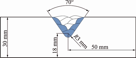
Fig. 1 Schematic view of multi-pass weld preparation
Table 2 Sequence of welding passes for each specimen
3 Results and discussion
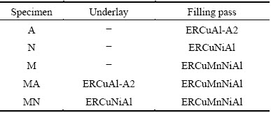
The microstructure of UNS C95700 base metal is shown in Fig. 2. It could be seen that the microstructure consisted of �� (dark phase), �� (light grains) and large ��1 precipitates (gray regions). The EDS spectrum of ��1 phase showed that this type of precipitations was rich in Fe, Mn and Si.
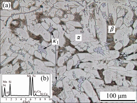
Fig. 2 Microstructure of UNS C95700 base metal (a) and EDS spectrum of ��1 phase (b)
The application of same welding parameters created a similar heat-affected zone (HAZ) in all specimens. In this region, the amount of �� phase decreased and the percentage of �� phase increased in comparison with the microstructure of the base material (Fig. 3(a)). In fact, some amount of �� phase has been transformed to �� phase during welding, while the high cooling rate of weld has prevented the subsequent formation of �� phase. The ��1 precipitates could not be solved due to the high melting temperature of these particles. According to Fig. 3(b), some fine precipitates are also observed in �� zone. More investigations should be done to characterize these tiny particles.
Fig. 3 Optical micrograph of HAZ (a) and SEM image of HAZ showing fine �� precipitates in �� phase (b)
The microstructure of weld metals is shown in Fig. 4. An epitaxial growth on the fusion line grains could be observed. The coarse ��1 precipitates were formed during solidification, and they remained in the final microstructure due to their stability at high temperatures.
According to Fig. 4(a), a coarse-grained micro- structure was observed in the weld A due to the lack of sufficient alloying elements. On the other hand, fine grains were found in the weld zone of specimens N and M (Figs. 4(b) and (c)). Also, the similarity between the base metal and the filler material in weld M resulted in the formation of homogeneous microstructure at the fusion line. No ��1 phase was detected in this weld.
In the case of specimen MA, the filler material of weld A was used for the underlay prior to the deposition of filling passes. As shown in Fig. 4(d), an unmixed zone was observed in this specimen (here named as ��transition zone��) and the microstructure of this region appeared similar to the microstructure of weld A. The same result was found for the specimen MN using the nickel-aluminum bronze underlay deposit (Fig. 4(e)).
The SEM images of welds are shown in Fig. 5. The high cooling rate and low alloying content of weld A produced the martensitic �� phase in the microstructure (Fig. 5(a)). The �� precipitates were observed between martensite layers and also in �� grains. The amounts of these precipitations were negligible due to the application of low alloying filer metal.
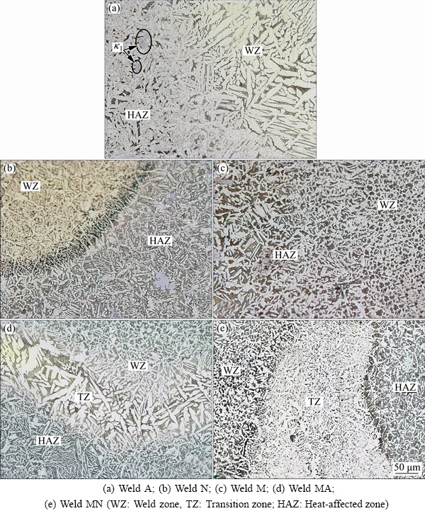
Fig. 4 Microstructures of weld regions
Ni could increase the solid solution limit of iron in aluminum bronzes and delay the formation of Fe-rich precipitates. Furthermore, Ni decreases the solid solution limit of aluminum. Therefore, the Ni-Al-rich ��3 precipitates with laminar morphology could form in the microstructure at higher percentages of Ni [13]. In specimen N, the high amount of Ni and low level of Mn caused the decomposition of �� phase to �� and ��3 phases according to Fig. 5(b). In specimen M, some round �� precipitates were found in �� phase as well as in �� phase, as shown in Fig. 5(c).
The application of electrode A with negligible alloying element contents for the first pass resulted in the lower Ni percentage of the weld MA compared with specimen M. The low Ni content of weld affected the solid solution limit of Fe. Therefore, the Fe-rich �� precipitates were formed at higher temperatures and their number in the microstructure of weld MA was higher compared with the microstructure of specimen M (Figs. 5(c) and (d)). On the other hand, the Ni percentage of weld MN was lower than that of weld N. No lamellar precipitates were observed in specimen MN while �� phase with the globular morphology was formed in �� and �� phases (Fig. 5(e)).
The grain size measurement showed that �� grains were considerably coarser in the microstructure of weld A in comparison with other specimens. This weld also contained the maximum amount of �� phase (approximately 80%) due to the less alloying element contents. Figure 6 presents the volume fraction of �� phase and ASTM grain size number for different welds. Weld M contained high percentage of Mn. Mn promoted the formation of �� phase in the microstructure; consequently, specimen M showed the lowest amount of �� phase in the weld microstructure (about 57%).
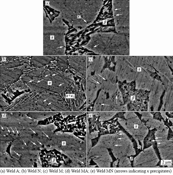
Fig. 5 SEM images of welds
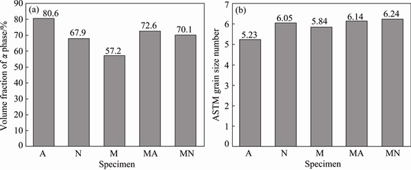
Fig. 6 Volume fraction of �� phase in microstructure of weld metals (a) and ASTM grain size number for each weldment (b)
The microhardness profiles for different specimens are shown in Fig. 7. The hardness increased from the base metal to the heat-affected zone. The high hardness of HAZ could be related to the transformation of �� phase to �� phase during welding. Weld A showed the lowest hardness among all specimens (less than the hardness of base metal) because of the high amount of �� phase, low alloying element content and coarse-grained microstructure. The application of this filler material in the first pass of weld MA exhibited low hardness values near the fusion line of this weld. The high percentage of �� phase in the microstructure of weld M, and fine-grained microstructure of weld MN with small size of globular �� precipitates exhibited the highest hardness levels in these specimens.
All transverse tensile samples were fractured in the base metal and presented similar strength values. This could be related to the as-cast microstructure of the base metal, and probably the existence of inherent casting defects. This showed that the tensile strength of weld metals was higher than that of the base material and consequently, the transverse tensile test was not capable of distinguishing between strength values of specimens. Therefore, the longitudinal samples were prepared for each weld metal; and the results are shown in Fig. 8.
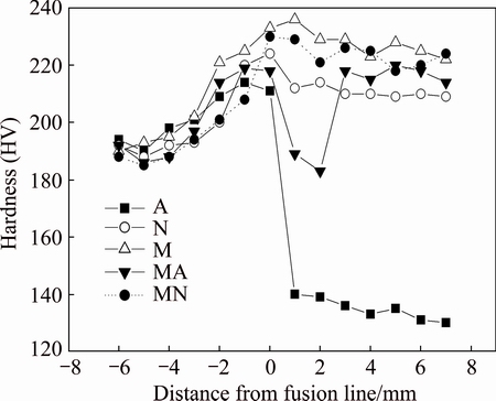
Fig. 7 Hardness profiles across weld for different specimens
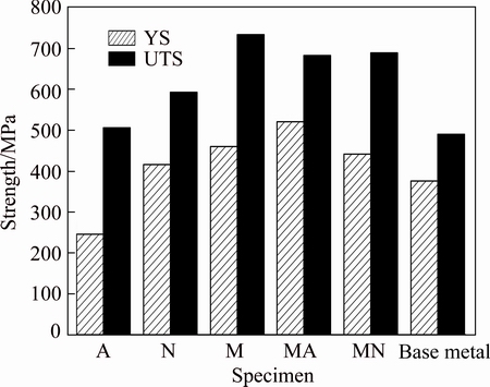
Fig. 8 Yield strength (YS) and ultimate tensile strength (UTS) of each weld
The high amount of �� phase, low alloying element content and coarse-grained microstructure resulted in the decreased strength of specimen A. It is suggested that the existence of brittle lamellar ��3 in the microstructure of weld N could reduce the strength of this weldment. The high tensile strength values were observed for specimens M, MA and MN containing high percentage of �� phase in their microstructures.
Figure 9 shows the results of bending test for the welded specimens. For welds M and MN, the fracture occurred at the interface of the weld and the parent metal. Also, the fracture of specimen N took place in the weld zone. Welds A and MA were bent fully 90�� without the occurrence of fracture; however, tiny surface cracks were found after completion of the test in weld A. The best combination of bending strength and deflection at mid-span was obtained for weld MA which combined the soft filler metal A and high strength filler metal M.
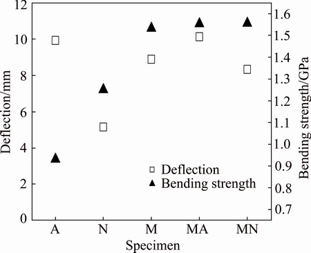
Fig. 9 Values of deflection at mid-span and bending strength for welded specimens
4 Conclusions
The effect of filler metal composition on the microstructure and mechanical properties of manganese- aluminum bronze repair welds was studied. The microstructure of welds was a mixture of ��, �� and �� precipitates with different morphologies. Mn suppressed the transformation of �� phase to �� phase, and the amount of �� phase decreased from 80% (Mn-free welds) to 57% (high Mn welds). Also, the morphology of �� precipitates was affected by the amount of Ni and Mn. The lamellar precipitates were observed in high Ni welds and globular morphology of precipitates was dominant in high Mn specimens. The high Ni filler metal could not improve the mechanical properties of weld. Although the filler material with similar chemical composition to the base metal was suggested for welding of aluminum bronze parts, the results showed that the application of non-alloy filler material for the underlay and high Mn filler metal for filling passes yielded the optimum mechanical properties of repair welds.
References
[1] MACKEN P J, SMITH A A. The aluminum bronzes-properties and production processes [M]. 2nd ed. St Albans: CDA Publication No 31, 1966.
[2] FONLUPT S, BAYLE B, DELAFOSSE D, HEUZE J L. Role of second phases in the stress corrosion cracking of a nickel�Caluminum bronze in saline water [J]. Corrosion Science, 2005, 47: 2792-2806.
[3] COUTURE A. Iron in aluminium casting��A literature survey [J]. Cast Metals Journal, 1981, 6: 9-17.
[4] CHEN R P, LIANG Z Q, ZHANG W W, ZHANG D T, LUO Z Q, LI Y Y. Effect of heat treatment on microstructure and properties of hot-extruded nickel-aluminum bronze [J]. Transactions of Nonferrous Metals Society of China, 2007, 17: 1254-1258.
[5] FULLER M D, SWAMINATHAN S, ZHILYAEV A P, MCNELLEY T R. Microstructural transformations and mechanical properties of cast NiAl bronze: Effects of fusion welding and friction stir processing [J]. Materials Science and Engineering A, 2007, 463: 128-137.
[6] IQBAL J, HASAN F, AHMAD F. Characterization of phases in an as-cast copper-manganese-aluminum alloy [J]. Journal of Materials Science and Technology, 2006, 22(6): 779-784.
[7] HASAN F, JAHANAFROOZ A, LORIMER G W, RIDLEY N. The morphology, crystallography, and chemistry of phases in as-cast nickel-aluminum bronze [J]. Metallurgical Transactions A, 1982, 13: 1337-1345.
[8] CULPAN E A, ROSE G. Corrosion behaviour of cast nickel aluminum bronze in sea water [J]. British Corrosion Journal, 1979, 14: 160-166.
[9] BREZINA P. Heat treatment of complex aluminum bronzes [J]. International Metals Review, 1982, 27: 77-120.
[10] CULPAN E A, ROSE G. Microstructural characterization of cast nickel aluminum bronze [J]. Journal of Materials Science, 1978, 13: 1647-1657.
[11] HASAN F, LORIMER G W, RIDLEY N. Crystallography of martensite in a Cu-10Al-5Ni-5Fe alloy [J]. Journal of Physics, 1982, 43: 653-658.
[12] OH-ISHI K, MCNELLEY T R. The influence of friction stir processing parameters on microstructure of as-cast NiAl bronze [J]. Metallurgical and Materials Transactions A, 2005, 36: 1575-1585.
[13] JAHANAFROOZ A, HASAN E, LORIMER G W, RIDLEY N. Microstructural development in complex nickel-aluminum bronzes [J]. Metallurgical Transactions A, 1983, 14: 1951-1956.
[14] SABOKTAKIN RIZI M, KOKABI A H. Microstructure evolution and microhardness of friction stir welded cast aluminum bronze [J]. Journal of Materials Processing Technology, 2014, 214: 1524-1529.
[15] NI D R, XUE P, WANG D, XIAO B L, MA Z Y. Inhomogeneous micro-structure and mechanical properties of friction stir processed NiAl bronze [J]. Materials Science and Engineering A, 2009, 524: 119-128.
[16] LABANOWSKI J, OLKOWSKI T. Effect of chemical composition and microstructure on mechanical properties of BA1055 bronze sand casting [J]. Advances in Materials Science, 2009, 9(1): 23-29.
[17] XU X, LV Y, HU M, XIONG D, ZHANG L, WANG L, LU W. Influence of second phases on fatigue crack growth behavior of nickel aluminum bronze [J]. International Journal of Fatigue, 2016, 82(3): 579-587.
[18] SONG Q N, ZHENG Y G, NI D R, MA Z Y. Studies on the nobility of phases using scanning Kelvin probe microscopy and its relationship with corrosion behaviour in chloride media for as-cast and friction-stir processed Ni-Al bronze [J]. Corrosion Science, 2015, 92: 95-103.
[19] VELU M, BHAT S. Metallurgical and mechanical examinations of steel�Ccopper joints arc welded using bronze and nickel-base superalloy filler materials [J]. Materials and Design, 2013, 47: 793-809.
[20] DEREK E, TYLER O C. Metals handbook [M]. Ohio: American Society for Metals, 1985.
[21] LI X Y, YAN Y G, MA L, XU Z M, LI J G. Cavitation erosion and corrosion behavior of copper-manganese-aluminum alloy weldment [J]. Materials Science and Engineering A, 2004, 382: 82-89.
[22] TANG C H, CHENG F T, MAN H C. Effect of laser surface melting on the corrosion and cavitation erosion behaviors of a manganese- nickel-aluminium bronze [J]. Materials Science and Engineering A, 2004, 373: 195-203.
[23] SABBAGHZADEH B, PARVIZI R, DAVOODI A, MOAYED M H. Corrosion evaluation of multi-pass welded nickel�Caluminum bronze alloy in 3.5% sodium chloride solution: A restorative application of gas tungsten arc welding process [J]. Materials and Design, 2014, 58: 346-356.
[24] NI D R, XIAO B L, MA Z Y, OIAO Y X, ZHENG Y G. Corrosion properties of friction-stir processed cast NiAl bronze [J]. Corrosion Science, 2010, 52: 1610-1617.
[25] LOTFOLLAHI M, SHAMANIAN M, SAATCHI A. Effect of friction stir processing on erosion-corrosion behavior of nickel-aluminum bronze [J]. Materials and Design, 2014, 62: 282-287.
[26] ASTM E855. Standard test methods for bend testing of metallic flat materials for spring applications involving static loading [S].
���϶�������ͭ����������֯����ѧ���ܵ�Ӱ��
M. R. MIRZADEH RAHNI, B. BEIDOKHTI, M. HADDAD-SABZEVAR
Materials and Metallurgical Engineering Department, Faculty of Engineering, Ferdowsi University of Mashhad, Mashhad, Iran
ժ Ҫ��ʹ�ò�ͬ�������϶�UNS C95700������ͭ����в������о�����������֯����ѧ���ܡ����������������Ҫ����֯Ϊ���в�ͬ��ò�Ħ����ºͦ��ࡣ�̵ļ���ʹ��������֯�Ц���ĺ�����80% (��Mn����)���͵�57% (12.5% Mn����)���ڸ��������Ц������òΪ��״�����ڸ��̺����Ц�����ò��Ϊ��״�������ʹ�ø������ϻ�õĺ��������ø��̺��ϻ�õĺ������нϸߵĿ���ǿ�Ⱥ�����ǿ�ȡ����ԷǺϽ���ERCuAl-A2Ϊ�ĵס����̺���(ERCuMnNiAl)Ϊ��亸�����в���ʱ����������ѧ������ѡ��˺����Ŀ���ǿ�ȱȻ�������Ŀ���ǿ�������39%���������������δ������������
�ؼ��ʣ�������ͭ�����ӣ����ϣ�����֯����ѧ����
(Edited by Wei-ping CHEN)
Corresponding author: B. BEIDOKHTI; Tel: +98-51-38805145; Fax: +98-51-38807182; E-mail: beidokhti@um.ac.ir
DOI: 10.1016/S1003-6326(17)60057-8

