Trans. Nonferrous Met. Soc. China 27(2017) 17-24
Microstructure analysis and mechanical characteristics of tungsten inert gas and metal inert gas welded AA6082-T6 tubular joint: A comparative study
E. R. IMAM FAUZI1, M. S. CHE JAMIL1, Z. SAMAD1, P. MUANGJUNBUREE2
1. Manufacturing Engineering Group, School of Mechanical Engineering, Universiti Sains Malaysia, 14300 Nibong Tebal, Penang, Malaysia;
2. Department of Mining and Materials Engineering, Faculty of Engineering, Prince of Songkla University, Hat Yai, Songkhla, 90112, Thailand
Received 16 November 2015; accepted 11 April 2016
Abstract: The present study is aimed to compare the microstructure characteristics and mechanical properties of AA6082 in T6 condition of tubular joints fabricated by tungsten inert gas welding (TIG) and metal inert gas welding (MIG) processes. The effect of welding processes was analysed based on optical microscopy image, tensile testing, and Vickers micro-hardness measurements. The results showed that the tensile strengths of the TIG-welded joints were better than those of the MIG-welded joints, due to the contribution of fine equiaxed grains formation with narrower spacing arms. In terms of joint efficiency, the TIG process produced more reliable strength, which was about 25% higher compared to the MIG-joint. A significant decay of hardness was recorded in the adjacent of the weld bead zone, shown in both joints, related to phase transformation, induced by high temperatures experienced by material. A very low hardness, which was about 1.08 GPa, was recorded in the MIG-welded specimens. The extent of the heat-affected-zone (HAZ) in the MIG-welded joints was slightly wider than those of the TIG-welded specimens, which corresponded with a higher heat input per unit length.
Key words: AA6082 aluminium alloy; tungsten inert gas (TIG); metal inert gas (MIG); mechanical properties; microstructure analysis
1 Introduction
The use of aluminium alloy for truss structures application has become an important alternative to conventional carbon steel, particularly for weight- sensitive systems [1]. Due to the favourable combination properties, the 6000 series aluminium alloys are being used extensively in structural application particularly in Europe and America [2]. Among the 6000 series aluminium alloy, 6082 is a relatively new material which can provide high strength properties, satisfactory corrosion resistance, good weldability, and machining performance [3]. Depending on material form and heat treatment, 6082 alloys can possess 12%-19% higher strength for characteristic values of ultimate tensile strength compared to 6061 alloy [4]. The preferred welding processes for these alloys are normally tungsten inert gas welding (TIG) and metal inert gas welding (MIG) due to their comparatively easier applicability and better economy [5].
Although TIG and MIG are widely used to successfully weld aluminium alloy, both processes have inherent different qualities of finished product depending on their process condition. High temperature generated during the welding process is responsible for the decay of mechanical properties, due to a metallurgical transformation of the material close to the welded joint and softening induced by alloying elements [6]. Observations suggested that in 6000 series aluminium alloys, the heat affected zone is the weakest region, even after natural aging happens. The softening effect can lead to the remarkable reduction of proof strength in the heat affected zone in the order of 30%-50%, and this region typically extends between 10-30 mm from the centre of the weld [7].
A significant research work comparing the welding stability of aluminium alloy is available in the literature [8-12]. For instance, ERICSSON and  [8] investigated the influence of welding speed on the fatigue strength of friction stir welding (FSW) by comparing the fatigue results with results of MIG-pulse and TIG. They used AA6082 specimens in T6 and T4 temper conditions. It was reported that the fatigue strength of FSW specimen was clearly higher than that of the MIG-pulse and TIG specimens.
  et al [9] compared the microstructure and mechanical characteristics of fusion welds (activated-TIG) and solid state welds (FSW) of Al-4.5Mg-0.26Sc heat-treatable aluminium alloy. The finding suggests that FSW weldment exhibits higher mechanical properties than those obtained by activated-TIG weldment. According to SQUILLACE et al [10], pitting corrosion resistance of AA2024-T3 FSW butt-joint was found to be asymmetric. ZHAO et al [11] further improved this finding by comparing the microstructure characteristics and mechanical properties of TIG and FSW joints of Al-Mg-Sc alloy. BENOIT et al [12] analyzed and compared the cladding operation of 6061 aluminium alloy using MIG, pulsed MIG, cold metal transfer MIG (CMT) and TIG processes. The weld beads were characterized by X-ray radiography, neutron diffraction, and micro-hardness mapping. It was found that the MIG processes generated higher residual stress and defect compared to the TIG process. Besides that, the CMT process produced the highest temperature and cooling rate amongst the others during the operation.
In this work, a comparison has been proposed on the mechanical properties and microstructure characteristics of AA6082 tubular joints realised with two different welding processes: a conventional TIG and MIG welding process. The TIG welding process uses an electric arc between a non-consumable electrode in tungsten and the material to be welded, shielded by an inert gas to protect the molten pool from atmospheric contamination. The typical TIG joint reveals different types of grain boundary according to particular welding speed. It is reported that the fine grains grow throughout the thickness of the weldment when using a higher welding speed (more than 19 mm/s). On the other hand, the wider grains aligned in the direction of heat source motion were obtained while using a lower speed (less than 7 mm/s) [13]. During the MIG welding process, an arc is maintained between a continuous solid wire electrode and the work piece, thereby causing a current flow which generates thermal energy in the partially ionised inert gas. The arc and the melt pool are shielded from atmospheric contamination by an inert or active gas. The typical microstructure of fusion zone of MIG joint contains dendrite structure with a wider arm spacing as compared to TIG joints [14]. In this study, both joints were specifically characterised according to yield strength, microhardness values and microstructure analysis. The performances provided by the entire joints are proposed. The characterisation of the microstructure of both welded joints at the locations of the fusion zone, fusion line, and heat affected zone is important in enhancing our understanding of welding processes and properties of the welded joints.

Fig. 1 Geometry of welded CHS specimen
2 Experimental
2.1 Specimen preparation
The material under investigation is a circular hollow section (CHS) of a commercial aluminium alloy AA 6082. Brace and chord structural elements were taken from the same series of extrusions, which have been produced under the same manufacturing conditions. The welded K-joint specimens, as shown in Fig. 1, consist of three identical CHS profiles with cross section diameter of 50.8 mm for both chord and brace. The wall thickness of the brace is 3.2 mm with 300 mm in length, and the wall thickness of the chord is 4.75 mm with 750 mm in length. The specimens taken were part of a massive scale of CHS bracing used for the structural system of a girder. The ends of each bracing in a girder have to be profile-shaped to fit the curvature of the chord member. Table 1 presents the main thermo-mechanical properties of AA 6082 alloy.
Table 1 General properties of aluminium alloy AA6082 [15]

In the TIG welding process, the tubular specimens were welded with a continuous current welding of 132 A, an input voltage of 22 V and a travel speed of 9.7 mm/min. The welding consumables were the AA4043 of 3.2 mm in diameter. Pure argon was used as shielding gas. The argon flow rate was set to be 20 L/min. The MIG welding parameters were set to be at 21.0 V, 250 A with a travel speed of 12 mm/min. Pure argon was used to shield the molten pool. The flow rate of argon was set to be at 20 L/min. The AA4043 of 1.6 mm in diameter was used as a consumable. To reduce distortion, the welding sequence around the circumference of the brace was split into two separate beads, beginning at the same corner location and ending at the opposite corner. Table 2 summarized the chemical composition of the AA6082 alloy, obtained from an energy-dispersive X-ray spectroscopy (EDX) analysis.
Table 2 Chemical composition of AA 6082 aluminium alloy (mass fraction, %)

2.2 Tensile test
The tensile properties of both welded and unwelded specimens were tested with a velocity of 10 kN/min on the Shimadzu Universal Tensile Machine. A steel rod was inserted into both ends of the full-scaled tubular aluminium specimen during the tensile test to prevent the test machine’s grip jaws from crushing the test samples. Tensile tests were performed in accordance with the established standards of ASTM A370.
2.3 Micro-hardness test
Micro-hardness testing provides an objective evaluation of weld strength across the parent metal: HAZ region and fusion zone. The test was performed by forcing a diamond-shaped indenter with the angle of 136° onto the specimen’s surface. To obtain valid results, the flatness of the specimen’s surface is essential. Therefore, specimens were cut in a perpendicular direction to the weld bead for analysis. Specimens were then mirror-like polished before performing the indentation. Vickers microhardness test measurements were carried out with a 200 g load at a 10 s dwell-time in the transverse cross-section of the welded joints by using Shimadzu microhardness Type M tester. The Vickers indentation along the centre line of the chord member, as shown in Fig. 2, was intentionally performed to investigate the distribution of the hardness profile to correspond to the width of the HAZ. The distance between each indentation is 0.5 mm.

Fig. 2 Extracted specimen’s part for micro-hardness test
The hardness of the material represents the plastic deformation resistance by indentation. In common practice, the Vickers harness number H, with a pyramidal square-based indenter is calculated considering the true contact area, where
 (1)
(1)
where H is expressed in MPa if P, the applied load, is given in N and d, the indentation diagonal, in mm.
2.4 Microstructure analysis
Micrographic analysis was carried out using scanning electrons microscope (SEM). Specimens for SEM analysis were prepared according to the standard metallographic procedure [16]. Mechanical grinding was performed using silicon carbide (SiC) abrasive papers of 400, 600, 800, and 1200 grit. 6 μm diamond paste was used for a rough polishing. The final step of polishing was carried out using 1 μm of polycrystalline alumina (Al2O3) on a woven polishing pad. In order to reveal the grain boundary contrast in the welded specimens, an etchant of sodium hydroxide (NaOH) solution was used. The specimens were immersed in NaOH solution heated to 60-70 °C for about 15 min before dipped in 65% of nitric acid (HNO3) solution.
3 Results and discussion
3.1 Morphological analysis
During the welding process, three different regions were produced, which are 1) the fusion zone (FZ), 2) partially-melted zone (PMZ), and 3) the heat affected zone (HAZ). These regions are categorised according to the temperature experienced during welding. Figure 3 illustrates the grain boundary of the TIG welded specimen under magnification of 25. All materials lying within the FZ is completely melted into a liquid state during the welding process with thermal heat beyond the liquidus temperature of the alloy. Weld defects such as solidification cracking, porosity, and loss of alloying elements may occur in this region. It can be observed that the grain structure in the TIG-welded specimen primarily consists of coarse equiaxed grains with non-epitaxial growth. The fusion boundary exhibits random misorientation between parent metal grains and weld metal grains. The characteristics and distribution of the microstructure in the fusion zone depends on the solidification behaviour of the weld pool. The solidification mode of the grains changes rapidly as the constitutional supercooling increases. This promotes the heterogeneous nucleation of equiaxed grains at the fusion boundary. The PMZ lies just outside the fusion line. This region is part of the HAZ where the peak temperature has exceeded the equilibrium solidus temperature. In the PMZ, cellular grain growth dominates the structural transformation. Due to high-temperature gradient towards the weld pool, the grains have the tendency to solidify, mainly upwards and towards the fusion line. From Fig. 3, it can be seen that the morphology of the microstructure varies noticeably from the edge of fusion line to the centre line of the weld. This formation can be explained as follows: the growth rate R of the grains is low along the fusion line and increases toward the centre line of weld. The solid around the weld pool acts as a heat sink and lead to a higher temperature gradient, G along the fusion line. Since the ratio of G/R decreases from the fusion line towards the centre line of the weld, the solidification mode changes significantly from cellular to equiaxed grains across the PMZ and FZ [17].

Fig. 3 SEM images of TIG-welded aluminium alloy 6082 at different magnifications

Fig. 4 SEM images of MIG-welded aluminium alloy 6082 at different magnifications
Figure 4 shows an overview and close-up of the fusion zone microstructure in the MIG-welded specimen. The grain in the fusion zone consists of smaller equiaxed grains as compared to the grain size of the TIG-welded specimen. The grains on the fusion line appear to have more columnar appearance. The grain spacing is marginally wider in the MIG-welded specimen as compared to the TIG-welded specimen. Some evidence of epitaxial growth of columnar grains can be observed along the intersection between the HAZ and FZ. However, the PMZ in the MIG-welded specimen is not visible. From Fig. 4, it can be seen that apparent pore formation was formed in the weld metal. These faulty defects were scattered particularly at the edge of the weld joint and at the centre of the weld metal. It arises from gas dissolved in the molten weld metal and becoming trapped as it solidified, thus forming gas pores in the solidified weld.

Fig. 5 Fracture section of unwelded (a) and welded (b) specimen
3.2 Tensile properties
The tensile properties of the unwelded specimen, TIG-welded specimen, and MIG-welded specimen are presented in Table 3. The results show a remarkable reduction in yield strength and tensile strength of welded specimens as compared to nominal values of the unwelded parent metal. The yield strength and tensile strength of the unwelded specimens are 308.21 MPa and 318.92 MPa, respectively. The fracture location of the unwelded specimen is almost at the centre as shown in Fig. 5(a). Meanwhile, for both the MIG and TIG welded specimens, the fracture was observed in the region between the two bracing members (Fig. 5(b)). The higher strength of the base metal is mainly attributed to the presence of alloy elements such as silicon and magnesium. The formation of Mg2Si precipitate provides greater strength and hardness to the parent metal [18]. However, the yield strength and tensile strength of TIG-welded specimens are 203.56 MPa and 257.20 MPa, respectively. This indicates that there is a 19.4% reduction in strength value due to TIG welding.
Table 3 Tensile properties of unwelded and welded specimens

Similarly, the yield strength and tensile strength of MIG-welded specimens is 141.83 MPa and 205.71 MPa, respectively, which are 35.5% lower compared to the parent metal. According to  [19], the noticeable reduction in mechanical strength is due to the depletion of Mg2Si precipitates during the process and also softening by annealing in the heat affected zone. This phenomenon can be explained as follows: during the welding process, a large amount of silicon is available through the addition of the AA4043 filler metal. However, the amount of magnesium in the molten pool is lower compared to that of silicon because magnesium is only available from the parent metal. Hence, fewer Mg2Si precipitates were formed in the weld region. In consequence, the weld area is weaker compared to the parent metal due to the depletion of Mg2Si precipitates. Additionally, a significant loss of strength in heat affected zone is due to precipitation reactions involving coarsening. The extent of coarsening depends greatly on the peak temperature experienced during welding and, hence, distance from the fusion boundary. In the case of the 6000 series alloy, some of the Mg2Si precipitates can respond to post-weld aging and allow for the partial recovery of strength, as suggested by MYHR et al [20].
In addition to the tensile values of the specimens, the efficiency of each joint was calculated as shown in Table 3. Joint efficiency is calculated as the ratio between the tensile strength of welded joint and the tensile strength of unwelded parent metal. The joint efficiency of TIG tubular joint is approximately 80.6%, whereas only 64.5% joint efficiency is accounted for in the MIG joint.
3.3 Microhardness profiles
The distribution of microhardness profile of both TIG-welded and MIG-welded specimens is shown in Fig. 6(a), along with the schematic representation of the microstructure change in Fig. 6(b). It was found that the distribution of microhardness of both specimens is almost symmetric on both sides of the weld region. In the case of the TIG-welded specimen, the minimum hardness value is about 1.1 GPa, which was measured in the adjacent of the weld bead zone. Here, the microstructures were treated by solubilization and will age in a natural manner through a higher cooling rate. The region within points A and B is called over-ageing zone, where the temperature during welding is below the solvus temperature. Thus, the influence of heat input reduces with the increase of distance from the weld, and so the properties of the parent material are valid from point A onwards. The hardness is at its minimum value at point B, where the isotherm zone appears within HAZ, for which the obtained temperature is located between two well-defined temperatures, i.e., the artificial aging temperature of the alloy and the solvus temperature. Hence, microstructure evolution takes place due to thermodynamic instability.
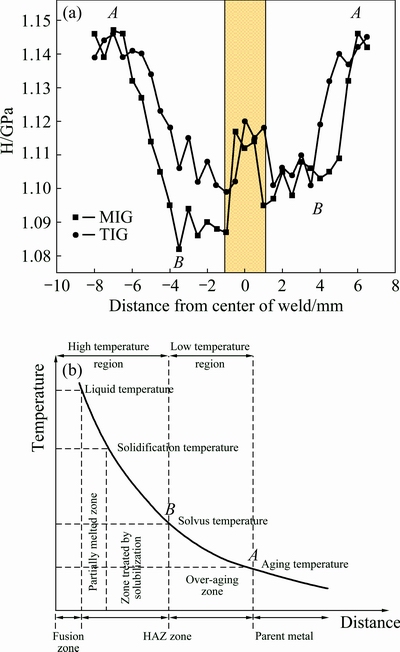
Fig. 6 Distribution of microhardness of MIG-welded and TIG-welded specimens of AA6082-T6 (a) and schematic representation of microstructural changes in heat treatable aluminium alloys during a fusion welding process (b)
The hardnesses of the welded specimens are related closely to the microstructure transformation experienced in HAZ. Two factors of great importance in understanding microstructure changes in HAZ include peak temperature and cooling rate. The cooling rate is inversely proportional to the heat energy, which is also expressed in terms of welding heat input:
 (2)
(2)
where K is thermal conductivity, v is velocity of heat source, η is arc efficiency, I is welding current, V is welding voltage, T is temperature, T0 is preheat temperature and Qw is welding heat input (Qw=ηIV/v). Thus, higher heat input results in a higher peak temperature at a given distance from the weld centre, which in turn results in slower cooling rate.
In TIG welding, since alternating current polarity is used, the maximum heat input is not fixed as the heat is continuously changing between the electrode and the workpiece in order to melt the filler rod and workpiece. Besides that, a large diameter of filler rod (3.2 mm) reduces the current density [21]. Therefore, lower arc temperature was attained, causing fast cooling rate. This, in turn, produces narrower grain spacing. Thus, only slight reduction was observed in the hardness value and tensile properties. The significant decrease of microhardness values was found at the beginning of the HAZ, which is about 4 mm from the weld centre, followed by a slight increase in the weld bead zone. Due to age hardening effect, a small increment of microhardness value was detected in the area within the HAZ. For the MIG-welded specimens, the hardness value drops in the HAZ with a minimum of 1.08 GPa; this is 30% lower than the TIG-welded specimen. This phenomenon was influenced by the heat of the welding process. Since the MIG process uses a small diameter of filler wire (1.6 mm) as a consumable electrode and is always connected to the direct current, the heat generation and the current density are very high. Thus, it enhances the arc temperature and molten pool temperature [22]. This will lead to a slow cooling rate, which in turn, produces relatively wider grain spacing. These microstructures offer lower resistance to indentation, and hence, resulting in a lower microhardness value and tensile properties in the MIG-welded specimens. Furthermore, the width of HAZ for the MIG-welded specimens was slightly wider than that of the TIG-specimens, which corresponds with a higher heat input of the material per unit length (Refer to Appendix A for heat input calculation). In the case of the MIG-welded specimens, full recovery of the base metal hardness was observed approximately 6 mm from the centre of the weld on both sides.
4 Conclusions
1) The joints fabricated by the TIG process exhibited higher mechanical strength value compared to the MIG-welded specimens. The enhancement in strength value was approximately 25%. In terms of joint efficiency, the TIG process produced more reliable strength, which was about 25% higher compared to the MIG-joint.
2) The hardness values were reduced remarkably in the HAZ regardless of the welding techniques. A very low hardness value, which was about 1.08 GPa, was recorded in the MIG-welded specimens.
3) The grain characteristics of the weld region played a major role in deciding the joint properties. The formation of fine, equiaxed grains was influenced by the heat generation and cooling rate during the welding process.
Acknowledgements
The authors are grateful to the University Science Malaysia (USM) and Malaysia Ministry of Education (MoE) for their technical and financial support. They wish to thank Mr. Mohd Ashamuddin Hashim for providing technical support in conducting the analysis. This research was funded by USM through research grant 1001/PMEKANIK/814235.
Appendix A
Calculation of heat input during welding with voltage in volt (V), current in amps (I), percentage efficiency (η), and speed in mm/min (v).
For TIG-welding process:


For MIG-welding process:

References
[1] MAZZOLANI F M. 3D aluminium structures [J]. Thin-Walled Struct, 2012, 61: 258-266.
[2] KISSELL J, FERRY R. Aluminium structures―A guide to their specifications and design [M]. 2nd ed. New York: John Wiley & Sons, 2002.
[3] MAZZOLANI F M. Aluminium alloy structures [M]. 2nd ed. London: Chapman & Hall, 1995.
[4] EUROCODE 9. Design of aluminium structures. Part1-1: General structural rules. EN-1999-1-1 [S]. Brussels, 2007.
[5] MADHUSUDHAN R G, GOKHALE A, PRASAD R K. Optimization of pulse frequency in pulsed current gas tungsten arc welding of aluminium-lithium [J]. Journal of Materials Science & Technology, 1998, 14: 61-66.
[6] MARKOVITS T, TAKACSA J, LOVAS A, BELT J. Laser brazing of aluminum [J]. Journal of Materials Processing Technology, 2003, 143-144: 651-655.
[7] COLLETTE M. The impact of fusion welds on the ultimate strength of aluminum structures [C]//Proceedings of 10th International Symposium on Pratical Pesign of Ships and Other Floating Structures. Houston, USA. 2007.
[8] ERICSSON M, R. Influence of welding speed on the fatigue of friction stir welds, and comparison with MIG and TIG [J]. International Journal of Fatigue, 2003, 25: 1379-1387.
[9]  G, HUNEAU B, SAUVAGE X, MARYA S. Comparison of TIG welded and friction stir welded Al-4.5Mg- 0.26Sc alloy [J]. Journal of Materials Processing Technology, 2008, 197: 337-343.
[10] SQUILLACE A, de FENZO A, GIORLEO G, BELLUCCI F. A comparison between FSW and TIG welding techniques: Modifications of microstructure and pitting corrosion resistance in AA 2024-T3 butt joints [J]. Journal of Materials Processing Technology, 2004, 152: 97-105.
[11] ZHAO J, JIANG F, JIAN H, WEN K, JIANG L, CHEN X. Comparative investigation of tungsten inert gas and friction stir welding characteristics of Al-Mg-Sc alloy plates [J]. Materials & Design, 2010, 31: 306-311.
[12] BENOIT A, PAILLARD P, BAUDIN T, KLOSEK V, MOTTIN J B. Comparison of four arc welding processes used for aluminium alloy cladding [J]. Science and Technology of Welding and Joining, 2015, 20: 75-81.
[13] NORMAN A, DRAZHNER V, PRANGNELL P. Effect of welding parameters on the solidification microstructure of autogenous TIG welds in an Al-Cu-Mg-Mn alloy [J]. Materials Science and Engineering A, 1999, 259: 53-64.
[14] LAKSHMINARAYANAN A, BALASUBRAMANIAN V, ELANGOVAN K. Effect of welding processes on tensile properties of AA6061 aluminium alloy joints [J]. International Journal of Advanced Manufacturing Technology, 2009, 40: 286-296.
[15] BRITISH STANDARD BS 8118: Part 1: 1991 [S]. London, 1991.
[16] GEORGE F V V. ASM handbook on metallography and microstructures [M]. Vol. 9. Material Park, Ohio, USA: ASM International, 2004.
[17] SAVAGE W F, ARONSON A H. Preferred orientation in the weld fusion zone [J]. Welding Journal, 1966, 45: 85-89.
[18] MONDOLFO L. Aluminium alloys-structure and properties [M]. London: Butterworths, 1997.
[19] G. Influence of chemical composition variation and heat treatment on microstructure and mechanical properties of 6xxx alloys [J]. Archives of Materials Science and Engineering, 2010, 46: 6-13.
[20] MYHR OR, GRONG  Process modelling applied to 6082-T6 aluminium weldments―I. Reaction kinetics [J]. Acta Metallurgica et Materialia, 1991, 39: 2693-2702.
[21] MADHUSUDHAN R G, MOHANDAS T, CHANDRESHEKAR K. Observations on welding of α2+O+β titanium aluminide [J]. Science and Technology of Welding and Joining, 2001, 6: 300-304.
[22] POTLURI N, GHOSH P, GUPTA P, REDDY Y. Studies on weld metal characteristics and their influences on tensile and fatigue properties of pulsed current GMA welded Al-Zn-Mg alloy [J]. Welding Journal, 1996, 75: 62-70.
钨极惰性气体保护焊和金属惰性气体保护焊AA6082-T6管状接头显微组织与力学特性的对比研究
E. R. IMAM FAUZI1, M. S. CHE JAMIL1, Z. SAMAD1, P. MUANGJUNBUREE2
1. Manufacturing Engineering Group, School of Mechanical Engineering, Universiti Sains Malaysia, 14300 Nibong Tebal, Penang, Malaysia;
2. Department of Mining and Materials Engineering, Faculty of Engineering, Prince of Songkla University, Hat Yai, Songkhla, 90112, Thailand
摘 要:采用钨极惰性气体保护焊和金属惰性气体保护焊两种工艺对T6态AA6082合金管进行焊接,比较所得焊接接头的显微组织特性和力学性能。利用光学显微镜,拉伸测试和显微硬度测试研究焊接工艺的影响。结果表明,由于形成了细小的等轴晶且枝晶间距较小,TIG焊接接头的拉伸强度比MIG焊接接头的拉伸强度高,强度可提高25%。在焊接效率方面,TIG焊接可得到更可靠的强度,与MIG焊接相比,其强度可提高25%。两种焊接工艺焊缝区的硬度都大幅度降低,这是由于高温时材料发生了相变。MIG焊接样品的硬度较低,为1.08GPa。MIG焊接接头的热影响区比TIG焊接接头的稍大,这是由于单位长度的热输出更大。
关键词:AA6082铝合金;钨极惰性气体保护焊;金属惰性气体保护焊;力学性能;显微组织分析
(Edited by Yun-bin HE)
Corresponding author: E. R. IMAM FAUZI; Tel: +60-19-5585785; E-mail: erif14_mec009@student.usm.my
DOI: 10.1016/S1003-6326(17)60003-7

