�����ʱЧ������Ti-6Al-4V�Ͻ���ܳ����Ϊ��Ӱ��
��Դ�ڿ����й���ɫ����ѧ��(Ӣ�İ�)2017���3��
�������ߣ�N. YUMAK K. ASLANTAS Y. PEKBEY
����ҳ�룺514 - 526
�ؼ��ʣ�Ti-6Al-4V�Ͻ����䴦����ʱЧ���������ܳ��ʵ�飻������ˣ����ͷ������״
Key words��Ti-6Al-4V alloy; cryogenic treatment; aging treatment; low-energy impact test; impact damage; impactor nose geometry
ժ Ҫ���о������ʱЧ������Ti-6Al-4V�Ͻ���ǿ�Ⱥ���ѧ���ܵ�Ӱ�졣��Ti-6Al-4V�Ͻ�ֱ�������䴦��(CT)��ʱЧ����(AT)�Լ��������ʱЧ����(CAT)���ò�ͬ������״(��Բ�Ρ�60���90����)�ij��ͷ�Ծ��ȴ�����δ���ȴ���Ti-6Al-4V��Ʒ���г��ʵ���Կ�����ͷ������״����Ʒ�������Ե�Ӱ�졣��������������ȴ�����Ʒ�����������Ӷ�����������͡������������������ӣ�CAT��Ʒ������ߵ�������������С�������������δ����������Ʒ���������Ρ����⣬���ͷ�ļ�����״����Ʒ�����������ƫ������������Ӱ�졣ʹ��60���dz��ͷ���г��ʵ�����Ʒ��������ƫ����(��)����С�����������Ʒ�ı����������ͷ�ǵ����������
Abstract: The objective of this study is to examine the effects of cryogenic and aging treatments on the impact strength and mechanical properties of Ti-6Al-4V alloy. To accomplish that objective, cryogenic treatment (CT), aging treatment (AT) and cryogenic treatment followed by aging treatment (CAT) were conducted on Ti-6Al-4V alloy. Impact tests were performed on heat-treated and untreated samples using different impactor nose geometries (hemispherical, 60�� and 90�� conical) to determine the effect of impactor nose geometry on the damage characteristic. The findings showed that energy absorption increased and areas of damage decreased as a result of heat treatment in all treated samples. The highest energy absorption was observed in the CAT samples, due to the increase in energy absorption, the smallest damaged area occurred in the CAT sample, and the largest deformation was seen in the untreated samples. Additionally, it was seen that the damaged area and deflection were strongly dependent on impactor nose geometry. The maximum deflection and narrowest deformation area were seen with 60o conical nose geometry. The deformation area increased with increasing impactor nose angle.
Trans. Nonferrous Met. Soc. China 27(2017) 514-526
N. YUMAK1, K. ASLANTAS1, Y. PEKBEY2
1. Department of Mechanical Engineering, University of Afyon Kocatepe, Afyon-03000, Turkey;
2. Department of Mechanical Engineering, University of Ege,  -35030, Turkey
Received 8 March 2016; accepted 24 August 2016
Abstract: The objective of this study is to examine the effects of cryogenic and aging treatments on the impact strength and mechanical properties of Ti-6Al-4V alloy. To accomplish that objective, cryogenic treatment (CT), aging treatment (AT) and cryogenic treatment followed by aging treatment (CAT) were conducted on Ti-6Al-4V alloy. Impact tests were performed on heat-treated and untreated samples using different impactor nose geometries (hemispherical, 60�� and 90�� conical) to determine the effect of impactor nose geometry on the damage characteristic. The findings showed that energy absorption increased and areas of damage decreased as a result of heat treatment in all treated samples. The highest energy absorption was observed in the CAT samples, due to the increase in energy absorption, the smallest damaged area occurred in the CAT sample, and the largest deformation was seen in the untreated samples. Additionally, it was seen that the damaged area and deflection were strongly dependent on impactor nose geometry. The maximum deflection and narrowest deformation area were seen with 60o conical nose geometry. The deformation area increased with increasing impactor nose angle.
Key words: Ti-6Al-4V alloy; cryogenic treatment; aging treatment; low-energy impact test; impact damage; impactor nose geometry
1 Introduction
Ti-6Al-4V is a titanium alloy that is widely used in the biomedical, aerospace, automotive, space, and other major industries due to its low density, high strength and excellent corrosion resistance specifications. The development of mechanical properties and determination of the deformation behaviour of Ti-6Al-4V alloy under various loads are of importance when the specific applications of the alloy are considered. Due to the sensitivity of the heat treatment of Ti-6Al-4V alloy, it was determined that its mechanical properties could be developed [1-4]. The effects of changes in the microstructure of Ti-6Al-4V alloy on its mechanical properties as a result of different heat treatment procedures have been investigated by many authors in the literature. In particular, �� phase transforms, �� and �� phase morphology, �� plate thickness, and the spacing between the plates are the most studied topics [5-7].
One of these treatments is cryogenic treatment, which is frequently implemented to develop the mechanical properties of the alloy. Cryogenic treatment is a low-cost treatment applied once with homogeneous effects on materials that are widely used in the aerospace and automotive industries to increase wear resistance and ensure dimensional stability [8]. In previous studies, it was observed that the tensile and yield strengths of the material decreased slightly, but elongation and reduction of the area and hardness increased by 10.5%, 13.5%, and 2.5%, respectively. Cryogenic treatment tends to change the phase, which prevents the movement of dislocations and therefore decreases plastic deformation [1,2]. Another study about the effect of cryogenic treatment on the wear resistance of Ti-6Al-4V alloy showed that the hardness and wear resistance of the alloy increased due to the reduction of �� phase [9]. Although the effects of cryogenic treatment on the mechanical properties are known, its effects on impact resistance and damage behaviour have not been completely explained. This study scrutinized the effects of cryogenic treatment on the impact resistance, deformation behaviour, and mechanical properties of the alloy. Along with the cryogenic treatment, the second heat treatment frequently applied to the alloy is aging treatment. VENKATESH et al [3] applied aging treatment to Ti-6Al-4V alloy using different cooling procedures. It was observed that a hard layer was formed on the material as a result of the heat treatments with the aging treatment and this layer affected the mechanical properties of the material. SINGH et al [4] solution-treated the alloy under and over the �� transition temperature and then applied aging treatment. Aging-treated samples were ballistic tested with a 7.62 mm-calibre bullet. The ballistic test results showed that the energy absorption of the samples increased, while the amount of back plate deflection and crack formations decreased.
During the impact and ballistic tests, it was observed that the impact nose geometry and impact energy level were the most significant factors affecting the impact resistance of the material [10-14]. Impactor nose geometries were evaluated in three main groups in the literature based on the deformation characteristics that they caused in the material. These are hemispherical, blunt, and changing nose-angle conical geometries [11-16]. Each geometry has different impact characteristics and causes failure of the material. Blunt impactor nose geometries cause failure modes by plugging. Hemispherical and conical geometries penetrate the samples by increasing the compressive stress due to the nose angle and pushing the material from the top face to the back face [10,11]. Blunt impactor nose geometry causes a wider deformation area compared with the hemispherical and conical geometries [8]. However, as the impact energy increases, the blunt impactor geometry causes a smaller deformation area compared with the hemispherical and conical impactor geometries [15,16]. Thus, as the energy levels increase, the deformation characteristics differ as well [16]. Therefore, it would be beneficial to scrutinizing the impactor geometry and impact energy levels together when researching the impact characteristics. In the present work, the effects of the energy level and impactor nose geometries on the impact behaviour of Ti-6Al-4V alloy were examined together.
In the light of those studies, it could be stated that cryogenic and aging treatments increased the mechanical properties of the Ti-6Al-4V alloy. Therefore, it would be correct to assume that these heat treatments could increase the impact resistance of the alloy. Thus, cryogenic treatment, aging treatment, and cryogenic treatment followed by aging treatment were applied to the alloy in this work. Following the heat treatment, in order to investigate extensively the low-energy impact behaviour of the Ti-6Al-4V alloy, low energy impact tests were conducted on samples.
2 Experimental
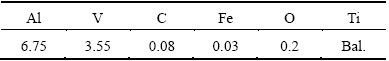
The experimental works were completed in four steps: 1) heat treatment procedures of Ti-6Al-4V alloy; 2) mechanical testing; 3) low energy impact tests; and 4) investigation of damaged zone and observation of damage modes. The chemical composition of Ti-6Al-4V alloy is shown in Table 1.
Table 1 Chemical composition of Ti-6Al-4V alloy (mass fraction)
2.1 Heat treatment procedures
In this work, cryogenic treatment, aging treatment, and cryogenic treatment followed by aging treatment were conducted on annealed Ti-6Al-4V alloy containing a lamellar ��-phase with larger ��-grains. Ti-6Al-4V alloy is a two-phase titanium alloy, with aluminium as �� stabilizer and vanadium as �� stabilizer. In order to investigate the low-energy impact behaviour of Ti-6Al-4V alloy, four different sample groups were tested; the details of the sample groups and codes are shown in Table 2.
Table 2 Details of codes of heat-treated samples
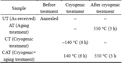
Ti-6Al-4V alloy plates were cut to dimensions of 100 mm �� 100 mm �� 2 mm according to the dimensions of the pneumatic clamping device of the low-energy impact test machine. After the plates were cut, cryogenic treatment was applied to the samples at -140 ��C for 6 h under a protective nitrogen atmosphere using a vacuum oven. The cryogenic treatment temperature and soaking time were determined according to the results of studies performed previously in Refs. [1,2,9]. The cryogenic treatment tank is shown in Fig. 1(a) and illustrated schematically in Fig. 1(b).
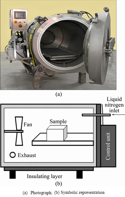
Fig. 1 Procedure of cryogenic treatment
The cryogenic treatment system consists of a cryogenic treating tank, nitrogen tank, liquid nitrogen inlet system, fan, control panel, and an outer cladding structure providing insulation. Liquid nitrogen is pumped into the cryogenic tank, where evaporated nitrogen is spread uniformly within the entire tank with the help of the fans. The atmosphere is time and temperature controlled in the system: the sample is cooled to cryogenic treatment temperature and then warmed to room temperature again, and the cycle was completed when room temperature was reached. Nitrogen was evaporated by increasing the temperature removed via the exhaust. To prevent heat loss and obtain homogeneous material property, the cryogenic tank was covered with a second insulating layer. After completion of soaking at -140 ��C, the materials were warmed up to room temperature of 20 ��C. To avoid thermal shock, the materials were cooled at a rate of 1 ��C/min. The temperature of aging treatment of Ti-6Al-4V alloys ranged from 450 to 650 ��C; in this study, the aging treatment was conducted at 550 ��C. AT was performed using a heat-controlled resistance furnace. The samples were subjected to aging treatments at a temperature of 550 ��C for 3 h in the argon atmosphere at a flow rate of 6.3 L/min. For the CAT samples, cryogenic treatment at -140 ��C for 6 h was followed by aging treatment at 550 ��C for 3 h in the argon atmosphere at the same flow rate as AT samples. The heat treatment cycle of the CAT samples is given in Fig. 2.
Microstructure analysis was carried out for all samples by using optical microscopy. To prepare samples for optical microscopy analysis, they were ground, polished, and finally etched with Kroll solution (consisting of 5% HF, 10% HNO3, and 85% distilled H2O, volume fraction) for 40 s.

Fig. 2 Heat treatment cycle of CAT samples
2.2 Mechanical testing
The samples treated by different treatment procedures and the untreated ones were tested to analyze their tensile and hardness properties. A Shimadzu universal tensile testing machine was used to test the tensile properties of the samples according to ASTM E8-04. Tensile test specimens were prepared according to the American Standard of ASTM E8-04, as shown in Fig. 3. The elongations of samples were determined by considering the difference between fracture length and the initial length of specimens. All tests were conducted at a velocity of 2 mm/min and room temperature, repeated five times and then averaged to give the final value.

Fig. 3 Dimensions of tensile test samples (unit: mm)
After the tensile tests, the fracture surfaces of test specimens were examined using a model LEO 1430 VP scanning electron microscope (SEM). Hardness tests were carried out using a digital Vickers hardness test machine under a load of 100 N and the tests were repeated five times.
2.3 Low-energy impact tests
Low-energy impact tests were carried out on untreated and heat-treated samples with dimensions of 100 mm �� 100 mm �� 2 mm and three different impactor nose geometries in order to find the effect of heat treatment on the impact behaviour of Ti-6Al-4V alloy. An Instron Dynatup 9250 HV low-energy impact test machine was used to perform tests. The main parts of the system are the drop tower consisting of the impactor, 22 kN load-cell, velocity indicator/time sensor, and data collection system for obtaining force-time curves. The other impact test results of velocity and deflection were gathered from force/time data according to Newton��s second law. The drop height and impactor mass were varied to obtain different impact energies. The total mass of the load cell and impactor was approximately 5 kg. Other parts of the test system, i.e., the control box, rebound break, emergency stop, impactor, environmental chamber, and control unit, have a temperature range of -51 to +177 ��C and are shown in Fig. 4(a).
The samples were put into the environmental chamber and fixed with a pneumatic clamping device and the tests were conducted at room temperature. The inner diameter of the clamping apparatus was 80 mm. Low-energy impact tests were performed at the energy levels of 40, 60 and 80 J determined by tests done before. In order to investigate the effects of the impactor nose geometry on the damage characteristic of the alloy, three different nose geometries were designed. The impactor nose geometries are shown in Figs. 4(b) and (c). The impactors were made of DIN 1.2550 cold work tool steel. The hemispherical impactor nose geometry was coded as D12.7, the 60�� conical geometry as A60, and the 90�� conical geometry as A90. Each test was repeated twice and a total of 72 impact tests were carried out. After the tests, damaged areas on the front and back faces of the samples were photographed to calculate the total damaged area of samples. The damage areas were found by calculating the area of a circle considering the longest crack length as the diameter. After the impact test, the fracture surfaces were detected by SEM to analyze the failure mode formation.
3 Results and discussion
3.1 Microstructure
The microstructure of Ti-6Al-4V alloy consists of �� and �� phases; �� phase is a hexagonal close-packed (HCP) structure and �� phase is a body-centred cubic (BCC) structure. In the micrographs of untreated (UT) samples, white regions represent �� phase and black regions represent �� phase, as shown in Fig. 5. Al and V elements are the main elements that stabilize the ��+�� phase; the other elements in the compound are O, N, C and Fe and they play an important role in the metallurgic stability of this alloy. Because of the complexity of the microstructure, the application of different heat treatments causes the formation of different microstructures and mechanical properties [1,2,9,18].
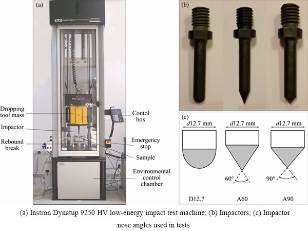
Fig. 4 Low-energy impact test procedure
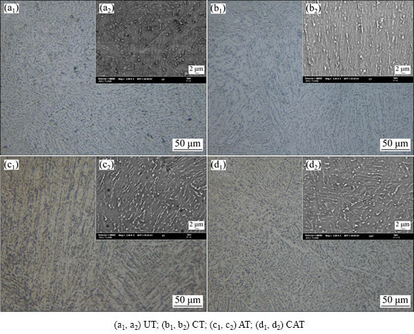
Fig. 5 OM (a1-d1) and SEM (a2-d2) images of heat-treated and untreated samples
The �� phase transformations, �� and �� phase morphologies, �� plate thickness, and spacing between the plates after the heat treatment process are the most commonly studied topics. The factors of spacing and thickness of the layers of the lamellar �� phase have been shown to be directly related to the fracture toughness. Thick �� lamellar layer and spacing between layers slow the formation of plastic deformation and prevent damage [5,6].
After the heat treatments, the most significant change observed in the microstructure of the alloy is the change in the �� phase distribution rate. In Fig. 5, it is seen that after cryogenic treatment, the decrease of the �� phase and �� phase becomes more prominent. It is known that the cooling procedure of cryogenic treatment transforms �� phase to meta-stable �� phase. The result of this transformation is a decrease in the �� phase rate and an increase in the mechanical properties, especially plasticity [2]. But here this transformation is insufficient to increase the strength and plasticity of the alloy.
The titanium alloy is an allotropic material, and upon the increase in temperature, the material microstructure transforms from HCP crystal (�� phase) to BCC crystal (�� phase). Aging treatment and cryogenic treatment followed by aging treatment increase the �� phase considerably and the �� phase becomes more common in AT and CAT samples. Besides, during the cooling procedure of aging treatment, martensitic transformation in the microstructure of the material may occur. Martensitic transformation is seen due to the high cooling rate from ��+�� or �� phase regions, and supersaturated and unstable �� phase is formed as a result of the non-diffusion transformation of �� phase. The transition temperature of the �� phase is (890��20) ��C. Consequently, in the material microstructure, martensitic transformation is not seen because the selected temperature of the aging treatment is under the �� transition temperature.

Fig. 6 Comparison of tensile test results of heat-treated and untreated specimens
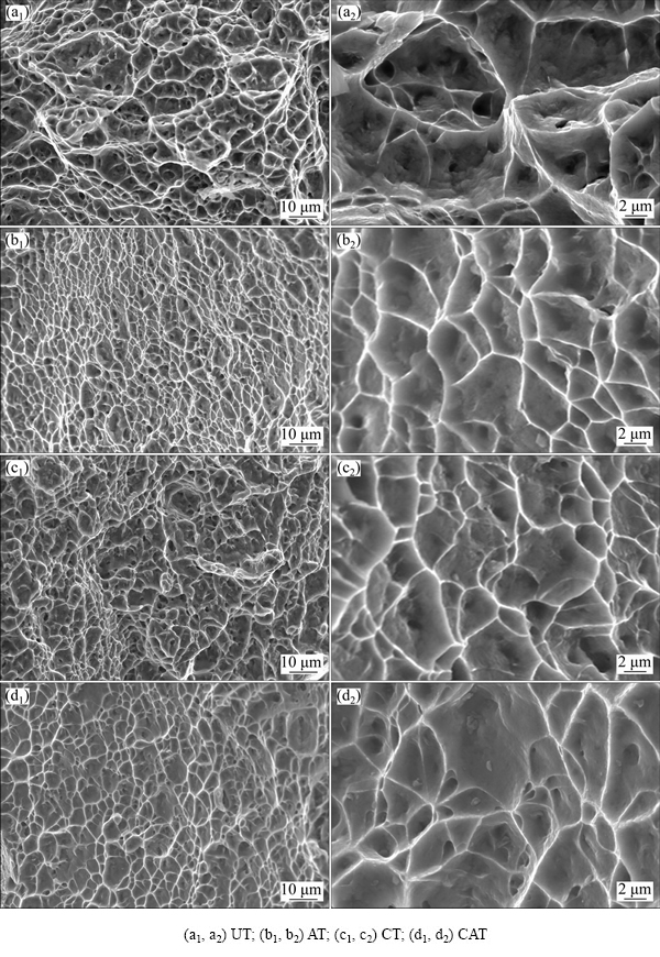
Fig. 7 SEM images of fracture surface for heat-treated and untreated samples
3.2 Tensile test and hardness results
The tensile test and Vickers hardness test results are shown in Figs. 6-8. The tensile strength, yield stress and elongation of the untreated sample are 982.7 MPa, 978.3 MPa and 10.2%, respectively. It can be seen that the tensile strength and yield stress values of the treated samples decrease slightly after heat treatments compared with the untreated ones.
In the cryogenic treatment procedure, two main factors, the cryogenic treatment temperature and the soaking time, affect the mechanical properties, phase transformation and formation of microstructure [9,17,18]. When cryogenic treatment is applied, with the decrease in the cryogenic treatment temperature, due to the reduction in the content of vanadium element, more �� phase transforms to meta-stable �� phase [1]. Also, the micro-stress values exceed the micro-yield stress values because of the low-temperature treatment applied, and the beginning of the formation of micro-cracks in the materials results in the reduced tensile properties of the material. Likewise, a long soaking time also leads to the formation of a similar microstructure. The dislocations formed in the metal increase the hardness of the material with increasing soaking time. But this situation is effective in cases where the soaking time is longer than 24 h [9]. Even though the effect of increasing the soaking time on the tensile properties is not known, considering the effects on the microstructure of increasing the soaking time, it can be said that the tensile strength will decrease. Although increasing soaking time and lowering cryogenic treatment temperature lead to the increased treatment costs and manufacturing time, they cannot increase the expected mechanical properties. Compared with previous studies, the obtained test results show that a temperature of -140 ��C and a 6 h cryogenic treatment cycle lead to the optimum values of the mechanical properties of the material [1,2,9].
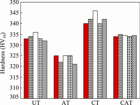
Fig. 8 Comparison of results of hardness tests on sample groups
During the cryogenic treatment, especially in alloys with different phases such as Ti-6Al-4V, ��+�� phase with different expansion coefficients is subjected to various stresses due to the temperature decrease [17]. These stresses create the force required to move the dislocations and facilitate the movement of dislocations such as vacancies and interstitial atoms. The dislocations interact with each other, causing micro-deformations to occur, and during the tensile tests these deformations start the formation of cracks and damage, reducing the tensile strength of the material [1]. However, this reduction is quite small here: it is less than 0.32% in the CT sample and about 2.2% in the CAT sample. Additionally, when the cryogenic process is applied, the elongation of the Ti-6Al-4V alloy decreases by a small amount (1%). However, this reduction does not affect the impact resistance of the material at a level that reduces the toughness of the material. In a previous study, the applied cryogenic treatment increased the plasticity and this increase was explained by the reduced �� phase in the material microstructure and decrease in the amount of dislocations, resulting in the increase in the elongation and plasticity of the Ti-6Al-4V alloy [1]. But in this study, the low cryogenic treatment temperature and short soaking time decrease the �� phase transformation.
As a result of aging treatment, the tensile strength of the material was decreased by approximately 2%. When the microstructure of the materials was analyzed, the content of �� phase increased due to the aging treatment while the plasticity and tensile strength of the alloys decreased. The content of �� phase decreased after treatment in the CT and CAT samples, and the tensile strength and elongation decreased in both types of samples.
In order to investigate the effect of different types of heat treatments on the tensile properties, the fracture surfaces of the tested samples were examined by SEM. The fracture surface morphologies of the samples are given in Fig. 7. The microstructure of annealed Ti-6Al-4V alloy consists of equiaxed dimpled structures dispersed throughout the fracture surface with other secondary particles. With the implementation of the cryogenic process, the dimple structure was made smaller and took a denser form. This form of cryogenic treatment induced a decrease in the plasticity of the material. Moreover, on the fracture surface of the aging-treated samples, the dimpled structure became narrow and the borders were more prominent. The aging and cryogenic treatments affect the dimpled structure of the CAT samples and the dimples expand with heat treatment.
In previous studies focused on heat treatment, aging treatment at 550 ��C decreased the hardness of Ti-6Al-4V alloy [1,2]. Aging treatment increased the �� phase in the material and this caused a decrease in the material��s hardness [2]. Five Vickers hardness values obtained for different measurements are given in Fig. 8 for all samples. The result of the present study was that aging treatment decreased the hardness by about 2%. The hardness values of the CAT samples and the untreated samples were evaluated as being approximately the same value, and according to this indication, it could be said that the cryogenic treatment followed by aging treatment had no influence on the hardness of the alloy. After the cryogenic treatment, the material��s hardness increased by about 2.2%. The reason for this increase in hardness was a change in the dislocation density in the microstructure. The incidence of stress simplified the dislocation movement and this caused a growth in the dislocation density and hardness of the material [1,9].
3.3 Low-energy impact test results
During the impact tests, as a result of the impactor hitting the samples, a compressive stress wave is formed. This stress wave advances through the thickness of samples based on the acoustic impedances of the constituent material in the plate and is partially reflected and partially conducted to the contact surfaces of the material. The intensity and signs (tensile and compression) of these conducted and reflected waves are the most important parameters that affect the impact performances of the samples and the formation of post-impact damage in them. In the present study, the effects of the heat treatment procedure on the impact damage mechanisms and impact resistance of Ti-6Al-4V alloy were examined and the efficiencies of the treated samples under impact loading were analyzed.
Before the low-energy impact tests, pre-experiments were applied to samples to determine the energy level to be used. The results showed that samples were penetrated at 80 J with the 60�� conical impactor nose geometry. Therefore, the samples were tested using three different impact energy levels of 80, 60 and 40 J. Energy, time, deflection and force data were obtained from impact tests to investigate the damage characteristic of the alloy and the effect of loading magnitude and impactor types. Energy�Ctime and force�Cdeflection curves were used to investigate the impact and damage formation history of different heat-treated samples. The impact characteristics of materials can be interpreted by looking at the force�Cdeflection diagrams. The forms of the force�Cdeflection curves are categorized into open and closed forms. Closed form curves are seen as a rebound case; the rebound decreases with increasing impact energy level, and if the energy level continues to increase, the curve changes from a closed rebound curve to an open penetrated or perforated curve.
The force�Cdeflection curves were the closed form, as shown in Figs. 9(a) and 10(a). The force is a compressive load during the impact test and the deflection is a result of displacement of the samples in the areas where the impact was applied. In these force�Cdeflection curves, the closed area is equal to the energy absorbed by the samples during the impact tests. The force�Cdeflection curves consist of three different characteristic regions. In the first region, the force increases up to the peak point of the maximum force Fmax; this region is called the bending stiffness and affects the impact resistance of the samples. The second region is an area of irregularities that occur because of the formation of cracks and failure modes in the samples. The last region is the rebound section; when this occurs, the force�Cdeflection diagram forms a closed shape. The force�Cdeflection curves of the four samples are given in Fig. 9(a). When the force�Cdeflection curves of four samples were examined according to this knowledge, it was seen that the force�Cdeflection curves of all samples had approximately the same characteristic. The curves increased to the peak load Fmax, a plateau occurred around Fmax, and then the curves decreased because of rebounding. But the bending stiffness of CAT sample was greater than those of the other samples and the biggest force Fmax was seen for CAT sample. If we consider Fmax as resistance to penetration, it can be said that CAT samples have greater strength than the other samples. CAT samples have the greatest impact resistance because of the effects of aging and cryogenic treatments on the microstructure and tensile and hardness properties.
In the energy�Ctime diagrams, two main parameters, the absorbed energy Ea and the rebound energy Er, are used to assess the results of the low-energy impact tests.
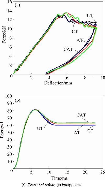
Fig. 9 Low-energy impact test diagrams for hemispherical impactor at impact energy of 80 J
The absorbed energy is transferred to the samples from the impactor during the tests and the rebound energy is retained in the impactor after the tests. In Fig. 9(b), the energy�Ctime curve reaches a peak point and then the energy starts to decrease until it reaches a constant value. The difference between the peak point and the constant energy level is named the rebound energy. The constant energy level is the energy absorbed by the samples. In this study, cryogenic treatment results in an increase in the impact resistance. However, the transformation of �� phase to meta-stable �� phase causes a decrease in the �� phase, which results in an increase in the hardness and the brittleness of the alloy. The increased hardness of the alloy leads to an increase in the impact resistance. Additionally, the rebound energy determined for CT samples is higher than those of other samples. Due to their high hardness, the CT and UT samples absorbed less energy than the CAT and AT samples. After the aging treatment, the hardness decreased and the proportion of the �� phase increased. Therefore, the energy absorption capability and toughness of the alloy increased. But cryogenic treatment followed by aging treatment increased the hardness by a small amount due to the increased proportion of �� phase, which led to an increase in the impact strength of the alloy. Because of their high toughness, the biggest energy absorption was seen in the CAT samples: 75% of 80 J was absorbed by the CT and UT samples, 76% by the AT samples, and 81% by the CAT samples.
During the impact tests, it was observed that the impact nose geometry and impact energy level obviously affected the impact damage behaviour and impact resistance of the material [10,11]. The blunt impactor nose geometries caused failure modes by plugging and the hemispherical and conical geometries penetrated the samples by increasing the compressive stress due to the nose angle and by pushing the material from the top face to the back face [10,11]. In this study, the effects of impactor nose geometry on the damage modes, damage area and absorbed energy were investigated. The force�Cdeflection and energy�Ctime curves obtained for untreated sample at impact energy of 80 J are shown in Fig. 10. In Fig. 10, all force�Cdeflection curves change as the impactor nose angle changes and all of the curves
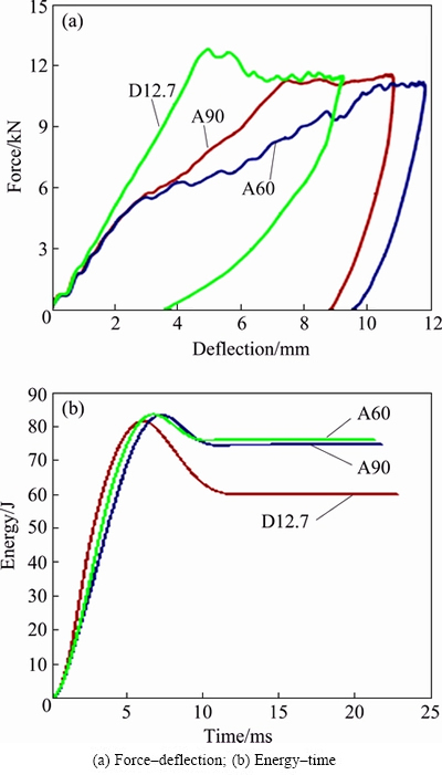
Fig. 10 Effect of impactor nose geometry on impact strength of untreated sample at impact energy of 80 J
have different impact loading characteristics. The conical geometries increase the compressive stress with decreasing impactor nose angle. For the hemispherical impactor geometry, on the force�Cdisplacement graph, the force shows a steady increase until it reaches the Fmax value, but for conical geometries, the curve shows irregularities before the force reaches the peak force Fmax because of the occurrence of fractures and cracks in the material��s surface. The irregularities of the curves increase as the impactor nose angle decreases, and these irregularities start at the first moment of impactor displacement in the application of the conical impactor nose geometry impact test. As can be seen in Fig. 10, it is also concluded that Fmax decreases with decreasing impactor nose angle and the curves expand with the increase of conical geometry. As a result, the rebound energy also decreases. Fmax reaches the greatest value for the hemispherical geometry because it is not exposed to penetration. If we recognize Fmax as resistance to penetration, it can be said that the impact resistance decreases with decreasing impactor nose angle. The decrease of the impactor nose angle reduces the rebound but increases the maximum impact energy and maximum displacement. The energy absorption of different impactor nose geometries is seen in Fig. 10(b). The lowest energy absorption is seen with the hemispherical impactor and the energy absorption increases as the impactor nose angle decreases. It was found that 78% of the impact energy of 80 J was absorbed by D12.7, 91% by A90, and 92% by A60.
3.4 Post-impact damaged zone and observation of damage modes
The impact test results showed that as the impactor advanced through the plate thickness, deformation occurred towards the sides, shear stress occurred in the thickness within the plane, and normal stress occurred. These shear and normal stresses caused the formation of cracks, failure mode and impact damages. Crack formation in samples usually occurred around the impact area or immediately below it and moved towards the far side of the impact centre. The damage occurred in a wider area on the top surface of the plate, while the damage on the bottom surface was smaller. The damaged area was used to analyze the impact characteristics and to compare the results. The damaged areas in the samples after each impact test are presented in Fig. 11. It could be seen from Fig. 11 that the damaged area increased with increase in the applied energy level. Even though full penetration was not seen in any groups of samples, the existence of damage was observed on both faces. The damaged areas obtained with the D12.7 impactor were compared among all sample groups at all impact energy levels. With cryogenic treatment, the area of damage decreased by about 22%, and with aging treatment, the area of damage decreased by about 26%. The smallest deformation area was seen in the CAT sample; after treatment, the damaged area decreased by about 30%. When the damaged areas were examined, it was seen that applying the heat treatment decreased the tensile stress by 1%-2% and reduced the damaged area by 22%-30%.
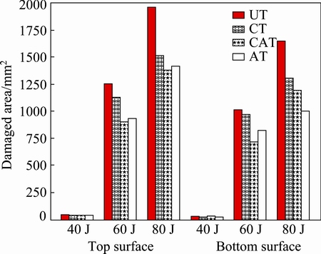
Fig. 11 Comparison of damaged areas applied with hemispherical geometry for different sample groups
The effect of the heat treatment procedure on damaged modes was investigated with the A90 impactor nose geometry and the comparison of the damaged areas of different samples is shown in the SEM images in Fig. 12. In the SEM image, the damaged areas of UT samples could be seen to be completely different from those of the other types of samples. The area of compressive damage of UT samples was limited and the branched surface was separated from the sample. Damaged areas of CT and CAT samples had similar characteristics and damage formation. In both samples, there was intense shear localization in the area of compressive damage and the crack formed by the impact branched. But in CAT samples, the area of compressive damage was larger than in CT samples and crack propagation spread over a large area. In AT samples, the crack formation was quite different from that in cryogenically treated samples. The damaged area in the AT samples was limited to a smaller area and small branched cracks were not seen due to the high toughness characteristic.
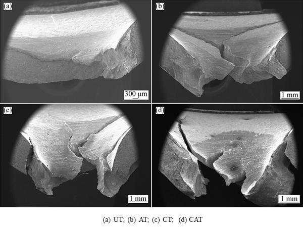
Fig. 12 SEM images of damaged areas of samples impacted by A90 impactor at impact energy of 80 J
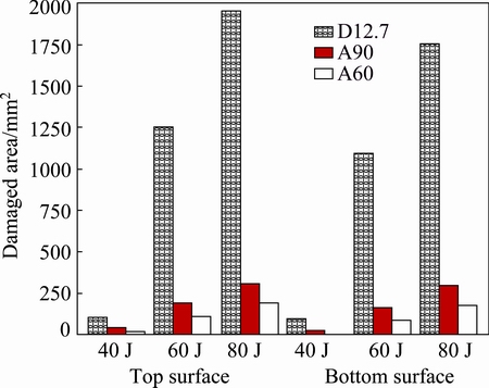
Fig. 13 Effect of impactor nose geometry on damage area of UT samples
The impact damaged area of UT samples for different nose geometries was determined, as shown in Fig. 13. Even though penetration was not seen with the hemispherical geometry, a crack occurred and the surface crack widened with spherical geometry, with the deformation area spreading over a wide area. With the A90 and A60 conical impactor geometries, the deformation area narrowed because the force cannot spread over the target material. Consequently, the damage characteristics changed completely with changes in the impactor nose geometry. When the effect of impactor nose geometry on the damaged area was investigated, it was seen that the area of damage caused by the D12.7 impactor was nine times larger than that caused by the A60 impactor. The difference between the damaged areas at the top and bottom with the conical geometries was great at a low impact energy level but decreased with increasing impact energy. When the damaged areas were evaluated at the macro level, the impact angle and impact energy were found to directly affect the occurrence of cracks, crack propagation, and the damaged areas on the top and bottom surfaces. The hemispherical impactor nose geometry caused large cracks on the top surface and a small deflection on the bottom surface, but the A90 and A60 nose geometries caused small damaged areas and large deflection.
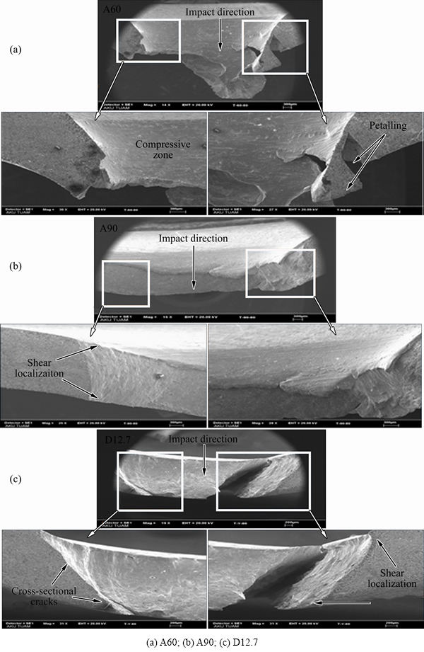
Fig. 14 SEM images of cross-sections of damaged areas of UT samples at impact energy of 80 J
The comparison of the effect of the impactor nose geometry on the damage modes is illustrated in Fig. 14. Each nose geometry caused different damage modes. In Refs. [19,20], there was frequent mention of plugging and petalling failure modes. Plugging-type failure occurred when samples were tested with blunt nose geometries and the impactor pushed a part of approximately the same size as the impactor diameter, whereas petalling occurred when greater stress was applied than the tensile strength in the contact area [19]. Petalling failure was seen with the A60 impactor nose geometry because of the impactor nose angle: the force impacted a narrow area and the fracture surfaces separated from each other and curved from the top surface to the bottom surface. At the same impact energy, the A90 geometry caused a small deflection and compressive zone, but the shear localization area became more obvious than that obtained with the A60 impactor. The damage mode caused by the D12.7 impactor was different from those caused by the conical geometries. Because the D12.7 impactor caused no plugging or petalling, only cracks occurred on the cross-section of the damaged area, as well as intense shear localization.
4 Conclusions
The low-energy impact behaviour and damage characteristics of Ti-6Al-4V alloy were investigated after cryogenic treatment (CT), aging treatment (AT), and cryogenic treatment followed by aging treatment (CAT) procedures. Impact tests were performed on heat-treated and untreated samples using different impactor nose geometries. After each test, the samples�� damage modes were calculated by considering the size of the deformation area. The test results showed that energy absorption increased and damaged areas decreased in all treated samples. The highest energy absorption and the smallest damaged area occurred in the CAT samples. The hardness of the material increased by 2.25% due to the cryogenic treatment, whereas it decreased by 2% as a result of the aging treatment. At the same time, the tensile strength of all the heat-treated samples decreased by a small amount. Also, the cryogenic and aging treatments affected the phase distribution. Cryogenic treatment decreased the �� phase content, aging treatment increased it. Additionally, it was seen that the damaged area and deflection were strongly dependent on the impactor nose geometry. The maximum deflection and the narrowest deformation area were seen with the 60�� conical nose geometry. The size of the damaged area increased with the increase in the impactor nose angle. Also, the greatest elastic deflection and rebounding were seen with the D12.7 impactor.
References
[1] GU Kai-xuan, ZHANG Hong, ZHAO Bing, WANG Jun-jie, ZHOU Yuan, LI Zhi-qiang. Effect of cryogenic treatment and aging treatment on the tensile properties and microstructure of Ti-6Al-4V alloy [J]. Mater Sci Eng A, 2013, 584: 170-176.
[2] GU Kai-xuan, WANG Jun-jie, ZHOU Yuan, ZHANG Hong, LI Zhi-qiang, ZHAO Bing. Effect of cryogenic treatment on the plastic property of Ti-6Al-4V titanium alloy [J]. Cryogenic Engineering, 2014, 1574: 42-47.
[3] VENKATESH B D, CHEN D L, BHOLE S D. Effect of heat treatment on mechanical properties of Ti-6Al-4V ELI alloy [J]. Mater Sci Eng A, 2009, 506: 117-124
[4] SINGH B B, SUKUMAR G, BHATTACHARJEE A, KUMAR K S, BHAT T B, GOGIA A K. Effect of heat treatment on ballistic impact behavior of Ti-6Al-4V against 7.62 mm deformable projectile [J]. Mater Des,2012, 36: 640-649.
[5] RICHARDS N L. Quantitative evaluation of fracture toughness- micro structural relationships in alpha-beta titanium alloy [J]. J Mater Eng Perform, 2004, 13: 218-225.
[6] RICHARDS N L. Prediction of crack deflection in titanium alloys with a platelet microstructure [J]. J Mater Eng Perform, 2005, 14: 91-98.
[7] DAI S J, WANG Y, CHEN F, YU X Q, ZHANG Y F. Influence of Zr content on microstructure and mechanical properties of implant Ti-35Nb-4Sn-6Mo-xZr alloys [J].Transactions of Nonferrous Metals Society of China, 2013,23(5): 1299-1303.
[8] MOHAN L D, RENGANARAYANAN S, KALANIDHI A. Cryogenic treatment to augment wear resistant of tool and die steel [J]. Cryog, 2001, 41: 149-155.
[9] GU K, WANG J, ZHOU Y. Effect of cryogenic treatment on wear resistance of Ti-6Al-4V alloy for biomedical applications [J]. Journal of the Mechanical Behavior of Biomedical Materials, 2014, 30: 131-139.
[10]  T, LANGSETH M, HOPPERSTAD O S, MALO K A. Perforation of 12 mm thick steel plates by 20 mm diameter projectiles with flat, hemispherical and conical noses part II: Numerical simulations [J]. Int J Impact Eng, 2002, 27: 37-64.
[11] BORVIK T, LANGSETH M, HOPPERSTAD O S, MALO K A. Perforation of 12 mm thick steel plates by 20 mm diameter projectiles with flat, hemispherical and conical noses part I: Experimental study [J]. Int J Impact Eng, 2002, 27: 19-35.
[12] CHEN X W, LI Q M. Perforation of a thick plate by rigid projectiles [J]. Int J Impact Eng, 2003, 28: 743-759.
[13] MITREVSKI T, MARSHALL I H, THOMSON R. The influence of impactor shape on the damage to composite laminates [J]. Comp Struct, 2006, 76: 116-122.
[14] SENTHIL K, IQBAL M A. Effect of projectile diameter on ballistic resistance and failure mechanism of single and layered aluminum plates [J]. Theor Appl Frac Mech, 2013, 66-67: 53-64.
[15] GUPTA N K, IQBAL M A, SEKHON G S. Effect of projectile nose shape, impact velocity and target thickness on the deformation behavior of layered plates [J]. Int J Impact Eng, 2008, 35: 37-60.
[16] GUPTA N K, IQBAL M A, SEKHON G S. Effect of projectile nose shape, impact velocity and target thickness on deformation behavior of aluminum plates [J]. Int J Solids Struct, 2007, 44: 3411-3439.
[17] AMINI K, AKHBARIZADEH A, JAVADPOUR S. Investigating the effect of holding duration on the microstructure of 1.2080 tool steel during the deep cryogenic heat treatment [J]. Vacuum, 2012, 86: 1534-1540.
[18] MEYER LW, KRUGER L, SOMMER K, HALLE T, HOCKAUF M. Dynamic strength and failure behavior of titanium alloy Ti6Al4V for a variation of heat treatments [J]. Mech Time-Dependent Mater, 2008, 12: 237-247.
[19] CORBETT G G,  S R, JOHNSON W. Impact loading of plates and shells by free-flying projectiles: A review [J]. Int J Impact Eng, 1996, 18: 141-230.
[20] REN Y, TAN C W, ZHANG J, WANG F C. Dynamic fracture of Ti-6Al-4V alloy in Taylor impact test [J]. Transactions of Nonferrous Metals Society of China, 2011, 21(2): 223-235.
N. YUMAK1, K. ASLANTAS1, Y. PEKBEY2
1. Department of Mechanical Engineering, University of Afyon Kocatepe, Afyon-03000, Turkey;
2. Department of Mechanical Engineering, University of Ege, -35030, Turkey
ժ Ҫ���о������ʱЧ������Ti-6Al-4V�Ͻ���ǿ�Ⱥ���ѧ���ܵ�Ӱ�졣��Ti-6Al-4V�Ͻ�ֱ�������䴦��(CT)��ʱЧ����(AT)�Լ��������ʱЧ����(CAT)���ò�ͬ������״(��Բ�Ρ�60���90����)�ij��ͷ�Ծ��ȴ�����δ���ȴ���Ti-6Al-4V��Ʒ���г��ʵ���Կ�����ͷ������״����Ʒ�������Ե�Ӱ�졣��������������ȴ�����Ʒ�����������Ӷ�����������͡������������������ӣ�CAT��Ʒ������ߵ�������������С�������������δ����������Ʒ���������Ρ����⣬���ͷ�ļ�����״����Ʒ�����������ƫ������������Ӱ�졣ʹ��60���dz��ͷ���г��ʵ�����Ʒ��������ƫ����(��)����С�����������Ʒ�ı����������ͷ�ǵ����������
�ؼ��ʣ�Ti-6Al-4V�Ͻ����䴦����ʱЧ���������ܳ��ʵ�飻������ˣ����ͷ������״
(Edited by Wei-ping CHEN)
Corresponding author: K. ASLANTAS; E-mail: aslantas@aku.edu.tr
DOI: 10.1016/S1003-6326(17)60058-X

