J. Cent. South Univ. Technol. (2007)01-0032-05
DOI: 10.1007/s11771-007-0007-2

Heating and melting mechanism of stainless steelmaking dust pellet in liquid slag
PENG Ji(彭 及)1, TANG Mo-tang(唐谟堂)1, PENG Bing(彭 兵)1, YU Di(余 笛)2,
J. A. KOZINSKI3, TANG Chao-bo(唐朝波)1
(1. School of Metallurgical Science and Engineering, Central South University, Changsha 410083, China;
2. School of Information Science and Engineering, Central South University, Changsha 410083, China;
Abstract: The heating and melting mechanisms of the pellets immersed in liquid slag were investigated, and the effect of the pellet heating and the melting conditions were studied. The results show that the dust component in the pellet is melted from the surface and no metallic elements are melted before the dust component, the time for the pellet completely melted is reduced as the iron powder content increases since the metallic iron has high thermal conductivity. These are four stages of heating and melting of pellet in liquid slag, they are the growth and melt of solid slag shell, penetration of liquid slag, dissolving of dust component and melting of reduced metals. The lifetime of the solid slag shell is in the range of 7-16 s and increasing the pre-heating temperature of the pellet and the slag temperature can shorten the slag shell lifetime. The time for the dust component in the pellet to be melted completely is in the range of 20-45 s and increasing the pre-heating temperature, especially in the range of 600-800 ℃, can obviously reduce the melting time. A higher slag temperature can also improve the pellet melting and the melting time is reduced by 10-15 s when the slag temperature is increased from 1 450 to 1 550 ℃. The pellet with higher content of iron powder is beneficial to the melting by improving the heat conductivity.
Key words: heating; melting; mechanism; stainless steelmaking dust; recycling
1 Introduction
Approximately 1%-2%(mass fraction) of the scrap charged into the smelting furnaces is converted into dust and then collected as particulate matter by the bag-house in stainless steelmaking operation[1]. This dust is considered as a by-product of steelmaking process. When stockpiled, the dust leaches heavy metals to the groundwater or rainwater in the concentrations that exceed the environmental guidelines, so it is assigned as a hazardous waste and banned from landfills by various government regulatory agencies[2]. In addition to being an environmental hazard, the dust is also an economical concern to stainless steel makers as it contains large amounts of valuable metals such as chromium and nickel[3-4]. Direct recycling of stainless steelmaking dust is a newly developed technology to recover the metals present in the dust and protect the environment[5]. It is a self-reduction and self-recycling remediation option and aims at recovering the metallic elements from the dust directly to the steel bath in the stainless steelmaking practice by forming the pellets of dust and carbon that are subsequently fed to the steelmaking furnace[6-7]. Under the thermal conditions that prevail in the furnace, the metals in the dust are reduced by carbon and recovered into the steel as the alloying elements of stainless steels. In order to do so, the characteristics of the dust were investigated as well as the isothermal and non-isothermal[8-12] kinetics models of the reduction were established. However, the processes of the pellet heating and melting in the liquid slag media play an important role in the direct recycling of stainless steelmaking dust. Therefore, it is necessary to get a better understanding of the mechanism of the processes and the influence of the operating conditions.
MERISSNER et al[13] developed a numerical model for the process of reduction and meltdown of ore-carbon pellets and CLEARY et al[14] introduced a Lagrangian simulation method(smoothed particle hydrodynamics) to simulate the behavior of pellets immersed in the liquid bath and the heat transfer. But it was found in our previous studies on direct recycling of stainless steelmaking dust that the processes of heating up and melting of the stainless steelmaking dust pellet in liquid slag were much more complicated[15]. Four stages could be approximately imagined after the pellets were immersed in the liquid slag medium[16-17].
This study focused on the experimental research to identify the above phenomena and their dependence on the pellet properties and melting conditions, as well as to collect data for setting up the model to simulate the pellet melting process. The experimental work was planned to find out the temperature field inside the pellet by means of temperature measurement at the pellet center and the movement of melting interface position by means of analyzing the images caught during the pellet immersion in liquid slag. The internal structure of the pellets and their variation during the heating and melting inside the liquid slag were also investigated.
2 Experimental
2.1 Raw and processed materials
The stainless steelmaking dust used in the experiment was taken from a stockpile and its composition is listed in Table 1. The dust was crushed in a ball miller for about 20 min and then screened to below 0.45 mm in order to be suitable for pelletization. The particles of carbon used as the reducing agent and dolomite used as the binder in the pellets were very fine. The composition of the formed pellets was 50%-80% dust, 15% carbon and 5% dolomite. The diameter of the formed pellets was about 13 mm and pure iron powders with content of 0, 15% and 30% were respectively added to the pellets instead of the dust. The synthetic slag with the composition of 45% CaO, 35% SiO2 and 20% Al2O3 was used in this experiment.
Table 1 Main composition of stainless steelmaking dust (Mass fraction, %)
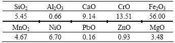
Al2O3 crucibles with diameter of 35 mm and height of 55 mm were used and the slag input was 40 g in each trial. The analysis of slag after experiment showed the composition of w(Al2O3)<25% and w(FeO)<5%.
2.2 Experimental procedure
Fig.1 shows the schematic diagram of the equipment. An alumina tube with a thermocouple was fixed at the center of the pellet. At a given slag temperature and with a certain pre-heating temperature, the pellet was immersed into the liquid slag bulk. The temperature of the pellet center was measured continuously during the experiment. The pellet was taken out in a given period, quenched down in the liquid nitrogen and then cut into two hemispheres and analyzed with the optical microscope and scanning electron microscope(SEM) to observe the particle morphology and electron probe micro-analysis(EPMA) to check the elemental distribution within the samples.
Two series of experiments were arranged for this study. Table 2 lists the arrangement of series one. The variables examined in the experiment included the mass fraction of iron powder in the pellet, pre-heating temperature of the pellet and slag temperature. Table 3
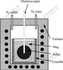
Fig.1 Schematic diagram of heating experiment
Table 2 Setup of experiments for series one
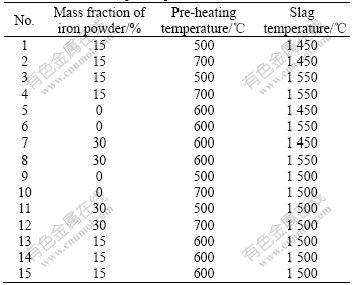
Table 3 Setup of experiments for series two
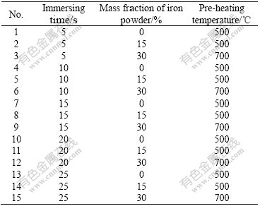
lists the arrangement of series two. Three groups of pellets with different mass fractions of iron powder and pre-heating temperatures were tested and the immersion time was in the range from 5 s to 25 s at the slag temperature of 1 550 ℃.
3 Results and discussion
3.1 Temperature measurements
Fig.2 shows the pellet center temperature in the different experimental trials. It can be seen that the temperature curves of pellet center rise after the pellet is immersed into slag, and then reach a certain temperature and then hotd at there until the pellet drops from the thermocouple. The plateau in temperature curves is in the range of 1 350 ℃ and 1 420 ℃. This temperature range is approximately the slag melting temperature. The results confirm the assumption that the dissolution of the dust component into liquid slag plays an important role in the pellet melting.
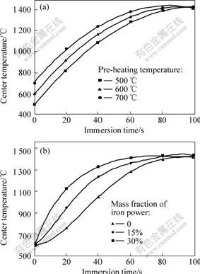
Fig.2 Temperature measurement of pellet center at different pre-heating temperature(a) and different mass fractions of iron power(b)
3.2 Solid slag shell
The morphology of the cut pellets after quenched in the liquid nitrogen gives some information about the formation, development and disappearance of solid slag shell in the pellets. The white ring on the sample indicates the solid slag shell and the variation of the shell thickness can be quantitatively determined. It is found that the solid shell forms as soon as the pellets are immersed in the liquid slag and it completely disappears in 7-16 s. Fig.3 shows the variation of the shell thickness after the pellet is immersed into liquid slag under different conditions. It can be seen from Fig.3 that the thickness of solid slag shell and time for the shell melting up depend on the pre-heating temperature of pellets and the slag temperature. Table 4 lists the data of influence of experimental conditions on the maximum solid slag shell thickness and time for complete melt of the shell.
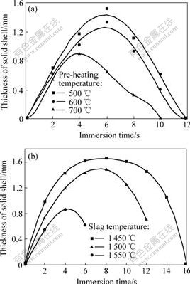
Fig.3 Effect of pre-heating temperature(a) and slag temperature(b) on thickness of solid slag shell
It is found that that the content of iron powder in the pellet has only limited influence on the slag shell formation, this is because slag shell formation around the pellet is related to pellet surface temperature while the iron powder content has a strong influence on the temperature of pellet center. The function of iron powder in pellet is to speed up the increase of the whole pellet temperature and reduce the temperature difference between the pellet surface and its center. Therefore, a high iron powder content in the pellet promotes the formation of slag solid shell and on the other hand accelerates the melt of the shell. It can be seen from Fig.3 and Table 4 that when the slag temperature is 1 550 ℃ the time for completely melting of the slag shell can be reduced from 14 s to 7 s with the increase of the pellet
Table 4 Effects of pre-heating temperature and slag temperature on maximum thickness of shell and time of shell melt
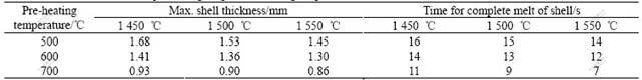
pre-heating temperature from 500 ℃ to 700 ℃, and on the other hand, the slag shell thickness is increased greatly and existing time of the slag shell is significantly prolonged with a low slag temperature and lower pellet pre-heating temperature.
3.3 Slag penetration
Penetration of the slag into the pellet occurs after the solid slag shell melts and disappears, which influences the heat transfer inside the pellet. This can be regarded as one of the essential characteristics of pellet melting in liquid slag. The results of EPMA, SEM and optical microscope observations indicate that the slag phase and its content are related to the melting progress. The area ratio of each phase, slag area (Ss) and dust area (Sd), in an observation frame by means of image analysis can be quantitatively determined. An index, the slag formation ratio (R), is defined to evaluate the slag penetration in the pellet as follows:
 (1)
(1)
The slag penetration into the pellet in different periods of time was continuously investigated from the pellet center to the surface along cut cross section of pellet by using slag formation ratio index. The average results under the experimental conditions of pre-heating at 600 ℃ and slag temperature of 1 500 ℃ are shown in Fig.4. The curves in the figures refer to the depth of slag penetration and slag formation ratio in different immersion times. The temperature measurement indicates that 80 s is required for the temperature of pellet center to reach the surface temperature which is the melting temperature of the slag. So, the penetrated slag will freeze since the temperature inside the pellet is still lower than its melting temperature. The results show that the slag penetration takes place rapidly as soon as the solid slag shell is completely vanished and the slag rapidly penetrates into the pellet center.
3.4 Pellet melting
Following the penetration of the slag is pellet melting. Pellet melting can be regarded as the movement of the liquid-solid interface from the pellet surface to the center. It is obvious that the structure is changed along the pellet radius after being immersed in the liquid slag. Fig.5 shows the reduction of the solid core size as a function of immersion time and mass fraction of iron
powder in the pellet under the experimental conditions of pre-heating temperature 600 ℃ and slag temperature 1 500 ℃. The interface movement from the pellet surface to its center can be explained by the contraction of solid core.
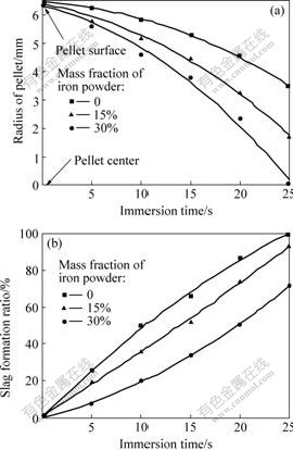
Fig.4 Radius of pellet(a) and slag formation ratio(b) vs immersion time
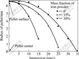
Fig.5 Change of solid core radius during pellet melting
4 Conclusions
1) A solid slag shell is formed and grows around the pellet when it is immersed in liquid slag. Then, the shell melts and the liquid slag penetrates into the pellet. After that, the pellet melts and the solid-liquid interface moves from the surface of the pellet to its center.
2) Under the experimental conditions of this study, the lifetime of the solid slag shell is in the range of 7-16 s and increasing the pre-heating temperature of the pellet and slag temperature can shorten the slag shell lifetime. The time for the dust component in the pellet to be melted down completely is in the range of 20-45 s and increasing the pre-heating temperature can obviously reduce the melting time. A higher slag temperature can also improve the pellet melting and the melting time is reduced by 10-15 s when the slag temperature is increased from 1 450 ℃ to 1 550 ℃.
3) The iron metal powders added to the pellet works on the heating and melting of stainless steelmaking dust pellets in liquid slag. The pellet with higher iron powder content is beneficial to the melting by improving heat conductivity.
References
[1] ZUNKEL D. What to do with your EAF dust[J]. Steel Times International, 1996, 20(4): 46-50.
[2] US Environmental Protection Agency. Federal Register, 56, 41164,.Land disposal restriction for electric arc furnace dust[S]. 1991-08- 19
[3] CYRO T, LUIZ C F, DENER M D S, et al. Recovery of Cr, Ni and Fe from dust generated in stainless steelmaking[J]. Transactions of the Institutions of Mining and Metallurgy, Section C: Mineral Processing and Extractive Metallurgy, 2005, 114(11): 201-206
[4] NOLASCO S P J, ROMANO E D C, BREDA M M, et al. Bench scale study of the chromium and nickel recovery from dusts and sludges generated in stainless steelmaking[C]// Proceedings of TMS 2005 Annual Meeting. California: Mineral, Metallurgical and Materials Society of TMS, 2005: 989-995.
[5] LOBEL J, PENG B, BOURASSA M, et al. Pilot-scale direct recycling of flue dust generated in electric stainless steelmaking[J]. Iron and Steelmaker, 2000, 27(1): 41-45.
[6] PENG Bing, PENG Ji, ZHANG Chuan-fu, et al. Thermodynamics calculation on the oxidation and sulfur removal ability of slag in EAF dust pellet reduction process [J]. Journal of Central South University of Technology, 2001, 8(1): 64-68.
[7] PENG Bing, PENG Ji, KOZINSKI J A, et al. Thermodynamic calculation on the smelting slag of direct recycling of electric arc furnace stainless steelmaking dust[J]. Journal of Central South University of Technology, 2003, 10(1): 20-26.
[8] SOUZA N D, KOZINSKI J A, SZPUNAR J A. EAF stainless steel dust, characteristics and potential metal immobilization by thermal treatment[C]// International Symposium on Resource Conservation and Environmental Technology in the Metallurgical Industry. Alberta: Metallurgical Society of CIM, 1998.
[9] PENG Ji, PENG Bing, YU Di, et al. Thermo-analytical study of stainless steelmaking dust [J]. Journal of Central South University of Technology, 2003, 10(4): 301-306.
[10] PENG Ji, PENG Bing, YU Di, et al. Kinetics of isothermal reduction of stainless steelmaking dust pellets[J]. Trans Nonferrous Met Soc China, 2004, 14(3): 593-598.
[11] ZHANG Chuan-fu, PENG Bing, PENG Ji, et al. Electric arc furnace dust non-isothermal reduction kinetics[J]. Transactions of Nonferrous Metals, 2000, 10(4): 524-530.
[12] PENG B, LOBEL J, KOZINSKI J A, et al. Non-isothermal reduction kinetics of EAF dust-based pellets[J]. CIM Bulletin, 2001, 94(1049): 64-70.
[13] MERISSNER S, KOBAYASHI I, TANIGAKI Y, et al. Reduction and melting model of carbon composite ore pellets[J]. Ironmaking and Steelmaking, 2003, 30(2): 170-176.
[14] CLEARY P W, STOKES N, PRAKASH M, et al. Simulation of reactive pellets in a pyrometallurgical bath using SPH[C]// Proceedings of the Minerals, TMS Annual Meeting. San Francisco, 2005: 647-654
[15] PENG Bing, PENG Ji, YU Di. Modeling of thermal conductivity of stainless-steelmaking dust pellets[J]. Trans Nonferrous Met China, 2004, 14(1): 184-189.
[16] DING Y L, WARNER N A, MERCHANT A J. Mathematical modeling of the reduction of carbon-chromite composite pellets[J]. Scandinavian Journal of Metallurgy, 1997, 26(1): 1-8.
[17] AKIYAMA T, OHTA H, TAKAHASHI R, et al. Measurement and modeling of thermal conductivity for dense iron oxide and porous iron ore agglomerates in stepwise reduction[J]. The Iron and Steel Institute of Japan International, 1992, 32(7): 829-837.
(Edited by CHEN Wei-ping)
Foundation item: Project(50274073) supported by the National Natural Science Foundation of China; project(Metallurgy 2003, CRDPJ 210038) supported by Natural Sciences and Engineering Research Council of Canada
Received date: 2006-05-25; Accepted date: 2006-07-18
Corresponding author: PENG Ji, Associate professor; Tel: +86-731-8821505; E-mail: zhubing@hnu.cn

