Trans. Nonferrous Met. Soc. China 25(2015) 405-411
Interfacial morphology evolution in directionally solidified Al-1.5%Cu alloy
Min QU1,2, Lin LIU2, Yan CUI1, Feng-bin LIU1
1. School of Mechanical and Materials Engineering, North China University of Technology, Beijing 100144, China;
2. State Key laboratory of Solidification Processing, Northwestern Polytechnical University, Xi��an 710072, China
Received 5 June 2014; accepted 9 October 2014
Abstract: The solid-liquid interfacial morphology evolution was investigated in directional solidification (DS) of Al-1.5%Cu alloy (mass fraction). The results show that the solidified microstructural evolution is gradual other than sharp, and the microstructure patterns are interesting and diversiform at the pulling rate ranging from 30 mm/s to 1500 mm/s. Indeed, dendrite to cell transition follows this sequence: dendrites��banded cellular dendrites��elongated cells and part of dendrites��main elongated cells and little dendrites. Moreover, the present microstructure is not normal microstructure as we saw before. Further, according to the experimental phenomenon, the dendrite to cell transition was studied theoretically. Dendrite tip shape is an important parameter to characterize the dendrite to cell transition. As the dendrite to cell transition is far from equilibrium solidification, non-equilibrium solidification is taken into consideration in calculation. Finally, it is speculated that the dendrite to cell transition would occur at the minimum tip radius.
Key words: Al-Cu alloy; dendrite to cell transition; directional solidification; pulling rate; interface morphology
1 Introduction
When a binary alloy is directionally solidified, a rich variety of transitions about pattern and microstructure are revealed [1,2]. As the pulling rate (velocity, v) is increased from zero, the planar solid-liquid interface becomes unstable to spatially periodic cells. When the velocity is increased further, there occurs a cellular to dendritic transition [3], and finally at a high velocity, these structures fade away as velocity approaches the ��absolute stability limit�� where the planar interface regains stability [4,5].
Up to now, transition from a planar to a non-planar interface at a low velocity and that from a non-planar to a planar interface at a high velocity have been well established [6,7], and these transitions have been shown to be sharp, so that they can be described by specific relationships among the velocity (v), thermal gradient ahead of the solid�Cliquid interface (G) and the alloy composition (C0). Moreover, the transition from cellular to dendritic microstructure at low velocity has been fully established, and early attempts assumed the transitions to be sharp and proposed criteria for cell to dendrite transition in terms of experimental variables G, v and C0. In particular, the former two parameters can be controlled independently while using a Bridgman- Stockbarger type directional solidification furnace [8,9]. GEORGELIN and POCHEAU [10] made important progress on the cell�Cdendrite transition (CDT). They got the conclusion that the start of the transition is considered when the largest cell spacing in an array just exhibits sidewise instability, and the transition is complete when the smallest cell spacing in the array forms side branches, so that all cells in an array have transformed into dendrites.
TRIVEDI et al [11,12] have employed SCN-camphor alloy to observe the CDT in directional solidification. They showed that the transition is gradual and occurs over a range of experimental conditions. Besides, they concluded the several transition phenomena, which are related to the sample thickness (d) and the primary spacing (��1): in the case of d >��1, only a single layer of cells or dendrites forms, the instability may first develop in the vertical direction rather than in the lateral direction. However, when d<��1, the onset of sidewise instabilities is achieved. Thus, it comes to the conclusion that the CDT is diffuse and gradual rather than sharp.
In contrast, the transition from dendritic to cellular interface at high velocity has not been accurately characterized. As the dendrite-cell transition (DCT) is hard to obtain experimentally, ASTA et al [13], CHEN et al [14] and TRIVEDI and KURZ [15] made important progress and finally concluded that both of the natures of DCT at high velocity and CDT at low velocity are the same from the perspective of physical mechanism. However, in some publications, it has been argued that the transition at high velocity is sharp and the range of pulling rate is narrow. From these viewpoints, the aim of this work is to research DCT transition, and to know whether the transition is sharp or gradual in experiment, and then to elucidate the transition phenomenon and perfect the DCT theory.
2 Experimental
In the present work, Al-1.5%Cu alloy was prepared from 99.99% Al and Al-Cu intermediate alloys with Cu content of 51.87% in an induction furnace. The specimen was cut to 3.5 mm in diameter and 150 mm in length. The Al-1.5%Cu alloy was solidified in a vertical directional solidification apparatus as shown in Fig. 1. The Bridgman type (B-type) furnace was heated with resistance wire, and the temperature accuracy of the furnace was controlled to be ��0.1 K with B-type Pt/Pt-13%Rh thermocouple track recorded. The directional solidification experiment was carried out in a B-type furnace made of a cold zone at the bottom and a hot zone at the top that imposed a thermal gradient of about 13 K/mm in the adiabatic area inserted between them. After withdrawn a predetermined distance, the specimen was quenched in water with a pneumatic plant which could avoid the delay of quenching. Upward solidification was achieved by downward pulling of the crucible into the water at pulling rate ranging from 30 to 1500 mm/s. The sample obtained was sectioned to be parallel and perpendicular to the solidification direction, mounted in epoxy, polished and etched with a mixture of HNO3, HCl and H2O. The sectioned microstructure was observed with a Lecia DM4000 optical microscope.
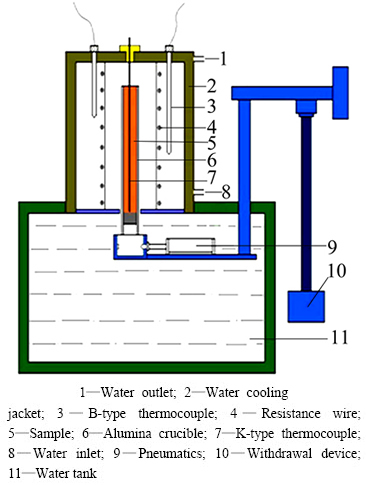
Fig. 1 Sketch of Bridgman resistance heating directional solidification apparatus
3 Results
The solid-liquid interfaces are shown in Fig. 2. As shown in Fig. 2(a), the solid-liquid interface is the mixed cellular and dendritic morphology (Longitudinal microstructures) when the pulling rate is 30 mm/s. It is seen that columnar cells arrange orderly, a few secondary dendrites appear near the interface, but they are cells as far from the interface. As the velocity increases to 100 mm/s, it is evolved to typical dendritic interface. It is clear that the interface becomes cellular dendrite when the pulling rate increases from 300 to 600 mm/s. As shown in Figs. 2(c) and (d), columnar cells are shortened and refined evidently in this range. The dendrites are obvious only at the quenched interface with the velocity increasing to 1000 mm/s in Fig. 2(e). However, the interface morphology is mainly cellular in the area far from the interface. With the pulling rate increasing, the interface morphology changes from mixed cells and dendrites to main dendrites and then to main cells. From Fig. 2, it is concluded that the interface morphology is evolved from the mixed cells and dendrites to dendrites and then to the mixed cells and dendrites in a wide pulling rate range. In order to know how the interfacial morphology evolves from cell to dendrite and from dendrite to cell in Al-1.5%Cu alloy, we researched the cross-section microstructure further.
Figure 3 clearly shows the microstructure evolution of transverse section of Al-1.5%Cu alloy in a wide range of pulling rates which are from 30 to 1500 mm/s. The microstructure is typical cells when the velocity is 30 mm/s in Fig. 3(a); however, the morphology is dendritic in the quenching section in Fig. 2(a) that is the longitudinal section corresponding to Fig. 3(a). As the pulling rate increases, the microstructure becomes the elongated cellular dendrites in Fig. 3(b). When the pulling rate increases to 100 mm/s, the morphology is not cells any more. At the same time, some of the cross-structures of dendrites appear, but they have not grown sufficiently yet, and they are just half or quarter cross-structures of the dendrites. Strictly speaking, the morphology is dendritic. Corresponding to the longitudinal section in Fig. 2(b), the dendritic interface is more obvious. As the pulling rate increases to 300 mm/s continuously, the shape of dendrite changes and the cross-structure degenerates. The microstructure evolves from dendrites to banded cellular dendrites gradually although the dendrites have not grown fully as seen in Fig. 3(d). The banded cellular dendrites are lined uniformly and regularly, meanwhile, they are refined obviously. The banded cellular dendrites are shortened constantly from Fig. 3(d) to Fig. 3(e). In Fig. 3(e), the microstructure is elongated cells instead of quadrate cells. Moreover, the elongated cells are refined and lined closely. Due to the shortening banded microstructure, some of the potential dendrite branches appear. By the extrusion of elongated cells, the dendrites do not develop and just part of them transform from cells to initial dendrites. Thus, it is mixed microstructure of elongated cells and part of dendrites in Fig. 3(e). When the pulling rate reaches 1500 mm/s, the dendrites gradually evolve into elongated cells during the time when most of dendritic cross-structures have been degraded in Fig. 3(f). However, some of cross-structures of a little dendrites still exist. Hence, the microstructures are still mixed microstructures of both elongated cells and dendrites. The difference only lies in that the elongated cells are the dominant part, and the microstructure is finer and arranges more closely.
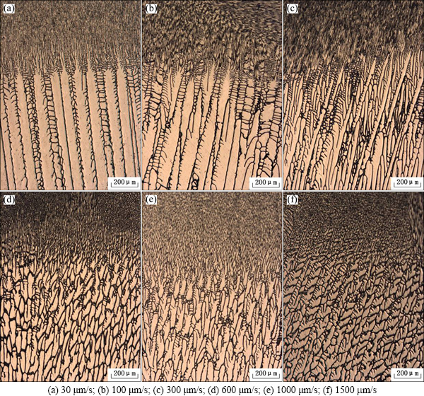
Fig. 2 Solid-liquid interfacial morphologies (Longitudinal microstructures) of Al-1.5%Cu alloys at different pulling rates during directional solidification
In conclusion, the patterns of solidification microstructure are diverse in Al-1.5%Cu alloy. The way of solidified microstructure evolution is as follows: it undergoes a transition from typical hexagonal cells to elongated cellular dendrites first, and then to dendrites at lower pulling rate. With increasing the velocity, the solidification microstructure transforms from dendrites to banded cellular dendrites. It evolves from banded cellular dendrites to elongated cells and part of dendrites conversely when the pulling rate reaches 300 mm/s. With further increase of the velocity, the fully developed dendrites do not change into elongated cells gradually, and the solidification microstructure is a mixture with more elongated cells and less dendrites. According to solidification microstructure evolution of Al-1.5%Cu alloy, we can speculate that the solidification microstructure can transform from elongated cells and dendrites to slender cells gradually with increasing pulling rate. Unfortunately, due to the limitation of other conditions, only the mixed microstructure was obtained and the slender cells cannot be obtained.
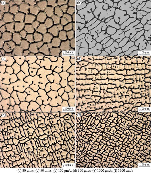
Fig. 3 Transverse microstructures of Al-1.5%Cu alloy at different pulling rates
4 Discussion
According to the velocity of CDT in the directional solidification in Eq. (1), we first calculate the critical transition velocity from cell to dendrite of Al-1.5%Cu alloy, and obtain the critical transition velocity vcd=9.3 ��m/s, which deviates from experimental result at v=30 ��m/s. Although the transition model of cell to dendrite is considerably mature, there is still a deviation between theoretical and experimental results. Moreover, since the transition requires a high degree of solidification parameters and alloy properties, it is very hard to get the dendrite to cell transition phenomenon. Unfortunately, there is a gap in dendrite to cell transitional theoretical model in the directional solidification.
 (1)
(1)
where GL is the thermal gradient; DL is the liquid diffusion coefficient; ��T0 is the effective solidification interval; k is the equilibrium partition coefficient; m is the liquidus slop; C0 is the initial composition of alloy.
As the lack of theory, we study the factors that can affect the transition from dendrite to cell and summarize the following several factors.
1) Thermal gradient. According to the stability of high gradient theory, the interface could keep absolute stability of planar interface morphology. The above mixed microstructure we get may be due to the relatively high temperature gradient. Unfortunately, the thermal gradient is not high enough, so, we only get mixed microstructure of dendrites and cells in the present study.
2) Pulling rate. Pulling rate plays an important role in interface morphology evolution. With the increase of the velocity, the interface morphology would undergo the process of planar��cellular��dendritic��cellular��planar interface. Moreover, the change of pulling rate can induce solute redistribution, then the solute concentration of solidification interface front changes, which can also cause the concentration field and temperature field of interface front to change. Hence, the solidification interface front comes into diverse morphologies. It is reported that the range of pulling rate of cells at high rate is far less than that of cells at low rate, which leads to that the cells at high rate are hard to reach. In this study, we only get the mixed microstructure probably because the pulling rate is not large enough.
3) Interface energy. At low velocity, interface stability is greatly influenced by thermal gradient and little influenced by interfacial energy. However, when the velocity is higher, the effect of thermal gradient can be neglected, nevertheless, the role of interfacial energy is great. As is known to all, interface energy can reduce interface area. Dendritic interface is more uneven than cellular interface, so dendritic interface area is larger than that of cellular interface. In the mixed cellular and dendritic microstructure, interface area is reduced due to the transition from some dendrites to cells, which cause the Gibbs free energy of system to reduce, thereby interface is more stable. Consequently, at high velocity, interface energy can promote interface stability.
The above three factors directly affect the dendrite to cell transition. In addition, dendrite tip radius is an important parameter to characterize the dendrite to cell transition because it reflects the transition of interface morphology directly [15]. Therefore, in dendrite to cell transition, we should not only consider the original cause of interfacial evolution which is interface stability as a starting point, but also take the effect of solidification parameters into consideration. Only combining all the factors, can we study the transition sufficiently and get more convincing conclusion.
The dendrite to cell transition is far from equilibrium solidification and comes into non- equilibrium solidification [16], thus we should take the non-equilibrium effect into consideration to calculate tip radius.
In non-equilibrium solidification, liquidus slope, equilibrium solute distribution coefficient, the liquid concentration at dendrite tip and so on are all changed. According to Aziz model [17,18], non-equilibrium solute distribution coefficient is a function of velocity, which is
 (2)
(2)
where a0 is a length scale related to the interatomic distance and is estimated to between 0.5 and 5 nm at D/a0 of 400 and 40 cm/s, respectively.
Effective liquidus slope is given by
 (3)
(3)
The liquid composition in non-equilibrium solidification is
 (4)
(4)
where  is Ivantsov function. For a needle crystal corresponding to a paraboloid of revolution is given by
 (5)
(5)
where is the exponential integral function defined by
 (6)
(6)
where P is the solute P��clet number, and it is the ratio of a characteristic dimension R of the system to the solute diffusion distance 2D/v, which can be written as
 (7)
(7)
According to Eqs. (2)-(7) and Kgt model [16], the result is shown in Fig. 4. The basic conceptions for the transition from cell to dendrite at low velocity are also fit for the transition from dendrite to cell at high velocity. Thus, we can speculate the dendrite to cell transition at high velocity according to the reverse transition at low velocity. Tip radius decreases fast as the pulling rate increases; however, in dendritic part, it decreases more slowly than that in cellular part, and there appears an inflexion at the tip radius. Namely, it is cell to dendrite transition point, as seen in Fig. 4. After we analyze the experimental results, the theoretical results coincide well with experiment if we ignore the experimental error. So, we could forecast the dendrite to cell transition with theoretical calculation.
In Fig. 4, with the increase of pulling rate, the dendrite is refined and dendrite tip radius reduces gradually. As the velocity increases further, the solute cannot diffuse fully, thus, it enriches at the dendrite tip which promotes the tip increase rapidly. However, due to the concentration gradient existing in the liquid near the secondary dendrite arm, the solute flows to secondary dendrite arm that is near the tip and makes the secondary dendrite arm at the tip melt, which lead to increasing the tip radius. It is worth noting that the disappearance of the secondary dendrite arm is the beginning of the dendrite to cell transition. Thus, it comes into another turning point of tip radius at high velocity. The shape of the tip cannot be described as parabolic shape any more. Nevertheless, it gradually becomes a rounded tip. According to the above analyses, combining the cell to dendrite transition occurring at the turning point in the left part of Fig. 4, we could consider that the dendrite to cell transition also occurs at the turning point in the lower right corner of Fig. 4. Namely,  corresponding to the minimum tip radius, is the transition velocity from dendrite to cell in directional solidification.
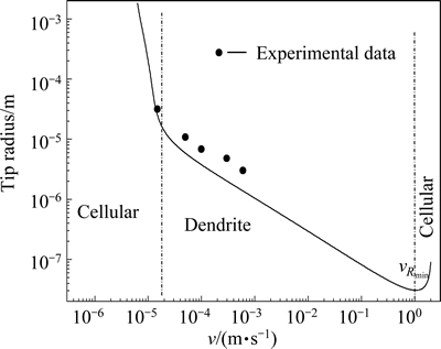
Fig. 4 Tip radius as function of pulling rate
5 Conclusions
1) The transition from dendrite to the mixed microstructure of dendrite and cellular is found in near rapid directional solidification of Al-1.5%Cu alloy. The patterns of solidification microstructure are diverse in the process. The transition process follows the sequence: dendrites��banded cellular dendrites��elongated cells and part of dendrites��main elongated cells and little dendrites.
2) Dendrite to cell transition of Al-1.5%Cu at high pulling rate occurs at the minimum tip radius.
References
[1] LIU K M, JIANG Z Y, ZHAO J W, ZOU J, CHEN Z B, LU D P. Effect of directional solidification rate on the microstructure and properties of deformation-processed Cu-7Cr-0.1Ag in situ composites [J]. Journal of Alloys and Compounds, 2014, 612: 221-226.
[2] MILLER J D, POLLOCK T M. Stability of dendrite growth during directional solidification in the presence of a non-axial thermal field [J]. Acta Materialia, 2014, 78: 23-36.
[3] DU D F, HOU L, GAGNOUD A, REN Z M, FAUTRELLE Y, CAO G H, LI X. Effect of an axial high magnetic field on Sn dendrite morphology of Pb-Sn alloys during directional solidification[J]. Journal of Alloys and Compounds, 2014, 588: 190-198.
[4] KURZ W, FISHER D J. Dendrite growth at the limit of stability: Tip radius and spacing [J]. Acta Metallurgica, 1981, 29: 11-20.
[5] MULLINS W W, SEKERKA R F. Stability of a planar interface during solidification of a dilute binary alloy [J]. Journal of Applied Physics, 1964, 35: 444-451.
[6] MA Y W, PLAPP M. Phase-field simulations and geometrical characterization of cellular solidification front [J]. Journal of Crystal Growth, 2014, 385: 140-147.
[7] LIMA M, KURZ W. Massive transformation and absolute stability [J]. Metallurgical and Materials Transactions A, 2002, 33(8): 2337-2345.
[8] PALIWAL M, JUNG I. The evolution of the growth morphology in Mg-Al alloys depending on the cooling rate during solidification [J]. Acta Materialia, 2013, 61: 4848-4860.
[9] YU H L, LI J J, LIN X, WANG L L, HUANG W D. Anomalous overgrowth of converging dendrites during directional solidification [J]. Journal of Crystal Growth, 2014, 402: 210-214.
[10] GEORGELIN M, POCHEAU A. Onset of sidebranching in directional solidification [J]. Physics Review E, 1998, 57: 3189-3203.
[11] TRIVEDI R, SHEN Y, LIU S. Cellular-to-dendritic transition during the directional solidification of binary alloys [J]. Metallurgical and Materials Transactions A, 2003, 34: 395-401.
[12] TENG J, LIU S, TRIVEDI R. Onset of sidewise instability and cell-dendrite transition in directional solidification [J]. Acta Materialia, 2009, 57: 3497-3508.
[13] ASTA M, BECKERMANN C, KARMA A, KURZ W, NAPOLITANO R, PLAPP M, PURDY G, RAPPAZ M, TRIVEDI R. Solidification microstructures and solid-state parallels: Recent developments, future directions [J]. Acta Materialia, 2009, 57: 941-971.
[14] CHEN Y, BILLIA B, LI D Z, NGUYEN-THI H, XIAO N M, BOGNO A. Tip-splitting instability and transition to seaweed growth during alloy solidification in anisotropically preferred growth direction [J]. Acta Materialia, 2014, 66: 219-231.
[15] TRIVEDI R, KURZ W. Dendritic growth [J]. International Materials Reviews, 1994, 39(2): 49-73.
[16] KURZ W, GIOVANOLA B, TRIVEDI R. Theory of microstructural development during rapid solidification [J]. Acta Metallurgica, 1986, 34: 823-830.
[17] AZIZ M J. Model for solute redistribution during rapid solidification [J]. Journal of Applied Physics, 1982, 53: 1158-1168.
[18] AZIZ M J. Interface attachment kinetics in alloy solidification [J]. Metallurgical and Materials Transactions A, 1996, 27: 671-686.
Al-1.5%Cu�Ͻ������̽�����̬�ݻ�
�� ��1,2���� ��2���� ��1�������1
1. ������ҵ��ѧ ��е����Ϲ���ѧԺ������ 100144��
2. ������ҵ��ѧ ���̼��������ص�ʵ���ң����� 710072
ժ Ҫ�����ö������̷����о�Al-1.5%Cu�Ͻ�֦��-����ת�������̬�ݻ���������������������ݻ����ɲ�ͬ�� ������֯�ݻ������еģ��ڳ�������Ϊ30~1500 mm/s�ķ�Χ�ڣ�������֯���ֶ�������֦��-����ת��������£�֦����������״֦����ϸ���Ͱ�����֦���Ļ����֯��ϸ���Ͱ���ռ�����İ�֦�����֯��������������һ�������۷����о�֦��-����ת�䡣֦�������״��֦��-����ת�����Ҫ����������֦��-����ת��ƫ��ƽ�����̣���ˣ��ڼ�������п��Ƿ�ƽ�����̣��õ�֦��-����ת�䷢���ڼ�˰뾶��С����
�ؼ��ʣ�Al-Cu�Ͻ�֦��-����ת�䣻�������̣��������ʣ�������̬
(Edited by Wei-ping CHEN)
Foundation item: Project (SKLSP201418) supported by the Fund of the State Key Laboratory of Solidification Processing in North China University of Technology, China; Projects (51171151, 51331005) supported by the National Natural Science Foundation of China
Corresponding author: Min QU; Tel: +86-10-88803012; E-mail: qmxm021@163.com
DOI: 10.1016/S1003-6326(15)63617-2

