
Formation mechanism of external finned tubes by extrusion-plough method
TANG Yong(汤 勇), LU Long-sheng(陆龙生), PAN Min-qing(潘敏强),
LIU Xiao-kang(刘小康), LIU Xiao-qing(刘晓晴)
College of Mechanical Engineering, South China University of Technology, Guangzhou 510640, China
Received 20 April 2006; accepted 30 June 2006
Abstract: The formation mechanism of bulge on the work’s surface during the extrusion process was analyzed. The bulge’s size and the reasons for abscission were studied. The results show that the abscission of bulge from works is resulted from the integrated actions of pressure and friction between the plough tool and works. During the extrusion-plough process, it is noticed that four kinds of fins are appeared, which are gestation fin, multi-dimensional fin, tumor and overlap fin, when using different machining parameters. And multi-dimensional fin which has high heat transmission efficiency is a kind of complicated fin with cockscomb-like 3D substructure fin on the tip of 3D macrostructure fin. Based on the studies of those four kinds of fins, the conditions of their formation are concluded, as well as the formation mechanism is obtained.
Key words: multi-dimensional fin tube; surface functional structure; formation mechanism; extrusion-plough
1 Introduction
The advanced heat-transmission and energy-saving technologies can provide an effective way to reduce the energy consumption and enhance energy utilization, so it has been widely used in electronics, architecture, dynamical machine, energy chemical industry, and so on[1]. Fin tube whose quality can greatly influence the effects is a critical part for heat transmission and energy-saving. Since 1950’s, many researchers studied the heat transmission property of smooth tube[2], and found that the heat transmission property and energy-saving ability can be enhanced by improving the tube’s material, optimizing tube’s layout, strengthening the tube’s application environment and bettering fin’s structure. HE et al[3-7] indicated that improving the tube’s surface structure was the most effective way. The very structure can strengthen the heat transmission ability, thus is called surface heat functional structure. The commonly used surface heat functional structure on fin tubes is inserting or machining 2D/3D fins. Based on the combination state of fins and the base, the fin tube can be classified as integral fin tube and non-integral tube. The integral kind gradually replaces the non-integral kind, just because the former creates no contacting heat resistance and has better resistance to heat fatigue. Meanwhile, researches show that 3D integral fin tube is superior to 2D kind[8], so present researches are mainly focusing on 3D fin tube.
Extrusion-plough is an effective method to manufacture 3D tube with external fins; LIU et al[9, 10] gave the brief introduction of the machining methods, as well as the machining parameters and their influences, and the macro explanation of the machining mechanism. Based on Refs.[9, 10], authors alter the parameters and get four different kinds of fins which are gestation fin, multi-dimensional fin, tumor and overlap. And the multi-dimensional fin is the macrostructure above 1.0 mm with substructure fins around 0.1 mm on the tip[11].
2 Experimental
The Experimental scheme consists of machining system and testing system, as shown in Fig.1. The machining system consists of C6132 Universal Lathe, straight knurling tool and plough tool (is made of W18Cr4V, Fig.2). In Fig.2, γs is tool cutting edge inclination angle, γs′ is tool minor cutting edge inclination angle, γo is tool orthogonal rake, αe is plough angle, αo is tool orthogonal clearance, kγ is tool cutting edge angle, Pr is tool reference plane; Po is tool orthogonal Plane, Ps is tool major cutting edge plane, and v is speed. The testing system is made up of the three-component dynamometer 9441 for cutting tools, Kistler 5019A charge amplifier, PCI card and computer. The fin tube is made of red copper, whose external diameter is 24 mm and depth is 3 mm. In the beginning of the experiment, the grooves with depth of 2.0 mm are rolled at the direction 90? or 45? on the base, then the fin tube is ploughed by the plough tool, as shown in Fig.3. In Fig.3, N1 is the resistance force of the bugle, N2 is the composite force of elastic deformation resistance and plastic deformation resistance, Fc is cutting force, Fp is back force, and Ff is feed force. The values of cutting force in this process are recorded by the testing system.

Fig.1 Schematic map of plough-extrusion experiment: 1―Plough tool; 2―Lathe finial; 3―Finned tube; 4―Cam-ring chuck
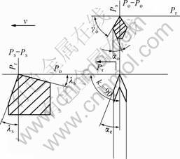
Fig.2 Parameters of special plough tool in principal section system
3 Results and discussion
3.1 Experimental results
Through the experiment, it is found that a bulge appears between the plough tool’s rake face and the tool major cutting edge during the plough, as shown in Fig.4. And the size of bulge grows as the parameters of plough grow. It is also found that with different plough parameters, the red copper can be ploughed into four different kinds of fins, which are gestation fin, multi-dimensional fin, tumor and overlap fin.
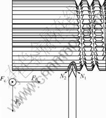
Fig.3 Schematic map of plough

Fig.4 Images of four types of fins during extrusion-plough process: (a) Gestation; (b) Multi-dimensional fin; (c) Tumor; (d) Overlap
3.2 Discussion
3.2.1 Formation mechanism of bulge
It is found, as shown in Fig.5, the bulge near the face grows with the increase of plough depth and plough angle during the plough; the size of bulge near the tool main cutting edge is related to the corner radius, and it diminishes as the corner radius diminishes; the corner radius should be below 0.1 mm to ensure there is no chip. The bulge on the front of tool major cutting edge will also not apparent on this condition. At the same time, the bulge size is also related to the base’s plasticity, the bulge will be bigger when the plasticity is higher. In Fig.5, Fr is tool face tangential force, αp is back engagement of the cutting edge and f is feed. Figs.5(a) and (b) show the red
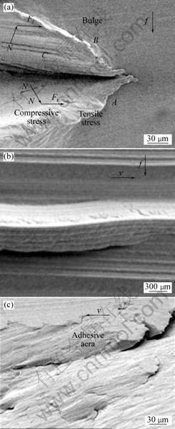
Fig.5 SEM images of bulge during plough: (a) SEM image of plough on copper; (b) SEM image of plough on aluminum alloy; (c) Magnified image of plough interface on aluminum
copper and A-alloy, respectively. The bulge in Fig.5(a) is obvious while that in Fig.5(b) is not. And then abscission comes out in Fig.5(b) along the cutting feed. The main reason for bulge is that the normal pressure resulted from tool’s plough applies on the base, and generates compression stress around the contacting area between the base and tool and tensile stress near the bulge’s brim. Owing to Ff, the metal along the feed is subjected to the extra normal pressure, so the stress in area AC is larger than that in area BC. The differences between the two are related to the feed. While the feed is less than cutting depth, the stress difference increases as the feed increases; otherwise, the difference holds the line. Due to the resistance to the normal pressure, the tensile stress reaches the maximum in the deformation brim A and the compression stress also gets to the maximum in brim C. Because for metals, the compression capacity is generally bigger than tension capacity, metal reaches the tension limit in brim A at first when the bulge grows to a certain size, and the cracks appear. As the cracks extend, the normal pressure slows down; since the sectional area is also reduces, the capacity to resist the deformation is weakened, and here friction Fr plays the critical role to decide the extending of cracks.
The friction between the tool and workpiece is also made up of two parts, which are adhesive force and plough force that resulted from abrasive wearing. Since the plough is a kind of non-chip processing, the back engagement of the cutting edge is great; the nominal contacting area between tool and base is a little more than that in the turning, so the heat in metal cutting is much in the plough. Even though the nonferrous metal has better ability in heat transmission than that of ferrous metal, lacking the radiating of chip, more than 50% cutting heat will accumulate around the contacting area and results in the local hyperthermia, so the tool will adhere to the workpiece around the tool corner contacting area. The metal in the adhesive spot then is torn as the friction goes forward. The extrusion and friction keep on existing between the rake face and the adhesive spot, and because of work-hardening, the metal in the adhesive spot stops adhering, and the primary adhesive spot is rubbed down (Fig.5(c)). Since tool’s rigidity is bigger than that of fin tube, most of the breakage of adhesive spots appear on workpiece’s side during tool’s lifecycle. In Figs.5(a)-(c), plough vestiges on the friction surface can be found obviously. It is because of the rough rake face which has a lot of hard bulges, and its rigidity is far bigger than the workpiece. When the movement between rake face and workpiece happens, the vestiges are generated. The total friction, which will result in extra tension, is placed on the bulge’s contacting area. And the extra tension will promote the aforementioned cracks when it reaches certain value, and finally makes the bulge break away from the base. Because of the friction, the abscised bulge will bend towards tool.
3.2.2 Gestation fin
The gestation fin, as shown in Fig.6, has macro 3D structure, its fin height is 1-4 mm, its depth is 1-2 mm, and fin’s depth≈(0.5-1)×fin’s width; fin’s interval is 2-4 mm, which assures adequate contact between fin and air. Some layer vestige can be seen from the fin’s surface. On the condition that the feed is more than bulge’s influencing field in the plough, the gestation fin will appear. This can be realized by changing the machining parameters. The outer area of workpiece firstly contacts the tool major cutting edge along the feed direction. And owing to the tool’s extrusion and plough, bulge is generated. Since the workpiece has high elastic-plasticity, the elastic deformation weakens the plastic deformation, and when the stress surpasses the elastic limit, the metal will slip and result in the local plastic deformation. The layered accumulation forms one side of the fin. Along the right about of feed, metal has enough space for elastic deformation, so the bulge has smaller size.

Fig.6 SEM image of gestation fin
The changes of plough force are shown in Fig.7. Due to the influence of rolling on plough, the values of Fc, Fp and Ff are fluctuated around a certain value, and the fluctuating amount increases as the rolling depth increases. Different from the traditional cutting, the values of Fc and Fp are almost equal during plough; it is because bulge’s deformation generates great resistance to the tool. Here, Ff≈0.3×Fc, but we can see the direction of Ff and Fc is opposite. It is because during the fabricating, the deformation is not only affected by the horizontal component of N1, but also the horizontal component of N2, whose direction is opposite to N1. When the feed increases to a certain value, N2 will be bigger than N1.

Fig.7 Cutting force image of gestation fin
3.2.3 Multi-dimensional fin
Multi-dimensional fin, shown in Fig.8 is made up of two parts which are macro fin and substructure 3D fin. The macro fin is integrated with base, whose height, width and intervals are near those of gestation fin, and its depth≈(0.1-3)×fin’s width. The substructure appears on the macro fin’s tip, and it looks like a cockscomb. This fin comes out on the conditions that the feed is less than size of bulge’s influencing field, and the volume of fin in single plough is bigger than that of the extruded fin by tool’s rake face. Influenced by the bulge generated in the last plough, the contacting area between tool’s rake face and the base increases and the heat in metal cutting is augmented. Owing to the coactions of heat in metal cutting and compression stress, great plastic deformation is appeared in the fin’s tip, and then the cockscomb-like substructure comes into being. Because of the effect of friction, the deformation grade and velocity increase near the rake face. This point can be verified by Fig.9. Compared with gestation fin, the axial thrust force is enhanced, which becomes one of machine major power consumption.

Fig.8 SEM image of multi-dimensional fin tube

Fig.9 Cutting force image of multi-dimensional fin
Multi-dimensional fin is pretty efficient in heat transmission[7]. For single macrostructure fin, the strengthened heat transmission is realized by the macro flowing of heat-changing current and larger surface area. The superficial current is mainly the laminar flow. Since the heat-transmission coefficient neither in cooling nor in convection is enhanced, the heat-transmission coefficient calculated with the real area under this high finned condition is even less than the ordinary smooth tube[1]. The appearance of substructure fin can be used as the vortex core to induce the vortex in fin’s superficial layer, so that the strengthened heat transmission can be realized by increasing the heat-transmission coefficient[6,12], and the effect is distinct.
3.2.4 Tumor
Tumor is the superposition of two macro fins. And it is the advanced type of substructure in the tip of multi-dimensional fin as shown in Fig.10. Because the macro fin in the tip can jam the bottom intervals and hinder the radiation, moreover, the tip macro fin is liable to be broken and thus result in chips, it isn’t favorable for machining and heat transmission. The tumor comes out on the conditions that the volume of fin in single plough is equal to that of the extruded fin by tool’s rake face. It can be said that tumor is the critical point from multi-dimensional fin to overlap. It is found that enhancing the plough velocity can favor the forming of tumor by experiment.

Fig.10 SEM image of tumor
The SEM image of tumor obviously shows the adhesive vestige. Different from the bulge’s adhering, some adhesive chip and cracks vertical to the cutting direction exist on friction surface; because in this process, both friction force and heat in metal cutting reach to the maximum, the balance of the compression stress and tensile stress of the maximum stress which is accumulated in the bulge from the last plough is broken and released, partial metal of bulge undergoes great plastic deformation and grows along the rake face. As the bulge grows much faster than substructure fin in formation stage and the friction between the bulge and rake face happens instantly, the friction is relative small, so some adhesive chip breaks away from the bulge’s surface and becomes chip. Meanwhile, resulted from the friction, the bulge turns with a certain angle relative to the macrostructure. Fig.11 shows that Fc and Fp are further enhanced; while Ff doesn’t change much, its varied frequency reduces a lot and varied amplitude increases.
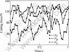
Fig.11 Cutting force image of tumor
3.2.5 Overlap fin
The overlap’s formation is a gradual process as shown in Fig.12. The overlap fin will grow one more knar as the workpiece turns a round, and the crease can obviously observe between each knar. The overlapped fin tube still has gestation or multi-dimensional fin after being ploughed, but its scale is greatly lessened. Fig.12(a) shows the SEM image of fresh overlap fins and formed overlap fins. On the condition that the volume of fin in single plough is bigger than that of the extruded fin by tool’s rake face[11], the overlap fin can be formed. And the increase of difference of those two volumes can accelerate overlap fins’ growth. From Fig.13, it can be seen that Ff becomes the maximum, and comparing with the former 3 stages, its varied amplitude increases a little
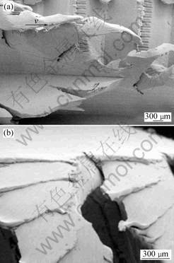
Fig.12 SEM images of overlap fin: (a) Forming image of overlap; (b) Growing image of overlap
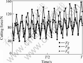
Fig.13 Cutting force image of overlap fin
further. All of Ff, Fc and Fp increase as time goes by, while Ff increases the most quickly, and these can be taken as the criterion for the appearance for this fin. The overlap fins will grow bigger as time goes by because of the accumulation. Fig.12(b) shows the elder overlap. The accumulated metal vestiges can obviously be seen, and the volume of every knar just equals the difference of the two volumes mentioned above.
4 Conclusions
1) With different machining parameters, four different kinds of fins can be generated in the plough process, which are gestation fin, multi-dimensional fin, tumor and overlap fin. Multi-dimensional fin has high heat transmission efficiency, and it is a kind of complicated fin with cockscomb-like 3D substructure fin on the tip of 3D macrostructure fin.
2) The bulge’s size increases with the increase of plough depth, plough angle and work’s plasticity. Work’s plasticity decides combination of bulge and base; when the plasticity is small, the bulge will break away from the base under the primarily complicated stress resulted from plough tool and the secondarily friction.
3) The condition for gestation fin is that the feed is more than bulge’s influencing field in the plough. The condition for multi-dimensional fin is that the feed is less than size of bulge’s influencing field, and the volume of fin in single ploughing is bigger than that of the extruded fin by tool’s rake face. The condition for tumor is that the volume of fin in single plough is equal to that of the extruded fin by tool’s rake face. The condition for overlap is that the volume of fin in single plough is bigger than that of the extruded fin by tool’s rake face.
References
[1] ZHAO Xiao-xi, DENG Xian-he. Heat transfer enhancement performance of lozenge fin tube[J]. Science & Technology in Chemical Industry, 2002, 10: 1-3.(in Chinese)
[2] SINGH S K, KUMAR R. Heat transfer during condensation of steam over a vertical grid of horizontal integral-fin copper tubes[J]. Applied Thermal Engineering, 2001, 21: 717-730.
[3] HE Y L, TAO W O. Three-dimensional numerical study of heat transfer characteristics of plain plate fin-and-tube heat exchangers from view point of field synergy principle[J]. International Journal of Heat and Fluid Flow, 2005, 26: 459-473.
[4] RASOULI S, GOLRIZ M R, HAMIDI A A. Effect of annular fins on heat transfer of a horizontal immersed tube in bubbling fluidized beds[J]. Powder Technology, 2005, 154: 9-13.
[5] LEU J S, WU Y H, JAN J Y. Heat transfer and fluid flow analysis in plate-fin and tube heat exchangers with a pair of block shape vortex generators[J]. International Journal of Heat and Mass Transfer, 2004, 47: 4327-4338.
[6] SOMMERS A D, JACOBI A M. Air-side heat transfer enhancement of a refrigerator evaporator using vortex generation[J]. International Journal of Refrigeration, 2005, 28: 1006-1017.
[7] FIEBIG M. Vortices generators and heat transfer[J]. Trans Inst Chem Eng, 1998, 76(A): 108-123.
[8] CHAMRA L M, WEBB R L. Advanced micro-fin tubes for evaporation[J]. Int J Heat Mass Transfer, 1996, 39: 1827-1838.
[9] LIU Wei, TANG Yong. Processing of cylindrical three-dimension fins and formation of burrs[J]. Journal of South China University of Technology, 2004, 32: 9-13. (in Chinese)
[10] TANG Yong. Study on the mechanism of extrusion-ploughing during manufacturing copper outside fin tube[J]. Tool Engineering, 1997, 31: 7-10. (in Chinese)
[11] TANG Yong, LIU Shu-dao. The establishment and analysis of fin formation model during ploughing process[J]. Journal of Materials Processing Technology, 2003, 138: 390-393.
[12] LI Long-jian, CUI Wen-zhi. Heat transfer augmentation in 3D internally finned and micro finned helical tube[J]. International Journal of Heat Transfer, 2005, 48: 1916-1925.
(Edited by YANG You-ping)
Foundation item: Projects (50436010, 50375055) supported by the National Natural Science Foundation of China; Project (04105942) supported by the Natural Science Foundation of Guangdong Province, China
Correspondence: TANG Yong; Tel: +86-20-87114634; E-mail: ytang@scut.edu.cn

