Trans. Nonferrous Met. Soc. China 29(2019) 701-709
Effect of precipitate evolution on corrosion behavior of friction stir welde joints of AA2060-T8 alloy
Qiang MENG1, Yang LIU2, Ju KANG3, Rui-dong FU2, Xiao-yan GUO2, Yi-jun LI2
1. AVIC Manufacturing Technology Institute, Beijing 100024, China;
2. State Key Laboratory of Metastable Materials Science and Technology, College of Materials Science and Engineering, Yanshan University, Qinhuangdao 066004, China;
3. Beijing Higher Institution Engineering Research Center of Energy Engineering Advanced Joining Technology, Beijing Institute of Petrochemical Technology, Beijing 102617, China
Received 29 April 2018; accepted 16 November 2018
Abstract: Friction stir welding was used to join two AA2060-T8 plates, and then the effect of precipitate evolution on microstructure and corrosion behavior of the joint was investigated. The evolution of precipitates on the top surface of the joint was characterized by scanning electron microscopy and transmission electron microscopy. The corrosion behaviors of different regions in the joint were investigated by an electrochemistry method and an alternating salt spray exposure. The corrosion was mainly dependent on the nature of precipitates in each region of the joint. The shoulder affected zone had the worst corrosion resistance as a result of the re-dissolved of �ȡ�(Al2Cu), T1(Al2CuLi) and �ġ�(Al3Li) phases, the formation of intergranular precipitates and precipitate-free zones. However, the thermomechanically affected zone had a slightly improved corrosion resistance because it had no intergranular precipitates. The heat affected zone and base metal had the best corrosion resistance.
Key words: 2060-T8 aluminum alloy; friction stir welding; precipitate; microstructure; micro-electrochemical characteristics
1 Introduction
Aluminum alloy 2060-T8 (AA2060-T8) is one of the third generation of aluminum-lithium (Al-Li) alloy, which has a great potential of applications in the aircraft primary structures owing to its low density, high specific strength and toughness [1,2]. However, it is difficult to join by the traditional fusion welding methods because of serious metallurgical defects, such as cavity and solidification cracking [3,4]. As an innovative solid-state joining technology, friction stir welding (FSW) provides a satisfactory alternative method to weld aluminum alloys [5,6].
As a precipitation hardened aluminum alloy, Al-Li alloy contains a wide variety of precipitates, depending upon heat treatment conditions, mainly including Guinier-Preston (GP) zones, T1(Al2CuLi), �ġ�(Al3Li), �ȡ�(Al2Cu), �¡�(Al3Zr), and S��(Al2CuMg) [3,7]. Since different regions of the FSW joint undergo different thermal cycles during welding, the FSW joint can be divided into four regions, namely weld nugget zone (WNZ), thermomechanically affected zone (TMAZ), heat affected zone (HAZ) and base material (BM) [8,9]. As is well known, the nature of precipitates in each region plays a key role for the performance of the FSW joints of precipitation hardened aluminum alloys [10]. KANG et al [11,12] found that the tensile strength of the FSW joint of AA2219-T8 could reach about 80% that of the BM. The weakened strength was attributed to the coarsened �ȡ� phase in the HAZ. MAHONEY et al [13] found a similar result in the FSW joint of AA7075.
Except for the mechanical properties, the corrosion behavior also strongly relies on the nature of precipitates for the FSW joint of high strength aluminum alloy [8]. The most common corrosion type occurred in the FSW joints of high strength aluminum alloys is the local corrosion including pitting corrosion, intergranular corrosion and stress corrosion cracking (SCC) [14-17]. BOUSQUET et al [18] revealed that the pitting corrosion possessed the dominated feature in the TMAZ of the AA2024 FSW joint, and it was proved to be related to the S�� (Al2CuMg) phase. WADESON et al [19] found that the intergranular corrosion extended through the TMAZ to HAZ in the FSW joint of AA7108-T79. The intergranular corrosion was triggered because of the non-uniform distribution of �� (MgZn2) phases along the grain boundaries. PAGLIA and BUCHHEIT [20] reported that the SCC susceptibility of the AA2219-T8 FSW joint was generally low as a result of the resolutionizing and coarsening of the intragranular precipitates during welding. Nevertheless, the previous researches on the corrosion performance of the FSW joint of high strength aluminum alloys are mostly based on the standard corrosion test methods, which cannot reflect the corrosion evolution for longer periods under an actual environment, such as the marine environment characterized by high concentration of chloride ions and humidity levels with alternating dry and humid condition.
Therefore, the corrosion behavior of the top surface of an AA2060-T8 FSW joint was investigated in this work. An electrochemistry method was used to study the micro-electrochemical characteristics of the joints. The corrosion morphologies were observed after the joint underwent an alternating salt spray exposure. A better understanding of the correlation was provided between the precipitate evolution and corrosion of the AA2060-T8 FSW joints.
2 Experimental
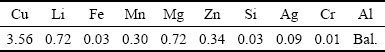
The base material used in the present study was 2 mm-thick AA2060-T8 rolled plates. The chemical composition of this alloy is listed in Table 1. The plates were butt-welded using the FSW process at a rotation speed of 600 r/min and a welding speed of 400 mm/min in the clockwise direction. The welding direction was perpendicular to the rolling direction.
Table 1 Chemical composition of 2060 aluminum alloy (wt.%)
Electrical discharge machining was used to cut the top-surface samples and the transverse samples from the joint. The metallographic specimens were ground and then polished with 1 ��m diamond paste, etched with Keller reagent, and observed by optical microscopy (OM, AXIOVERT 200 MAT). Scanning electron microscopy (SEM, HITACHI S-4800) with energy dispersive spectroscopy (EDS, HORIBA EDAX) was used to obtain the morphology, size, and chemical compositions of the constituent particles in different regions of the joint. Transmission electron microscopy (TEM, JEOL-2010) was used to study the type and size of the precipitates in different regions. Differential scanning calorimetry (DSC, NETSCH STA449C) was performed to characterize the type and content of the precipitates in each region of the joint.
All of the samples for electrochemistry and salt spray test were mechanically ground to 1200 grit finish with ethanol to minimize corrosion during sample preparation, cleaned ultrasonically in ethanol, and finally dried by cold air. Electrochemical workstation (CHI600d) was used to study the micro-electrochemical characteristics of different regions on the top surface. Figure 1 shows a schematic of the three-electrode system used to perform the testing. A Pt counter electrode and saturated calomel reference electrode (SCE, 242 mV (SHE)) were used. The samples were held at the open circuit potential (OCP) for 10 min to ensure that the working electrode reached a steady state, and then polarized from -2.0 to 0 V with respect to the OCP at a scan rate of 10 mV/s. An aerated 3.5 wt.% NaCl solution at room temperature (25��2) ��C was used. Each test was repeated at least five times, and the average values and standard deviations were reported. Alternating salt-spray test of the joints was carried out according to the IEC 60068-2-52:1996 standard with the periods of 4, 8, 12 and 16 d, respectively. Topographic analysis of the corroded top surface was performed using OM and SEM.
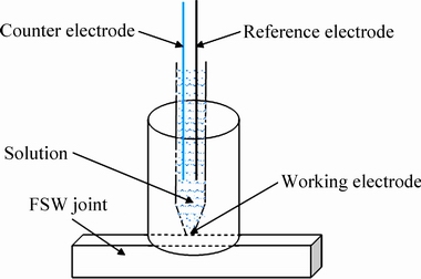
Fig. 1 Schematic of three-electrode system
3 Results and discussion
3.1 Microstructural characterization
A macroscopic metallographic image of the cross section of the AA2060 FSW joint is shown in Fig. 2. The cross section can be divided into five distinct regions: shoulder affected zone (SAZ), WNZ, TMAZ, HAZ, and BM. Approximately 0.3 mm of the top surface was removed by grinding to eliminate the surface texture induced by welding. The depth of removal was approximately the plane represented by the green dashed line in Fig. 2. The surface was then polished and etched to reveal the surface microstructures, as shown in Fig. 3(a). The joint surface can be divided into four regions: SAZ, TMAZ, HAZ, and BM. The WNZ is buried beneath the SAZ, so it is not visible on this top surface.
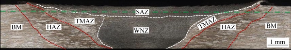
Fig. 2 Macroscopic metallographic image showing cross section of AA2060 FSW joint
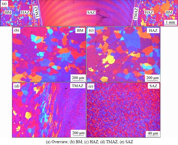
Fig. 3 Microstructures on top surface of FSW joint
The typical microstructures in term of BM, HAZ, TMAZ and SAZ are presented in Fig. 3. It can be found that the most difference among various regions was related to the grain shape and size. The microstructure feature of the BM and HAZ was almost identical (see Figs. 3(b) and (c)). The TMAZ exhibited mixture microstructures of refined and elongated grains (see Fig. 3(d)) due to the action of the welding thermal cycles and the friction on the edge of welding tool shoulder. Figure 3(e) displays the morphology of the SAZ, showing fine equiaxed grains as the result of dynamic recrystallization. Further observation in Fig. 3(a) shows that many regular arc-shaped bands were presented in the SAZ region. These bands are coincident with the ��onion rings�� feature in the cross section of the WNZ produced by the periodical extrusion action of the tool pin. SUTTON et al [21] also found the similar microstructure features due to the metal plastic flow driven by the shoulder of the tool in the surface layer of the FSW joint.
3.2 Evolution of precipitates
Backscattered electron (BSE) micrographs of the constituent particles in different regions are presented in Fig. 4. In the BM, there was an abundance of coarse particles (labeled as arrow in Fig. 4(a)). EDS analysis was performed on the particles in Fig. 4(a). Particle 1 was found to be 60.8 at.% Al, 9.86 at.% Cu, and 1.96 at.% Fe, indicating that it was Fe-containing phase, which is generally considered as an impurity phase mainly coming from the original casting structure. The Al-Cu-Fe phase plays a similar role to the Al2Cu phase in corroding the adjacent Al matrix due to its similar corrosion potential. Similar distribution feature of the Fe-containing phase can be found in the HAZ (Fig. 4(b)). The particles were smaller in the SAZ than that in the BM mainly relating to the broken Fe-containing particles by the welding tool pin and the partial dissolution of the Al2Cu phase particles because of the high welding temperature [8], as shown in Fig. 4(c).
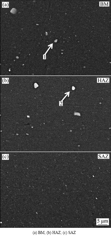
Fig. 4 BSE micrographs of constituent particles in different regions
The bright-field TEM micrographs and associated selected area diffraction (SAD) patterns in Fig. 5 show the evolution of precipitates in the AA2060-T8 FSW joint. Figures 5(a) and (b) show the types and distribution of the precipitates in the BM. The rod-shaped particles with a length of about 400 nm and a diameter of about 200 nm were frequently observed (see Fig. 5(a)). The corresponding SAD pattern in Fig. 5(a) shows that the precipitates were �ȡ� phases. The acerose precipitates with a length of 60-100 nm were found under a higher magnification observation (see Fig. 5(b)). These precipitates were proved to be T1 phase, another strengthening phase in the Al-Li alloy, by selected electron diffraction (see the insert image in Fig. 5(b)). After the FSW process, the �ȡ� phase coarsened in the TMAZ (see Fig 5(c)) and T1 phase got partially re-dissolving (see Fig. 5(d)). Moreover, some of smaller spherical precipitates were also observed in the matrix (the arrow shown in Fig. 5(c)). The corresponding SAD pattern in Fig. 5(c) shows that the fine precipitates were identified as �ġ� phase. The precipitate morphologies were obviously refined in the SAZ, which were significantly different from those in the BM (see Figs. 5(e) and (f)). Firstly, it is attributed to the high peak temperature, which results in the dissolving of the precipitates, and then the fast cooling rate restricts the re-precipitation process of these precipitates. In addition, the mechanical fragmenting action by the welding tool pin may also attribute to the refinement of the precipitates in the SAZ. A notable result is the formation of intergranular precipitates and precipitation-free zones (PFZ) in the SAZ (see Fig. 5(f)) [22]. The intergranular precipitates and PFZ both will result in intergranular corrosion in the SAZ [8,18,20].
Figure 6 shows DSC curves of different regions in an AA2060-T8 FSW joint. Based on the previous literatures [11,23], the first endothermic peak (Peak I, about 170 ��C) corresponded to the redissolution of the GP(I) zones and the second endothermic peak (Peak II, about 220 ��C) corresponded to the redissolution of the GP(II) zones and �ġ� phase. The exothermic peak (Peak III, about 250 to 310 ��C) corresponded to the formation of the T1 phase.
It is well known that the areas under the endothermic peak reflect the volume fraction of the dissolved precipitates, which are equal to that existed in the as-welded joints. In contrast, the exothermic peak areas reflect the volume fraction of the re-precipitated phases during the DSC heating stage. The larger the area under the exothermic peak is, and the little the metastable phase in the as-welded joints is. Obviously, the DSC curve of the SAZ exhibited the largest endothermic peak area, which indicates that the volume fraction of GP zones and �ġ� phases in this region was the highest for the as-welded joint. The exothermic peak area of the SAZ was also larger than that in other regions of the joint. This suggests that the volume fraction of the T1phases in the SAZ of the as-welded joint was lower. The DSC results well correspond to the TEM observations.
3.3 Corrosion behavior under alternating salt-spray environment
The alternating salt-spray test is an alternative approach to investigate the corrosion behavior under simulated marine environment. The topography of corrosion morphology formed on the top surface of the joint after being exposed for different periods during alternating salt-spray test is displayed in Fig. 7. In the initial stage, the slight pitting corrosion occurred in the SAZ and TMAZ (Fig. 7(b)). It shows that the resistance to local corrosion was relatively poor for these two regions. After exposure for 8 d (Fig. 7(c)), the corrosion products have covered the surface. When being exposed for 12 d (Fig. 7(d)), some of the corrosion products started to peel off. It can be deduced that the pittings have expanded and connected together in this stage. The corrosion evolution in final stage further confirms that the most severe attack preferred appearing near the TMAZ (see Fig. 7(e)).
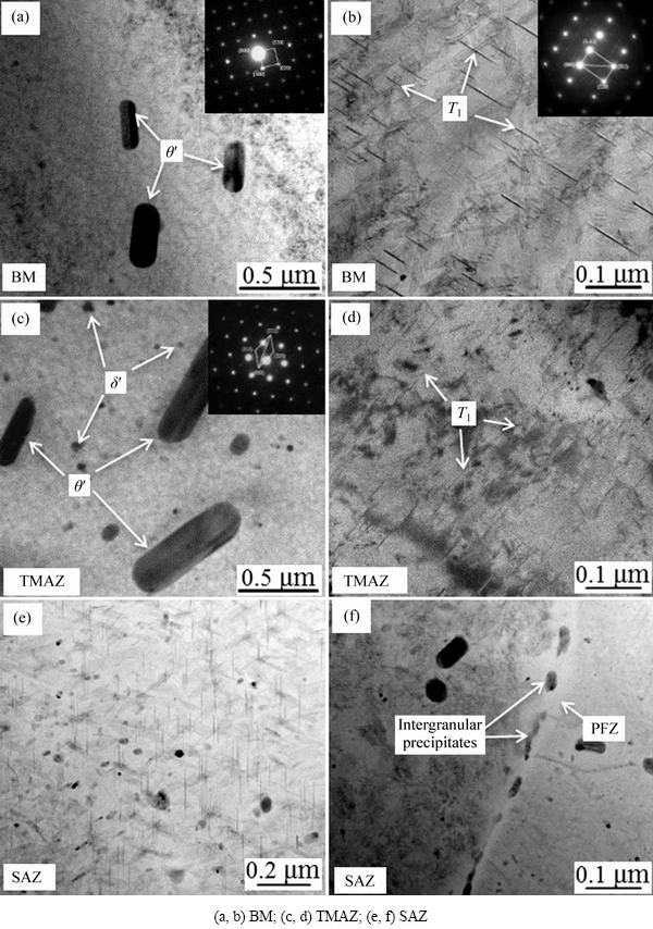
Fig. 5 TEM micrographs and associated SAD patterns through AA2060-T8 FSW joint
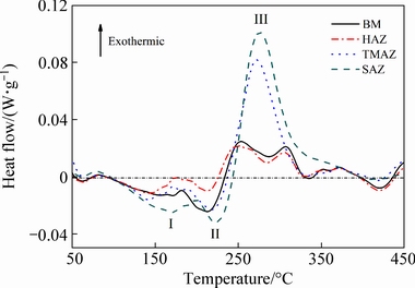
Fig. 6 DSC curves of different regions in AA2060-T8 FSW joint
Further SEM observations on corrosion features of different regions in the joint are shown in Fig. 8. Overall, the corrosion evolution in each region of the joint exhibited a similar feature. With increasing exposure periods, the corrosion became severer and the corrosion products became thicker. In the final stage of the exposure, the corrosion products have covered the entire surface of the joint. It is noteworthy that the preferential attacks occurred at the peak positions on the surface of arc stringer regions of the SAZ (see the image at the 4th day). Subsequently, the valley positions of these regions corroded after being exposed for 8 d. The above features were related to the distribution of the second phase particles in these arc stringer regions [24]. KANG et al [24,25] reported that the density of the second phase particles at the peak position was higher than that at the valley position. Furthermore, compared to the BM, the corrosion products were more loose and porous in the TMAZ. The corrosion behavior of the HAZ was similar to that of the BM due to the similar microstructures.
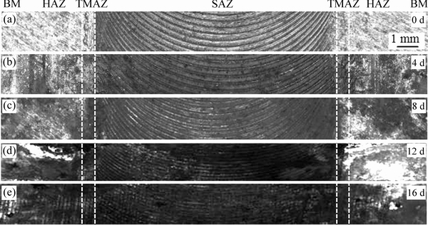
Fig. 7 Corrosion morphologies of FSW AA2060 joints exposed for different test periods
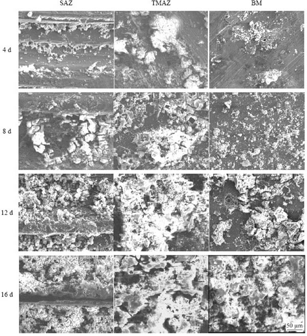
Fig. 8 Corrosion evolution in different regions of joint exposed for different test periods
Several factors can affect the corrosion behavior of aluminum alloys, such as the precipitates and constituent particles, grain boundary structure and composition, grain solid solution composition, grain size and crystal defects [8,18,19,25-28]. After FSW, the size of grains in the SAZ is fine, and the dislocation density increases, which both promote the surface activity of the SAZ resulting in the decline of the corrosion resistance [26-28]. It should be pointed out that among these factors, the precipitates and constituent particles have the most significant effect on pitting corrosion of the precipitation hardened aluminum alloy. For the AA2060-T8 FSW joint, the �ȡ� phase coarsened, whereas the T1 partially re-dissolved in the TMAZ, which resulted in the decreased corrosion resistance of the TMAZ. In the SAZ, as a result of the combined action of the welding thermal cycles and the stir of the welding tool pin, the peak temperature was the highest. Therefore, the precipitates were partly re-dissolved, which led to the increased content of active element of Li in the matrix, leading to a promotion of the local corrosion.
3.4 Polarization curves in 3.5 wt.% NaCl solution
Polarization curves were measured for different regions of the top surface of the joint in aerated 3.5 wt.% NaCl solution with the three-electrode system. Figure 9(a) displays typical polarization curves of the different regions. The values of corrosion potential (��corr) which were measured in various regions of the joint at least five times, are shown in Fig. 9(b). The results reveal that the ��corr in the SAZ was the lowest at -0.991 V (vs SCE), followed by the ��corr in the TMAZ at -0.917 V (vs SCE), the ��corr in the BM was significantly higher, at -0.717 V (vs SCE). In other words, the resistance to local corrosion of the SAZ and TMAZ was relatively poor.
As shown above, for the AA2060-T8 FSW joint, the microstructures in the SAZ included �ȡ� phase refining, T1 phase re-dissolving, the formation of intergranular precipitates and the deleterious PFZ. The re-dissolved T1 phase into the matrix phase resulted in a high content of the active element of Li in the alloy matrix, which decreased the ��corr of the SAZ. Moreover, the formation of precipitates at the grain boundaries and the existence of the PFZ triggered IGC. The combined effects of the above factors made SAZ the most severely corroded region. The second phase particles in the TMAZ were similar to those in the SAZ, but no intergranular precipitates and PFZ, which improved the local corrosion resistance.
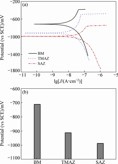
Fig. 9 Polarization curves of different regions on FSW joint top surface (a) and ��corr of different regions (b)
4 Conclusions
(1) The microstructure in different weld regions changed as a result of the thermomechanical processing. The �ȡ� phase, T1 phase and a little coarse Fe-containing phase were observed in the BM and HAZ. In the TMAZ, the �ȡ� phase coarsened, whereas the T1 phase partially re-dissolved. The microstructures in the SAZ included �ȡ� phase refining, T1 phase re-dissolving, the formation of intergranular precipitates and the deleterious PFZ.
(2) The resistance to corrosion, as estimated by the salt spray corrosion behavior and ��corr, was the worst in the SAZ, which slightly improved in the TMAZ, and was the best in the HAZ and BM.
(3) The preferential attacks occurred at the peak position of arc shaped stringers on the surface of the SAZ, where the density of the second phase particles was higher.
Acknowledgments
The authors wish to express sincere thanks to Beijing Natural Science Foundation (Grant No. 3194048), to China Friction Stir Welding Center and to Beijing Key Laboratory of Pipeline Critical Technology and Equipment for Deepwater Oil & Gas Development (Grant No. BIPT2018006) for the financial support.
References
[1] ZHANG X Y, YANG W X, XIAO R S. Microstructure and mechanical properties of laser beam welded Al-Li alloy 2060 with Al-Mg filler wire [J]. Materials & Design, 2015, 88: 446-450.
[2] DE P S, MISHRA R S, BAUMANN J A. Characterization of high cycle fatigue behavior of a new generation aluminum lithium alloy [J]. Acta Materialia, 2011, 59(15): 5946-5960.
[3] LIU H J, HU Y Y, DOU C, SEKULIC D P. An effect of the rotation speed on microstructure and mechanical properties of the friction stir welded 2060-T8 Al-Li alloy [J]. Materials Characterization, 2017, 123(1): 9-19.
[4] LI Q, WU A P, LI Y J, WANG G Q, QI B J, YAN D Y, XIONG L Y. Segregation in fusion weld of 2219 aluminum alloy and its influence on mechanical properties of weld [J]. Transactions of Nonferrous Metals Society of China, 2017, 27(2): 258-271.
[5] ZHANG Q Z, GONG W B, LIU W. Microstructure and mechanical properties of dissimilar Al�CCu joints by friction stir welding [J]. Transactions of Nonferrous Metals Society of China, 2015, 25(6): 1779-1786.
[6] SHARMA N, KHAN Z A, SIDDIQUEE A N. Friction stir welding of aluminum to copper��An overview [J]. Transactions of Nonferrous Metals Society of China, 2017, 27(10): 2113-2136.
[7] YOSHIMURA R, KONNO T J, ABE E, HIRAGA K. Transmission electron microscopy study of the evolution of precipitates in aged Al-Li-Cu alloys: The �ȡ� and T1 phases [J]. Acta Materialia, 2003, 51: 4251-4266.
[8] KANG J, FENG Z C, FRANKEL G S, LI J C, ZUO G S, WU A P. Effect of precipitate evolution on the pitting corrosion of friction stir welded joints of an Al-Cu alloy [J]. Corrosion, 2016, 72(6): 719-731.
[9] XU W F, LIU J H. Microstructure evolution along thickness in double-side friction stir welded 7085 Al alloy [J]. Transactions of Nonferrous Metals Society of China, 2015, 25(10): 3212-3222.
[10] CHEN Y C, LIU H J, FENG J C. Friction stir welding of 2219-T6 aluminum alloy [J]. Transactions of Nonferrous Metals Society of China, 2005, 15(2): 75-78.
[11] KANG J, FENG Z C, FRANKEL G S, HUANG I W, WANG G Q, WU A P. Friction stir welding of Al alloy 2219-T8: Part I��Evolution of precipitates and formation of abnormal Al2Cu agglomerates [J]. Metallurgical and Materials Transactions A, 2016, 47(9): 4553-4565.
[12] KANG J, FENG Z C, LI J C, FRANKEL G S, WANG G Q, WU A P. Friction stir welding of Al alloy 2219-T8: part II��Mechanical and corrosion properties [J]. Metallurgical and Materials Transactions A, 2016, 47(9): 4566-4577.
[13] MAHONEY M W, RHODES C G, FLINTOFF J G, BINGEL W H, SPURLING R A. Properties of friction-stir-welded 7075 T651 aluminum [J]. Metallurgical and Materials Transactions A, 1998, 29(7): 1955-1964.
[14] DHANAPAL A, BOOPATHY S R, BALASUBRAMANIAN V. Corrosion behaviour of friction stir welded AZ61A magnesium alloy welds immersed in NaCl solutions [J]. Transactions of Nonferrous Metals Society of China, 2012, 22(4): 793-802.
[15] JAYARAJ R K, MALARVIZHI S, BALASUBRAMANIAN V. Electrochemical corrosion behaviour of stir zone of friction stir welded dissimilar joints of AA6061 aluminium-AZ31B magnesium alloys [J]. Transactions of Nonferrous Metals Society of China, 2017, 27(10): 2181-2192.
[16] SU J Q, NELSON T W, STERLING C J. Microstructure evolution during FSW/FSP of high strength aluminum alloys [J]. Materials Science and Engineering A, 2005, 405(1-2): 277-286.
[17] RHODES C G, MAHONEY M W, BINGEL W H, SPURLING R A, BAMPTON C C. Effects of FSW on microstructure of 7075 aluminum [J]. Scripta Materialia, 1996, 36(1): 69-75.
[18] BOUSQUET E, POULON Q A, PUIGGALI M, DEVOS O, TOUZET M. Relationship between microstructure, microhardness and corrosion sensitivity of an AA 2024-T3 friction stir welded joint [J]. Corrosion Science, 2011, 53(9): 3026-3034.
[19] WADESON D A, ZHOU X, THOMPSON G E, SKELDON P, OOSTERKAMP L D, SANMANS G. Corrosion behaviour of friction stir welded AA7108 T79 aluminium alloy [J]. Corrosion Science, 2006, 48(4): 887-897.
[20] PAGLIA C S, BUCHHEIT R G. Microstructure, microchemistry and environmental cracking susceptibility of friction stir welded 2219-T87 [J]. Materials Science and Engineering A, 2006, 429: 107-114.
[21] SUTTON M A, YANG B C, REYNOLDS A P, TAYLOR R. Banded microstructure in 2024-T351 and 2524-T351 aluminum friction stir welds: Part II. Mechanical characterization [J]. Materials Science and Engineering A, 2004, 364(1-2): 66-74.
[22] JHA S C, JR T H S, DAYANANDA M A. Grain boundary precipitate free zones in Al-Li alloys [J]. Acta Metallurgica, 1987, 35(2): 473-482.
[23] GAO N, STARINK M J, DAVIN L, CEREZO A, WANG S C, GREGSON P J. Microstructure and precipitation in Al-Li-Cu-Mg- (Mn, Zr) alloys [J]. Materials Science and Technology, 2005, 21(9): 1010-1018.
[24] KANG J, LUAN G H, FU R D. Microstructures and mechanical properties of banded textures of friction stir welded 7075-T6 aluminum alloy [J]. Acta Metallurgica Sinica, 2011, 47(2): 224-230.
[25] KANG J, FU R D, LUAN G H, DONG C L, HE M. In-situ investigation on the pitting corrosion behavior of friction stir welded joint of AA2024-T3 aluminium alloy [J]. Corrosion Science, 2010, 52(2): 620-626.
[26] FRANKEL G S. Pitting corrosion of metals: A review of the critical factors [J]. Journal of the Electrochemical Society, 1998, 145(6): 2186-2198.
[27] PANG J J, LIU F C, LIU J, TAN M J, BLACKWOOD D J. Friction stir processing of aluminium alloy AA7075: Microstructure, surface chemistry and corrosion resistance [J]. Corrosion Science, 2016, 106(5): 217-228.
[28] WANG D, NI D R, MA Z Y. Effect of pre-strain and two-step aging on microstructure and stress corrosion cracking of 7050 alloy [J]. Materials Science and Engineering A, 2008, 494(1-2): 360-366.
�������ݱ��2060-T8���Ͻ����Ħ������ͷ��ʴ��Ϊ��Ӱ��
�� ǿ1���� ��2���� ��3������2��������2�����վ�2
1. �й��������켼���о�Ժ������ 100024��
2. ��ɽ��ѧ ���Ͽ�ѧ�빤��ѧԺ ���Ȳ����Ʊ��������ѧ�����ص�ʵ���ң��ػʵ� 066004��
3. ����ʯ�ͻ���ѧԺ ��Դ�����Ƚ����Ӽ��������иߵ�ѧУ�����о�����, ���� 102617
ժ Ҫ�����ý���Ħ������2060-T8���Ͻ��Ľ��к��ӣ��о��������ݱ�Խ�ͷ����֯��ʴ��Ϊ��Ӱ�졣�ڲ���ɨ��羵����羵����2060-T8���Ͻ����Ħ������ͷ�ϱ����������ݱ���Ϊ�Ļ����ϣ�ͨ���绯ѧ����ͽ���������ʴ�����о���ͷ������ĸ�ʴ��Ϊ���о���������ʴ��Ϊ����������������������أ����ڦȡ�(Al2Cu)�ࡢT1(Al2CuLi)��ͦġ�(Al3Li)��Ļ��ܣ��Լ�������������������ij��֣����Ӱ�����Ǹ�ʴ�����е�������Ϊ�����ھ��������࣬������Ӱ�������Ȼ�еӰ�����Ŀ���ʴ����������ߣ���Ӱ������ĸ�ĵĿ���ʴ������á�
�ؼ��ʣ�2060-T8���Ͻ𣻽���Ħ�����������ࣻ����֯�����绯ѧ����
(Edited by Xiang-qun LI)
Corresponding author: Ju KANG, Tel: +86-10-81293719, E-mail: kangju@bipt.edu.cn; Rui-dong FU, Tel: +86-335-8074792, E-mail: rdfu@ysu.edu.cn
DOI: 10.1016/S1003-6326(19)64980-0

