J. Cent. South Univ. Technol. (2007)06-0783-05
DOI: 10.1007/s11771-007-0149-2

2D finite element analysis of thermal balance for drained aluminum reduction cells
LIU Wei(�� ΰ), LI Jie(�� ��), LAI Yan-qing(������), LIU Ye-xiang(��ҵ��)
(School of Metallurgical Science and Engineering, Central South University, Changsha 410083, China)
Abstract: Based on the principle of energy conservation��the applicable technique for drained cell retrofitted from conventional one was analyzed with 2D finite element model. The model employed a 1D heat transfer scheme to compute iteratively the freeze profile until the thickness variable reached the terminating requirement. The calculated 2D heat dissipation from the cell surfaces was converted into the overall 3D heat loss. The potential drop of the system, freeze profile and heat balance were analyzed to evaluate their variation with technical parameters when designing the 150 kA conventional cell based drained cell. The simulation results show that the retrofitted drained cell is able to keep thermal balance under the conditions that the current is 190 kA, the anodic current density is 0.96 A/cm2, the anode-cathode distance is 2.5 cm, the alumina cover is 16 cm thick with a thermal conductivity of 0.20 W/(m����) and the electrolysis temperature is 946 ��.
Key words: drained cell; thermo-electric field; thermal balance; finite element analysis
1 Introduction
The Hall-Heroult technology for aluminum production is the only available method used by the industries for over one century. Technological achievements have occurred in the coming of the large scale cell and the improvement of the automatic control system for decreasing energy cost, and increasing current efficiency (CE), stability and growth in production of primary aluminum. However, to avoid turbulent movement of aluminum and increase CE the conventional cell cannot get rid of its own drawbacks, i.e. poor wettability between the molten aluminum and the cathode block, over 15 cm deep aluminum pad and over 4 cm high anode-cathode distance (ACD), which are main reasons for high energy costs.
Experts have tried to retrofit the conventional cells and put forward new cell structures composed of carbon or inert anodes and wettable cathodes. In order to facilitate the tapping and gas release, the cathode is cut into drained or slopped shapes, at top of which there are arranged sumps, and the anode has a corresponding angle parallel to the cathode[1-4]. Generally, the cell with those characteristics is called drained aluminum reduction cell. Nowadays, inert anodes are still unavailable to meet requirements for large-scale industrial tests and commercial production. But the cell with carbon anodes and coated TiB2 carbon cathodes is possibly close to the final industrialized application. As to this kind of cell, the physical fields have been studied with mathematical models[5-10]. However, for the low ACD can drop its system voltage and change the thermal input and output of the cell, so it is necessary to study the heat balance issue based on designing the lining structure and selecting appropriate operational technologies.
As the heat balance is concerned, the 2D side slice model is easy to be used but unable to compute the global heat dissipation of the whole cell[11]. So the 3D model of the quarter cell is preferred, but the modeling work is huge and heat transfer coefficients are hardly applied. The 3D model can be interpreted as the combination of 2D side slice model and 2D end slice model[12]. In 2D and 3D models, the temperature of the fluids is supposed to be constant and the calculation of profile of side ledge is based on checking the eutectic temperature. In this paper, feasible techniques for drained cells retrofitted from 150 kA conventional ones were analyzed with a 2D finite element (FE) model.
2 Equilibrium equations
2.1 Electric equilibrium
The system voltage  is defined as follows:
 (1)
(1)
where ?Vac is the sum of the back counter electromotive force; ?Vb is the ohmic voltage of bath; ?Va and ?Vc are the voltage drops through the anode and Cathode, respectively; and ?VAE is the additional averaged voltage caused by anode effects (AE). For stable drained cells AE coefficient must be kept as low as possible and therefore ?VAE can be neglected.
2.2 Heat equilibrium
The total input energy Qin is defined as follows:
 (2)
(2)
where Qequ is the energy to hold the electrochemical reactions; Qalu, Qbub, Qair and Qand are energies taken away by tapped aluminum, released anodic bubble, exhaled hot air from the hood and consumed anode respectively; Qlos is the heat loss dissipating out from the bottom, the side (including collector bars), the alumina cover, anodes and rods to the room[13].
2.3 Heat transfer scheme
The 1D heat transfer scheme is described as follows[14]. The heat transfers in 1D model from hot molten liquids to the surface of the ledge via the interface layer with d-thick, then temperature falls from tb to tf. After the heat passes the cool ledge with xf-thick again, temperature becomes ts. According to energy conservation, xf can be given as:
 (3)
(3)
where xf is the thickness of ledge, m; ��f is the thermal conductivity of ledge, W/(m����); hb is the convection coefficient between the liquids and the ledge, W/(m2����); tb, tf and ts are the temperatures of the liquids, surface of ledge and the inside surface of the side carbon blocks, ��.
2.4 Calculation flowchart
The total energy input was calculated with the experiential equations of electric drops and with temperature-dependant resistivities. The 2D heat transfer equation was dispersed by the FEM in the solution domain to build the FE model, on which the temperature and heat exchange boundaries were applied[15]. At the first run of the thermal field, the temperature distribution, the heat loss and the profile of the ledge were obtained. Then the profile was iteratively calculated based on 1D heat transfer scheme until the thickness reached the predicted precision. Finally 3D heat loss of the whole cell was got by expanding 2D to 3D, and then compared with that calculated by Eqn.(2) to ensure that relative errors are small enough. The calculation flowchart is shown in Fig.1 and the FE model of drained cell is shown in Fig.2.
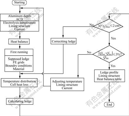
Fig.1 Flowchart of electro-thermal analysis for drained cells
( and
and are calculated ledge thickness in this and former iteration, respectively;
  is the theoretical value;
  is the calculated value)

Fig.2 Scheme of 2D FE model of drained cells
3 Results and discussion
3.1 System voltage
The system voltage was calculated based on experiential equations[16], as shown in Fig.3. The voltage almost increases linearly for the system with current increasing from 140 to 190 kA and anode-cathode distance (ACD) from 2.5 to 4.5 cm. In order to keep heat balance, current should be intensified to make the system voltage increase.
3.2 Ledge profile
The ledge profile was analyzed with varying the electrolysis temperature under the conditions that anode-cathode distance was equal to 2.5 cm, the aluminum pad was 5 mm deep, the electrolyte layer was 23 cm high and the eutectic temperature was 935 ��. As seen in Fig.4, there is a trend that the profile moves away from the anode side to the sidewall side if the electrolysis temperature rises from 944 �� to 950 ��. The thickness of the ledge is reduced by about 9 cm. If the overheat decreases, the ledge is close to the anode and can jam the interelectrode distance.

Fig.3 Variation of system voltage with current and anode-cathode distance

Fig.4 Variation of ledge profile with electrolysis temperature (tf =935 ��)
3.3 Heat equilibrium
Statistic data show that the CE is up to 93.4% as for conventional 150 kA prebake cells. Supposing that the electrolysis temperature is constant and chemical ingredients of the electrolyte are unchangeable, CE may suffer a decrease caused by reduced ACD and high anodic current intensity and meanwhile an increase caused by high cathodic current intensity and good magneto-hydrodynamic stability, so it is hard to determine whether CE will rise or fall for drained cells. All components in Eqn.(2) were discussed theoretically where CE was ranged from 85% to 95% and the current was from 160 to 190 kA, as shown in Table 1. If CE rises, the energy efficiency is increased by about 4%, energy costs by tapped aluminum and released anodic bubbles increase a bit, that by exhaled air from the hood decreases slightly but that for anode changing is unchangeable. If the current increases, the energy efficiency is decreased by about 3%, energy costs by tapped aluminum, released anodic bubbles and anode changing increase and that by exhaled air from the hood decreases a little. In the same way, the theoretical value of the heat dissipation of the cell in Eqn.(2) can be evaluated in a wide range of combinations of ACD, the electrolysis temperature and the current.
The heat dissipation through the cell was controlled by changing the geometry or materials in the 2D FE model shown in Fig.1 so that the lining structure was optimized. When heat loss was calculated from the 2D model each time, it needed to expand into 3D heat loss of the whole cell. The steps were as follows: heat exchanging lines were reverted to areas by multiplying length and additional areas were added to reproduce the 3D solids. Note that the 2D model is only a side slice model and considering the total heat loss a factor of side heat loss to the full cell should be evaluated[17].
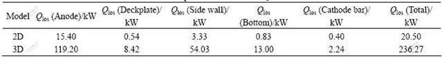
The full cell heat loss for the optimized lining is summarized in Table 2. Heat dissipation through the anode assembly (including the alumina cover) is as much as 119.20 kW. Heat loss though the side wall is as much as 54.03 kW. It can be reduced by adding a layer of heat insulation material. The full cell heat loss is 236.27 kW, which is very close to the theoretical loss of 238.60 kW where the current is 190 kA and CE is equal to 90%. So this kind of thermally working condition is seen as feasible. In this case the alumina cover is 16 cm thick with a thermal conductivity of 0.20 W/(m����). ACD is 2.5 cm and the anodic current density is 0.96 A/cm2. The electrolysis temperature is 946 ��.
Table 1 Components of heat equilibrium equation under various technical conditions (ACD=2.5 cm, tb=946 ��)
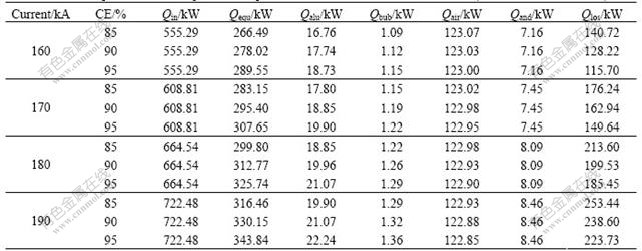
Table 2 Components of heat loss��tf=935 �棩
3.4 Discussion
Application of low temperature electrowinning technology can make the electrolysis temperature fall and thus save energy[18-20]. Graphitized carbon blocks are suitable to be used in this kind of cells at low electrolysis temperature because of its good electric and thermal conductivities. Research on inert cathode materials has advanced but the physically and chemically stable cathode structures with versatile sumps still need development.
Although the thermal inertia (for 3.5 t electrolyte and 10 t metal pad, change in thermal energy for 1 �� increase in temperature is approximately 6.19 MJ and 11.77 MJ, respectively) of the molten liquids is great, drained cells are more vulnerable to the surrounding changes caused by anode effects, alumina overfeed, anode changing, tapping and the room temperature because the aluminum pad is eliminated and the electrolyte is only about 20 cm high.
4 Conclusions
1) The calculated voltage for the system with experiential equations almost increases linearly with current increasing from 140 to 190 kA and anode- cathode distance from 2.5 to 4.5 cm.
2) The predicted ledge profile with a 2D FE model becomes thinner in a electrolysis temperature range from 944 to 950 ��. If the overheat decreases, the ledge is much close to the anode and can jam the interelectrode distance.
3) The theoretical heat dissipation is computed under various combinations of working parameters i.e. the anode-cathode distance, the current efficiency, the electrolysis temperature and the current. It was referenced by the mathematical model to find out the reasonable lining structure of drained cells.
4) Because energy losses by exhaled air from the hood and through the side wall account for 20% to 30% of the total heat loss, suitable air volume for ventilation and heat dissipation conditions near the side wall are of importance to the overall thermal balance of drained cells.
References
[1] STEDMAN I G, HOUSTON G J, SHAW, R W, et al. Aluminum smelting cells: US, 5043047[P]. 1991-08-27.
[2] TOWNSEND D W. Supersaturation plating of aluminum wettable cathode coatings during aluminum smelting in drained cathode cells: US, 5028301[P]. 1991-07-02.
[3] de NORA V. Cell for aluminum electrowinning employing a cathode cell bottom made of carbon blocks which have parallel channels therein: US, 5683559[P]. 1997-11-04.
[4] BERCLAZ G, de NORA V. Aluminum production cell and cathode: US, 6358393[P]. 2002-03-19.
[5] LI Qing-yu, LAI Yan-qing, LI Jie, et al. The effect of sodium-containing additives on the sodium-penetration resistance of TiB2/C composite cathode in aluminum electrolysis[C]// KVANDE H. TMS Light Metals. San Francisco: Minerals, Metals and Materials Society, 2005: 789-791.
[6] FENG Nai-xiang, QI Xi-quan, PENG Jian-ping, et al. Electrolysis test of 1350 A drained cathode reduction cell with TiB2-coated cathode[C]// GALLOWAY T J. TMS Light Metals. San Antonio: Minerals, Metals and Materials Society, 2006: 505-509.
[7] ZHOU Nai-jun, XIA Xiao-xia, BAO Sheng-zhong. Effect of electromagnetic force and anode gas on electrolyte flow in aluminum electrolysis cell[J]. Journal of Central South University of Technology, 2006, 13(5): 496-500.
[8] ZHOU Nai-jun, XIA Xiao-xia, WANG Fu-qiang. Numerical simulation on electrolyte flow field in 156 kA drained aluminum reduction cells[J]. Journal of Central South University of Technology, 2007, 14(1): 42-46.
[9] LI Xiang-peng, LI Jie, LAI Yan-qing, et al. Influences of gas discharging grooves at bottom of prebaked carbon anodes on bath flow pattern in aluminum reduction cells[J]. Chinese Journal of Nonferrous Metals, 2006, 16(6): 1088-1093. (in Chinese)
[10] ZHOU Nai-jun, MEI Chi, JIANG Chang-wei, et al. A method of determining and designing the drained slope in drained aluminum reduction cells[J]. Journal of Central South University of Technology, 2003, 10(1): 74-77.
[11] LI Xiang-peng, LI Jie, LAI Yan-qing, et al. Freeze profile heat balance calculation of the 160 kA drained cell[J]. Acta Metallurgica Sinica: English Letters, 2004, 17(2): 215-220.
[12] PEI Hai-ling, ZHOU Nai-jun, ZHOU Zheng-ming. Research on the performance of resisting heat disturbance of the drained cell[J]. Light Metals, 2005(3): 26-29. (in Chinese)
[13] YANG Zhong-yu. Light Metals Metallurgy[M]. Beijing: Metallurgical Industry Press, 1991. (in Chinese)
[14] ZHOU Ping. Continuously monitoring the shape of the ledge of aluminum electrolysis cells[D]. Changsha: Central South University, 1991. (in Chinese)
[15] HAUGLAND E, BORSET H, GIKLING H, et al. Effects of ambient temperature and ventilation on shell temperature, heat balance and side ledge of an alumina reduction cell[C]// GREPEAU P. TMS Light Metals. San Diego: Minerals, Metals and Materials Society, 2003: 269-276.
[16] HUO Qing-fa. Technologies and Equipments of the Aluminum Reduction Industry[M]. Shenyang: Liaohai Publishing House, 2002. (in Chinese)
[17] DUPUIS M. Thermo-electric analysis of the grande-baie aluminum reduction cell[C]// MANNWEILER U. TMS Light Metals. San Francisco: Minerals, Metals and Materials Society, 1994: 339-342.
[18] BROWN C W. Wettability of TiB2-based cathodes in low- temperature slurry-electrolyte reduction cells[J]. JOM, 1998, 50(5): 38-40.
[19] WELCH B J. Aluminum production paths in the new millennium[J]. JOM, 1999, 51(5): 24-28.
[20] KENIRY J. The economics of inert anodes and wettable cathodes for aluminum reduction cells[J]. JOM, 2001, 53(5): 43-47.
(Edited by YANG Hua)
Foundation item: Projects(50374081; 60634020) supported by the National Natural Science Foundation of China
Received date: 2007-03-02; Accepted date: 2007-04-28
Corresponding author: LIU Wei, Doctoral candidate; Tel: +86-731-8830474; E-mail: liuwei_csu@yahoo.com

