J. Cent. South Univ. (2012) 19: 1853-1858
DOI: 10.1007/s11771-012-1219-7
Dynamics of a novel bistable mechanism with mechanical-magnetic coupled structure
ZHAO Jian(�Խ�)1,2,3, HUANG Yu(��ع)2, YANG Yin-tang(������)3, GAO Ren-jing(���ʭZ)1,2
1. College of Automotive Engineering, Faculty of Vehicle Engineering and Mechanics,
Dalian University of Technology, Dalian 116024, China;
2. State Key Laboratory of Structural Analysis for Industrial Equipment
(Dalian University of Technology), Dalian 116024, China;
3. Key Laboratory of Wide Band-Gap Semiconductor Materials and Devices of Ministry of Education
(School of Microelectronics, Xidian University), Xi��an 710071, China;
? Central South University Press and Springer-Verlag Berlin Heidelberg 2012
Abstract: Bistable mechanisms are very appealing in the design of valves, switches and actuators. By utilizing the nonlinear magnetic structure and elastic cantilevers, a novel bistable mechanism was designed. Based on the magnetic charge model and material mechanics theory, the nonlinear force during the snap-through procedure was calculated accurately, which is in accordance with that obtained by the experiments. In addition, the bistable characteristics including the threshold snapping force, the traveling range, and stable positions can be adjusted by changing the structure parameters and the relative distance among the magnets. The dynamic analysis shows that the bistable structure has a good frequency distinguishing capacity for mechanical shock pulses.
Key words: bistable mechanism; coupled structure, nonlinearity; dynamics
1 Introduction
A bistable mechanism mainly has two stable states where no input power is required to maintain its position and the input energy is only required to change from one stable point to another. Up to now, four main categories of bistable mechanisms have been reported: latch-lock mechanisms [1], hinged multisegment mechanisms or compliant bistable mechanisms [2-9], residual compressive-stress buckled-beams [10-14], and double slider mechanisms [15-16]. HOFFMANN et al [1] designed a bistable optical switch with thermo-actuator by using the bulk silicon micromachining. The bistable operation was achieved by the movement of the input fiber between the two V-grooves etched in the fixed fiber. Unfortunately, the friction is the most important challenging factor affecting the positioning accuracy. With the deepened research on the compliant mechanisms, HOWELL et al [4-9, 15] and TSAY et al [16] designed many kinds of compliant bistable mechanisms by using large deflection beams, double sliders and flexural pivots to avoid the friction problems. SAIF [10] and ZHAO et al [14] also designed bistable mechanisms by utilizing the absorption and release of the deformation energy of the buckling and post-buckling beams. However, there is also another problem for adjusting the stable positions and the threshold snapping force in the four bistable mechanisms mentioned above. For example, once the configurations of the latch-lock mechanism and buckling beams with two ends fixed are assigned to be fixed, it is difficult to move the stable positions or regulate the magnitude of the residual stress.
Besides the explored bistable mechanisms mentioned above, a novel magnetic actuated bistable structure with three magnets fixed in the three dimensional space is proposed in this work. And the bistability of such structure is analyzed based on the magnetic-charge model as well. The most attractive thing is that there is a force holding period during the snap-through procedure, and the traveling range, the stable positions, and the value of elastic reaction force at the stable positions can be adjusted freely by changing the magnet parameters and the relative distance among the three magnets. As a consequence, the magnetic actuated bistable structure is an ideal spring element in designing an adjustable threshold acceleration switch, whose threshold acceleration can be tuned in a wide range for special applications.
2 Bistable permanent magnetic structure
Bistable mechanisms provide several benefits, including backlash-free, wear-free, and friction-free operation. Compared with the linear elastic structure, the bistable structure not only has the advantage of precise location, small size, low power consumption, and low products cost, but also has the snap-through phenomena which can improve the response speed of the devices. Because of the advantages they offer, the bistable mechanisms are widely used in many devices such as switches, valves, clasps, and closures which need to be kept in one of the states for a prolonged period of time and to define precisely two statically stable states.
Conventionally, the bistability is often produced by the following means:
1) Using the deformation of the mechanical structures such as flexible beams, buckled beams, hinges with zero frictions;
2) Utilizing the complex actuated latch-lock structures such as hooks or grooves;
3) Introduction of the electrostatic forces, electromagnetic forces, or thermal forces.
With the improvement of the stability of the permanent magnetic products, magnets are widely introduced in designing electrical or mechatronical equipments. By utilizing the nonlinearity of the permanent magnetic force, an adjustable bistable structure with three permanent magnets arranged in a three-dimensional case is designed, as shown in Fig. 1.
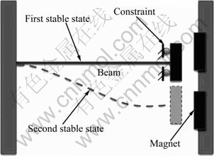
Fig. 1 Bistable structure with three magnets
In Fig. 1, there is an orientation constraint on the moving magnet to keep the distance between the moving part and the fixed magnets unchanged while the stable position changes. Based on the theory of material mechanics [17] and the beam boundary conditions, the expression of the elastic force Fk of the beam can be deduced as follows:
 (1)
(1)
where E is the modulus of elasticity, l is the length of the beam, x is the displacement of the beam end, and I is the moment of inertia.
In Fig. 2, the three magnets have the same magnetization direction, magnetization intensity J, and geometrical size 2a��2c��2b. When it moves along the positive x direction, the moving magnet is subjected to the resultant magnetic force from the other two fixed magnets. During the movement, the two different relative coordinates of the central position of the moving magnet relative to the fixed magnet 1 and magnet 2 are (��1, ��1, ��1) and (��2, ��2, ��2). The relation between the two relative positions can be expressed as ��2=L-��1, ��2= ��1, ��2= ��1.

Fig. 2 Three magnets arranged in three dimensional space
Based on the magnetic-charge model [18-19] and the superposition principle of magnetic force, the total magnetic force applied by the two fixed magnets along the x direction can be obtained:

 (2)
(2)
where n is the number of the fixed magnets, rn is the distance between the two interactive magnets, and ��0 is the magnetic permeability. The intermediate variables in Eq. (2) are
 (3)
(3)
Assume that in Fig. 2 the central parts of the moving magnet and the fixed magnet 1 are all at the z axis, and there is no displacement in the y and z directions. Therefore, the total force can be expressed as
 (4)
(4)
where Fk is the linear elastic force of the cantilever, and Fm is the magnetic force.
According to the structural parameters in Table 1 and Table 2, a sample of the bistable structure is fabricated, as shown in Fig. 3, which mainly consists of a parallel beam combined with three magnets arranged in the three-dimensional space. And the threshold snapping force is measured by the electrical tensile and compression testing machine.
Table 1 Parameters of parallel beam

Table 2 Parameters of magnet
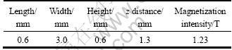

Fig. 3 Bistable parallel structure with three magnets
In Fig. 4, the electronic digital spring tester (SD-10 Sundoo Instruments Co. Ltd.) mainly consists of a displacement transducer, a force sensor, and two output screens. The load and distortion resolution of the digital tester are 0.001 N and 0.01 mm. The tristable magnetic structure is fixed on the supporting platform when the vertical force from the probe is applied to the moving magnet. When the gauge moves, the displacement and the corresponding reaction force can be sensed and displayed on the two different output screens, respectively.
By introducing the nonlinear magnetic force, the linear cantilever becomes a nonlinear bistable structure with threshold snapping characteristic. Figure 5 shows the variation of total force with the displacement for the magnetic bistable structure, which is consistent with that from the experiments in Fig. 4.
The combined effect of the magnetic force and elastic force on the bistability of the whole structure is investigated. Based on the energy variation principle, the curve of the total force expresses the first-order derivative of the whole system energy. Along the curve of the total force, there are only three points where the force equals zero. And two points including the first stable point and the second combined stable point can fulfill the stability requirement that the second derivate of system energy must be greater than zero. Consequently, according to the energy analysis above, the constraint magnetic beam structure in Fig. 1 has the unsymmetrical bistable characteristic, which means that the absolute value of the total force in the positive direction is greater than that in the negative direction. And also, the direction of the elastic force changes when the structure snaps through the unstable balanced point to the other stable state. Therefore, the bistability performed by the combined structure is suitable for designing the novel threshold switch.

Fig. 4 Experiment set for combined magnetic force

Fig. 5 Force variation during snap-through process
3 Influence of magnet parameters on bistability
When the parameters of the parallel beam and the distance between the fixed magnets remain constant, the threshold snapping force and the second stable position change with the magnet parameters. Assuming that all the three magnets are in the same size, the effects of the magnet parameters on the bistability are shown in Figs. 6-8. In the three figures, the shapes of the combined total force are unsymmetrical because of the action of the linear elastic force of the cantilever.

Fig. 6 Effect of magnet length on bistability (L, w and h represent length, width and height of moving magnet)
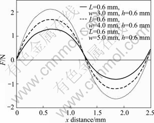
Fig. 7 Effect of magnet width on bistability (L, w and h represent length, width and height of magnet; Traveling range is 2.5 mm)
Figure 6 shows the variation of the combined total force with the length of the moving magnet. The traveling range and the threshold snapping force of the bistable structure increase with the magnet length. Between the two stable states, there is only one unstable state, where the direction of the total force changes.
In Fig. 7, when the magnet width increases, the threshold snapping force increases obviously. Variation of the magnet width does not affect the other bistable characteristics too much. The stable positions and traveling range only change in a very small domain.
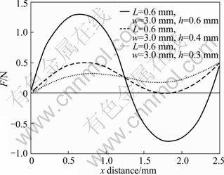
Fig. 8 Effect of magnet height on bistability (L, w and h represent length, width and height of magnet; Traveling range is 2.5 mm)
In Fig. 8, we can see that the height of the magnet plays an important role in producing the bistability. When the magnet height diminishes to a certain value, the combined force at the second stable position becomes positive and there should be an additional force to keep the structure in the second stable state. For instance, when the magnet height is smaller than 0.4 mm, the bistability of the structure disappears, and the second stable state changes into the local stable state, which means that in the whole traveling range, there is only one stable state at the original position.
Figure 9 shows the variation of the threshold snapping force with the distance between the two fixed magnets. When the dimensional parameters of the magnet remain unchanged, the threshold snapping force increases with the distance between the two fixed magnets, and so does the traveling range of the bistable structure. In fact, the elastic force increases linearly with the displacement of the moving magnet. Known from Eq. (4), the combined force is the sum of the magnetic force and the elastic force. So, the threshold snapping force increases proportional to the displacement of the moving magnets. Meanwhile, the slope of the curve represents the changing speed of the total force. With other parameters being unchanged, when the magnitude of the slope becomes larger, the bistable structure snaps faster.
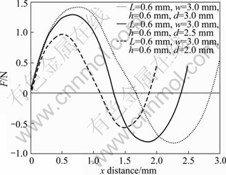
Fig. 9 Effect of traveling range on bistability (L, w, h and d represent magnet length, magnet width, magnet height and distance between two fixed magnets)
Another interesting phenomenon of the proposed bistable structure is that a force holding period occurs during the snap-through procedure. Supposing that the parameters of the parallel beam and the three magnets keep unchanged, when the distance between the two fixed magnets is larger than 5 mm, the combined force remains at a constant value when the moving magnet moves in a certain traveling range, which means that the structure will stay at any position of that traveling range if the applied force is no larger than that constant value, as shown in Fig. 10.
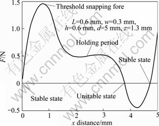
Fig. 10 Holding period during snap-through procedure
4 Dynamic response of bistable structure
Another important characteristic is the snapping speed of the bistable structure, which can improve the responsibility of the device significantly. In order to analyze the snap-through procedure systematically, the dynamic model must be established first.
Ignoring the mass of the parallel beam itself and considering the nonlinear magnetic force, elastic force and gas film damping, the dynamic equilibrium of the bistable structure can be written as the equation of motion in the form of a single degree-of-freedom oscillator:
 (5)
(5)
where m represents the mass, c is the damping coefficient, Fm is the magnetic force, and Fa is the harmonic force applied. Parameter c is the damping coefficient which is mainly due to the viscous effects of the air between the mass and the substrate.
Based on the reduced Reynolds�� equation, the gas film damping coefficient can be obtained, which is a function of the mass position [20-22]:
 (6)
(6)
where ��eff represents the equivalent viscosity, a0 and b0 are the height and width of the inertial mass, respectively, and d0 is the initial distance between the mass and the substrate.
In Fig. 11, the time response of the bistable structure for the half-sine pulse force is obtained from the numerical simulation. The total response time is nearly 19 ms, and the time used to snap-through is only 8 ms. When the applied force exceeds a critical maximum value and the moving magnet moves over a certain position, the bistable structure operates and snaps fast to the other stable state.

Fig. 11 Time response for half-sine pulse
To analyze the amplitude frequency characteristic of the bistable structure, a mini vibration test bench is established, which consists mainly of a vibration exciter, a charge amplifier, an oscillograph, and a detecting circuit, as shown in Fig. 12. The testing results show that the bistable structure has a good capacity of distinguishing mechanical shock pulses, as shown in Fig. 13. When the applied frequency is larger than the resonant frequency of the bistable structure, the applied harmonic force must be much larger than the critical force to switch the stable states. With the input frequency ��i=��n, the resonance of the system occurs, and the harmonic force applied is close to the critical force to switch the states. While the input frequency ��i<<��n, the amplitude of the harmonic force that the system can bear is larger than the critical switching force that the bistable structure has. In addition, the mechanical shock distinguishing capability of the bistable structure increases with the damping coefficient.
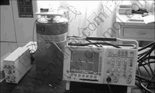
Fig. 12 Vibration testing bench

Fig. 13 Amplitude frequency characteristic of switch
5 Conclusions
1) A novel unsymmetrical bistable mechanism is proposed by introducing the combined effect of permanent magnets and linear mechanical structure. The bistability of such bistable structure is analyzed based on the magnetic-charge model and material mechanics theory. The combined force curve of a bistable structure has two or more parts in which the structure is stable, separated by unstable regions or sometimes added by a force holding region.
2) According to the analysis of the influence factors on the bistablility, the bistable characteristics can be adjusted freely by changing the corresponding parameters or relative spacial positions. For example, the time for snap-through can be adjusted by changing the relative distances among the three magnets. In addition, the proposed structure has a very good mechanical shock distinguishing capability, which is very important in the application of the vibration isolation, energy absorption, and threshold acceleration sensing.
References
[1] HOFFMANN M, KOPKA P, VOGES E. All-silicon bistable micromechanical fiber switch based on advanced bulk micromachining [J]. IEEE J Sel Top Quant, 1999, 5(1): 46-51.
[2] KRUGLICK E J, PISTER S J. Bistable MEMS relays and contact characterization [C]// Proc IEEE Solid-State Sens Actuator Workshop. Hilton Head Island, South Carolia: IEEE Transducer Research Foundation Inc, 1998: 333-337.
[3] JENSEN B D. Identification of macro- and micro-compliant mechanism configurations resulting in bistable behavior [D]. Provo: UT Brigham Young Univ, 1998.
[4] MASTERS N D, HOWELL L L. A self-retracting fully compliant bistable micromechanism [J]. J Microelectromech Syst, 2003, 12(3): 273-280.
[5] HOWELL L L, RAO S S, MIDHA A. The reliability-based optimal design of a bistable compliant mechanism [J]. ASME J Mech Des, 1994, 116(4): 1115-1121.
[6] OPDAHL P G, JENSEN B D, HOWELL L L. An investigation into compliant bistable mechanisms [C]// Proc ASME Design Engineering Technical Conferences. Atlanta: ASME Conference, 1998: 1-10.
[7] BAKER M S, HOWELL L L. On-chip actuation of an in-plane compliant bistable micro-mechanism [J]. J Microelectromech Syst, 2002, 11(5): 566-573.
[8] HOWELL L L, MIDHA A. a method for the design of compliant mechanisms with small-length flexural pivots [J]. ASME J Mech Des, 1994, 116(1): 280-290.
[9] HOWELL L L, MIDHA A. Parametric deflection approximations for end-loaded, large-deflection beams in compliant mechanisms [J]. ASME J Mech Des, 1995, 117(1): 156-165.
[10] SAIF M T A. On a tunable bistable MEMS-Theory and experiment [J]. J Microelectromech Syst, 2000, 9(2): 157-170.
[11] HALG B. On a micro-electro-mechanical nonvolatile memory cell [J]. IEEE Transactions on Electron Devices, 1990, 37(10): 172-176.
[12] BUCHAILLOT L, MILLET O, QUEVY E, COLLARD D. Post-Buckling dynamic behavior of self-assembled 3D microstructures [J]. Microsyst Technol, 2007, 14(1): 69-78.
[13] MICHAEL A, KWOK C Y. Buckling shape of elastically constrained multi-layered micro-bridges [J]. Sens Actuators A: Phys, 2007, 135(1): 870-880.
[14] ZHAO Jian, JIA Jian-yuan, WANG Hong-xi. Post-buckling and snap-through behavior of inclined slender mirobeams [J]. Journal of Applied Mechannics Transactions of the ASME, 2008, 75(4): 201-207.
[15] JENSEN B D, HOWELL L L. Bistable configurations of compliant mechanisms modeled using four links and translational joints [J]. Journal of Mechanical Design Transactions of the ASME, 2004, 126(4): 657-666.
[16] TSAY J, SU L Q, SUNG C K. Design of a linear micro-feeding system featuring bistable mechanisms [J]. J Micromech Microeng, 2005, 14(1): 63-70.
[17] TIMOSHENKO S P, GOODIER J N. Theory of elasticity [J]. 3rd ed. New York: McGraw Hill, 1970: 89-495.
[18] YONNET J P, HEMMERLIN S. Analytical calculation of permanent magnet couplings [J]. IEEE Trans Magn, 1993, 29(6): 2932-2934.
[19] AKOUN G, YONNET J. 3D analytical calculation of the forces exerted between two cuboidal magnets [J]. IEEE Trans Magn, 1984, 20(5): 1962-1964.
[20] KAMPEN P V, WOLFFENBUTTEL R F. Modeling the mechanical behavior of bulk-micromachined silicon accelerometers [J]. Sens Actuators A: Phys, 1998, 64: 137-150.
[21] GRIFFIN W S, RICHARDSON H H, YAMANAMI S. A study of fluid squeeze-film damping [J]. Trans ASME J Basic Eng, 1966: 451-456.
[22] BAO M. Micromechanical transducers: Pressure sensors, accelerometers and gyroscopes [M]. New York: Elsevier, 2000: 10-25.
(Edited by YANG Bing)
Foundation item: Project(51105059) supported by the National Natural Science Foundation of China; Project(20100041120019) supported by the Doctoral Fund of Ministry of Education of China; Project(2011CB610304) supported by the National Basic Research Program of China; Project(60725415) supported by the National Natural Science Foundation of China for Distinguished Young Scholars; Project(201003665) supported by the Fundamental Research Funds for the Central Universities of China
Received date: 2011-05-10; Accepted date: 2011-06-30
Corresponding author: ZHAO Jian, PhD; Tel: +86-411-84706760-8308; E-mail: jzhao@dlut.edu.cn

