J. Cent. South Univ. Technol. (2009) 16: 0697-0701
DOI: 10.1007/s11771-009-0115-2

Design and dynamic simulation of hydraulic system of a new automatic transmission
WANG Shu-han(���麲)1, XU Xiang-yang(������)1, LIU Yan-fang(����)1,
DAI Zhen-kun(������)1, TENBERGE P2, QU Wei(�� Ρ)2
(1. School of Transportation Science and Engineering, Beijing University of Aeronautics and Astronautics,
Beijing 100083, China;
2. Institute for Engineering Design and Powertrain Technologies, Chemnitz University of Technology,
Chemnitz 09107, Germany)
Abstract: A new hydraulic system of a novel automatic transmission (AT) was designed. The dimension and structure of valves and cylinders were designed by theoretical calculation. The dynamic simulation model of hydraulic system of AT was established by ITI-SimulationX. Simulation results and theoretical design results were compared to confirm the simulation model. Based on the confirmed simulation model, the simulation results of pressure and flow of the hydraulic system were analyzed. The dynamic simulation method is very helpful for designing and analyzing the performance of hydraulic system and further optimization design. The theoretical design method and dynamic simulation model are feasible for the real industrial applications. The research results can be used in hydraulic system design and optimization.
Key words: automatic transmission; hydraulic system; dynamic simulation
1 Introduction
The hydraulic system of automatic transmission (AT) is a very important part of the powertrain. Its function is to ensure normal work of transmission system, to control shifting and the shifting process of transmission system [1-2]. To match the characteristics of oil pressure and volume flow can not only prolong the working life of shift elements and AT, but also effectively decrease the power loss of the shifting process to ensure the acceleration performance of the car, as well ensure the quality of shifting [3]. By analyzing the dynamic process of hydraulic system, every kinematic and kinetic process of each element in the hydraulic system can be known [4].
The dynamic simulation of hydraulic system of AT and optimization of main parameters were mainly presented in Refs.[1-3]. But these references do not describe how to design hydraulic system of AT. OSHIMA et al [4] and MIYATA et al [5] presented improved solution of hydraulic system of AT briefly, which did not include the detailed design and simulation conclusions. MA [6] and FENG et al [7] studied the dynamic characteristics of power shift clutch in charge process. They only considered one clutch in AT, and did not consider shift process of the whole hydraulic system of AT. PAN and MOSKWA [8], MARTIN et al [9], OHASHI et al [10], and YANG and HE [11] presented the whole AT, and introduced the functions of hydraulic system of AT simply. LEE et al [12], JIANG et al [13], and LI et al [14] investigated optimization and improvement of special valve in hydraulic system of AT, but the whole hydraulic system was not simulated. According to the previous references, it can be concluded that the design method and process of hydraulic system of AT are not perfect technologies. The hydraulic system of AT designed needs to be optimized and modified step by step. Static design plays a main role. The dynamic simulation will be done after the production is designed, long development period and high development cost. In this work, a new design method of hydraulic system of AT was discussed. The more excellent hydraulic system of AT would be exploited in short period by the whole design and dynamic simulation for hydraulic system of AT.
2 Design and operating principle of hydraulic system
Table 1 lists the shifting logic of the transmission. There are only five shifting elements realizing eight well stepped forward gears and one reverse gear. As shown in Fig.1, five solenoid valves that control five shifting elements are electronic proportional control valves (EPCV). One EPCV controls close pressure of one shifting element. Pure electronic pressure control is used in the hydraulic system. Pressure is controlled by transmission control unit (TCU) based on the engine torque output. Quick response and high quality shift are realized by using solenoid to control every shifting element individually.
Table 1 Shifting logic of transmission

Manual valves are moved to the right position by pressure in pipe ��X��. The adjustable pressure can operate shifting elements when the manual valves are on the position. When EPCV goes to fail, the pressure will disappear in pipe ��X��. Manual valves will be moved to the left position because of spring force. Shifting pressure is controlled by manual shifting valve (MSV) at this position. If anyone of EPCV of five control elements goes to fail, all of EPCV will be closed, and the emergency procedure will be started up.
Shift lever connects with MSV. When shift lever is on the R gear, shifting elements of B1, K2 and K4 will be closed. When shift lever is on the N gear, only shifting elements of K2 and K4 will be closed. When shift lever
is on D gear which can only be 5-gear, shifting elements of K1, K2 and K4 will be closed, which is also called as ��Limp home�� gear.
The pressure in pipe ��g�� is decreased as 0.5 MPa by pressure reducing valve (prv_gq), which is used to open shifting elements. The cylinder of brake (B1) is opened using disc spring.
3 Dynamic simulation model of hydraulic system
3.1 Mathematic method
Flow description of valves edge and orifice in Fig.1 is
 (1)
(1)
where �� is flow coefficient, A is cross section area, ��p is pressure loss, and �� is flow density.
Flow of the plunger cylinder is determined by the piston area AA, the piston velocity vpiston as well as the external leakage flow QleA:
 (2)
(2)
Flow at ports A and B of the differential cylinder is determined by the piston areas AA and AB, the piston velocity vpiston as well as the internal and external leakage flow Qli and QleA:
 (3)
(3)
3.2 Simulation model
According to the model in Ref.[1] and static calculation results using MATHCAD, the dynamic simulation model was established. ITI-SimulationX is a dynamic simulation software from ITI GmbH which is used to build the model of hydraulic system of AT.

Fig.1 Schematic diagram of shifting hydraulic system of AT
3.3 Simulation parameters
The main oil pressure in the hydraulic system was offered by constant flow pump. System temperature was from -30 to 150 ��, the main oil pressure was 0.8-2.0 MPa, the rotational speed of pump was 0-5 700 r/min, and the displacement was 0.01 L/r which was 70% of ideal displacement.
The simulation results at the changing rotational speed and lockup time would be displayed. Meanwhile, temperature was set as 90 ��, and gear was set according to increasing gear in sequence. The change of parameters is shown in Figs.2 and 3. Table 2 lists the parameters of every control unit.

Fig.2 Relationship between rotational speed of pump and time

Fig.3 Relationship between lockup ratio and lockup time
4 Analysis of simulation results
4.1 Comparing static results and dynamic results
The main pressure which is controlled by pressure reducing valve (prv_pg) of hydraulic system is between 0.8 and 2.0 MPa. The control pressure of prv_pg is supplied by solenoid valve named EPCV_g. Pressure entering shifting cylinder is controlled by every EPCV_C of shifting elements.
Table 2 Parameters of control units

As shown in Fig.4, it can be seen that the dynamic simulation results ITI-SimulationX well agree with the calculation results in Mathcad, and the tolerance controls within 5%. The dynamic changing of flow force of valve��s edge is the main reason for the tolerance. Prv_pg can control the main pressure between 0.8 and 2.0 MPa well from the dynamic and static results. This confirms that the clutch friction plates cannot be slipped in the every work condition. The main pressure should be decreased possibly, in order to decrease the pressure of friction plates and prolong the natural life of the clutch. The same method was also used for every valve in the hydraulic system of AT, which confirmed the correctness of every valve. The whole dynamic simulation would be done after every valve met the design requirement.

Fig.4 Comparison of static calculation with dynamic simulation of prv_pg
4.2 Analysis of dynamic results
As shown in Fig.5, when the shifting element was closed, the adjustable pressure was kept between 1.7 and 2.0 MPa. Pressure drop of C1 was observed clearly. Meanwhile, C1 was opened. Then pressure increase of C2 led to close of C2. Time for closing C2 was about 0.4 s. There were three stages in the oil-filled process of C2: (1) stage of the rapid oil-filled, (2) stage of gas elimination of cylinder and clutch, and (3) stage of pressure increasing rapidly. According to dynamic analysis, shifting pressure and shifting process satisfied design requirement.

Fig.5 Dynamic pressure of every cylinder from 3-gear to 4-gear
The relationship between oil-filled flow of C2 and oil-released flow of C1 could be observed clearly from Fig.6. According to dynamic analysis, when shifting, the flow which entered high pressure circuit (line ��g��) could fill cylinder rapidly. The required flow satisfied design requirement. Also the oil-released cylinder could release oil rapidly to separate shifting element.

Fig.6 Dynamic flow of every cylinder from 3-gear to 4-gear
4.3 Analysis of main dynamic parameters
Changing the spring stiffness of syspv was equivalent to changing the minimum opening pressure. As shown in Fig.7, dynamic flow of main circuit greatly changed when the opening pressure was 0.15-0.18 MPa. Dynamic flow of main circuit could directly affect AT acceleration performance, shift quality and AT cooling and lubrication. Fitting spring stiffness was helpful to improve the performance of hydraulic system of AT.
The main parameters could be adjusted to satisfy the design criteria of hydraulic system of AT by simulation.
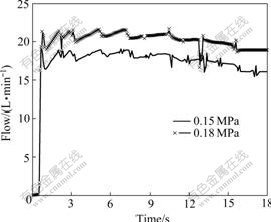
Fig.7 Dynamic flow of main circuit with changing of spring stiffness of syspv
5 Conclusions
(1) A new design of hydraulic system of AT is presented by analysis of the shift logic and shift characteristic.
(2) The dynamic model of every valve is simulated by ITI-SimulationX software. The dynamic results are compared with the static results. The tolerance is controlled within 5%. Then the whole dynamic simulation model is established. Dynamic characteristic of pressure and flow are analyzed. The parameters of system elements which affect the system pressure and flow are analyzed.
(3) Next step, the basic machine will be assembled. Bench test will be done to test the correctness of hydraulic system of AT. The control strategy will be put forward to compile TCU control program.
References
[1] WANG Shu-han, XU Xiang-yang, LIU Yang-fang, DAI Zhen-kun. Dynamic characteristic simulation of AT hydraulic system [C]// 2008 SAE World Congress. Shanghai, 2008: 2008-01-1683.
[2] SOHL G A, BOBROW J E. Experiment and simulation on the nonlinear control of a hydraulic servosystem [J]. IEEE Transactions on Control systems Technology, 2006, 7(1): 238-247.
[3] MEGLI T W, HAGHGOOIE M, COLVIN D S. Shift characteristics of a 4-speed automatic transmission [C]// JURGEN R K. Electronic Transmission Controls. Warrendale: Society of Automotive Engineers Inc, 2000: 277-289.
[4] OSHIMA K, KIMURA H, MIYATA H, MATSUMOTO S. Control system development with large flow small linear solenoid for a new Toyota FWD 6-speed transaxle [C]// 2006 SAE World Congress. Detroit: Transmission and Driveline of SAE, 2006: 2006-01-1487.
[5] MIYATA H, HOJO Y, TABATA A. Toyota new compact five-speed automatic transmission for RWD passenger cars [C]// JURGEN R K. Electronic Transmission Controls. Warrendale: Society of Automotive Engineers Inc, 2000: 35-43.
[6] MA Biao. Influence cushioning pressure characteristics on shift clutch engagement process [J]. Journal of Beijing Institute of Technology, 2000, 9(4): 362-369.
[7] FENG Neng-lian, ZHENG Mu-qiao, MA Biao. Dynamic performance simulation of power shift clutch during shift [J]. Journal of Beijing Institute of Technology, 2004, 13(4): 445-450.
[8] PAN C H, MOSKWA J J. Dynamic modeling and simulation of the ford AOD automobile transmission [C]// JURGEN R K. Electronic Transmission Controls. Warrendale: Society of Automotive Engineers Inc, 2000: 111-120.
[9] MARTIN B, REDINGER C J, DOURRA H. Chrysler 45RFE: A new generation real-time electronic control RWD automatic transmission [C]// JURGEN R K. Electronic Transmission Controls. Warrendale: Society of Automotive Engineers Inc, 2000: 3-23.
[10] OHASHI T, ASATSUKE S, MORIYA H. Honda��s 4 speed all clutch to clutch automatic transmission [C]// JURGEN R K. Electronic Transmission Controls. Warrendale: Society of Automotive Engineers Inc, 2000: 45-53.
[11] YANG Zhong-jiong, HE Qing-hua. Simulation of dynamic characteristics of hydraulic power steering system of articulated vehicles [J]. Journal of Central South University: Science and Technology, 2004, 35(1): 80-85. (in Chinese)
[12] LEE H W, CHO B H, LEE W H. A study on response improvement of proportional control solenoid valve for automatic transmission [C]// JURGEN R K. Electronic Transmission Controls. Warrendale: Society of Automotive Engineers Inc, 2000: 463-468.
[13] JIANG Bing-yan, XIE Lei, TAN Xiao-feng, LIU Shi-qiang. Influence of section shape of micro channels on microfluid flowability [J]. Journal of Central South University: Science and Technology, 2006, 37(5): 964-969. (in Chinese)
[14] LI Yong-tang, LEI Bu-fang, TING Kwun-lon. ��GRAY-BOX�� modeling method and parameters identification for large-scale hydraulic system [J]. Chinese Journal of Mechanical Engineering, 2003, 16(1): 1-3. (in Chinese)
(Edited by YANG You-ping)
Foundation item: Project(911901204) supported by Youth Innovation Foundation of Beijing University of Aeronautics and Astronautics
Received date: 2008-09-28; Accepted date: 2008-11-06
Corresponding author: WANG Shu-han, Doctoral candidate; Tel: +86-10-82338121; E-mail: buaawsh@hotmail.com

