
Mechanism of electro-generating leaching of chalcopyrite-MnO2 in presence of Acidithiobacillus thiooxidans
XIAO Li(肖 利)1, 2, LIU Jian-she(柳建设)3, FANG Zheng(方 正)1, QIU Guan-zhou(邱冠周)4
1. School of Chemistry and Chemical Engineering, Central South University, Changsha 410083,China;
2. Metallurgical Engineering College, Hunan Industrial University, Zhuzhou 412000, China
3. College of Environment Science and Technology, Donghua University, Shanghai 201620, China;
4. School of Minerals Processing and Bioengineering, Central South University, Changsha 410083, China
Received 20 September 2008; accepted 5 November 2008
Abstract: A dual cell system with chalcopyrite anode and MnO2 cathode was used to study the relations between time and such data as the electric quantity and the dissolution rates of the two minerals in the electro-generating leaching(EGL) and the bio-electro-generating leaching(BEGL), respectively. The results showed that the dissolution rates for Cu2+ and Fe2+ in BEGL were almost 2 times faster than those in EGL, and nearly 3 times for Mn2+; the electric output increased nearly by 3 times. The oxidation residue of chalcopyrite was represented by TEM and XRD, whose pattern was similar to that of the raw ore in EGL. The mechanism for leaching of CuFeS2-MnO2 in the presence of Acidithiobacillus thiooxidans was proposed as a successive reaction of two independent sub-processes for the anode. The first stage, common to both processes, is dissolution of chalcopyrite to produce Cu2+, Fe2+ and sulfur. The second stage is subsequent oxidization of sulfur only in BEGL, which is the controlling step of the process. However, the dissolution of MnO2 lasts until the reaction of chalcopyrite stops or the ores exhaust in two types of leaching.
Key words: chalcopyrite; MnO2; bio-oxidation; electro-generative leaching
1 Introduction
The electro-generating leaching(EGL)[1-3] has been applied to sulfides. In the process, substantively, the Gibss free energy is transformed to an applicable electrical work[4] and the products are simultaneously leached. In order to complete EGL, a galvanic cell with anolyte and catholyte rooms separated by an anion membrane which allows anions to migrate freely is designed[3-6]. The compact sulfide powder and MnO2 powder are used as the anode and cathode, respectively. The new technique not only can simplify the purification of the leached solution, but also can produce element sulfur instead of gaseous H2S[7] and SO2[8] that pollute environment in the traditional leaching.
There are some reports on hydrometallurgical treatment of the chalcopyrite minerals[3,9-14], including EGL of CuFeS2-MnO2[3, 9]. XIAO et al[9] have pointed out that sulfur produced in EGL covers the surface of the leached sulfides, thwarting anodic reaction taking place more and greatly reducing the electric energy output. The rates of corrosion of the two minerals in EGL were much higher than their self-corrosion rates[10-11]. It is also shown[12] that the sulfur film covered on the mineral surface passivated the anode. TAKAMI et al[15] presented that the elemental sulfur could be removed by the Acidithiobacillus ferrooxidans (A. ferrooxidans) in EGL of ZnS- MnO2.
A. thiooxidans plays an important role in the biochemical treatment of sulfur[16-17]. The bacteria can obtain energy from oxidation of sulfur substrate[18-19] and make covered sulfur on the surface of minerals oxidized and removed. However, little work on leaching of chalcopyrite in the presence of A. thiooxidans is reported, especially the mechanism of bio-oxidization for the mineral is still indistinct.
In this study, the authors aim to explore the mechanism of BEGL for CuFeS2 in the presence of A. thiooxidans by analysis of the relations between time and such data as the electric quantity and the dissolution rate of Cu2+, Fe2+, and Mn2+ in a galvanic cell with A.thiooxi-dans,and by the evidence of SEM and XRD for oxidation remains of the mineral.
2 Experimental
2.1 Minerals
Chalcopyrite with 75 μm in size was naturally hand- sorted from a domestic mine. The XRD analysis shows that CuFeS2 is predominant, and PbS and SiO2 coexist. The results of element analysis are listed in Table 1. Manganese dioxide was commercial reagent (Shanghai Chemical Regents Industries, Ltd., China).
Table 1 Chemical composition of chalcopyrite (mass fraction, %)

2.2 Set and electrode for EGL
The cell frame placed in water bath was made of PVC, which was divided into anolyte and catholyte compartments, each of 200 mL, connected by an anion membrane, as shown in Fig.1. The membrane allowed anions to migrate freely[5-6], and blocked up cations.
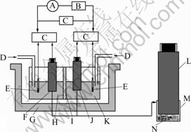
Fig.1 Schematic diagram of experimental apparatus: A― Amperemeter; B―Variable resistor; C―PHS-3C digital acidometer; D―Air-blowing tube; E―Saturated calomel electrode; F―Anode; G―Isothermal water bath; H―Anolyte; I―Anion membrane; J―Cathode; K―Catholyte; L―Carbon pole; M―Filtering cloth; N―Concentrate powder (chalcopyrite or MnO2)
Two electrodes are made of the powders of chalcopyrite and MnO2, respectively. Air-blowing tubes were separately inserted into the anolyte and catholyte rooms to agitate and to supply oxygen for bacteria. The pH value, electrode potentials (vs SCE) and output voltage of the cell were measured with a PHS-3C digital acidometer, the output current with an amperemeter and the concentration of oxygen with a Degussa oxygen meter. All of the measured instruments were calibrated before each run.
2.3 Solutions and bacteria
The solutions were prepared using AR reagents and distilled water. The bacteria culture medium consisted of (NH4)2SO4 3.0 g/L, KCl 0.1 g/L, K2HPO4 0.5 g/L, MgSO4?7H2SO4 0.5 g/L and Ca(NO3)2 0.01 g/L. For comparison, the medium was acidified first to pH 1.8 by H2SO4 as the anolyte of EGL, and the same nutrient medium with exponential growth phase bacteria was used as the anolyte of BEGL. Oxygen in the solution was 5.9 mg/L. A pure strain of A. thiooxidans that could breed on chalcopyrite was from Hubei Province of China.
3 Results and discussion
3.1 Relations between electric quantity, dissolved metal ion rate and time
Each run was started under open-circuit, and the measurement of electric output was under the closed- circuit with 8 Ω load, which corresponds to the maximum power output[6]. The relation between the measured electric quantity(MEQ) and time is almost linear in EGL and BEGL, as shown in Fig.2. The fitting equations and correlation coefficient R are as follows:
Q(EGL)=17.36+0.797t, R=0.998
and
Q(BEGL)=30.74+0.915t, R=0.999

Fig.2 Relations between MEQ and time for 12 h in EGL and BEGL
From the slopes of straight lines it can be seen that A. thiooxidans accelerates the oxidation of ores, resulting in the increase of MEQ. But the advantage is unremarkable in 12 h.
As well known, 1 mol CuFeS2, theoretically, produces 1 mol Cu2+, 1 mol Fe2+ and 2 mol S0 in disorganization. Accordingly, it is reasonable to consider the total element sulfur n(S0) generated amounts to the dissolved n(Cu2+) and n(Fe2+). Assume that the generated current is from S2- to S0, which is taken as the theoretic electric quantity(TEQ) and can be calculated based on n(Cu2+), n(Fe2+) and Faraday’s law. The MEQ can be obtained by measuring current and time. Both TEQ and MEQ in EGL should be equal. However, MEQ in BEGL for 96 h is about 1 572 C larger than that in TEQ. This means that the part of S0 discharges to form the sulfate group, which is called as the biologic electric quantity (BEQ). The ratio of BEQ to MEQ (RBTM) can predict the progress of BEGL. Table 2 listed the dissolution rate of Cu2+, Fe2+ and Mn2+, TEQ and MEQ in both processes for 12 h, and RBTM in BEGL.
As observed from Table 2, very small difference between TEQ and MEQ in EGL indicates that the anodic dissolution of chalcopyrite accords with the theoretical analysis and the reaction is as follows:
CuFeS2(s)→Cu2+(aq)+Fe2+(aq)+2S(s) (1)
It can also be seen from Table 2 that the dissolution rates for Cu2+ and Fe2+ in BEGL were almost 2 times faster than those in EGL, and nearly 3 times for Mn2+; the electric output increased nearly by 3 times. After 12 h of BEGL, RBTM was 8.13%, which shows that the sulfur oxidation on the surface of chalcopyrite had initiated. Subsequently, the increase in the ratio was up to 44.24% as time lasted for 96 h, indicating that the part of S0 continuously discharged to form sulfate group.
Table 2 Dissolved rate of valuable metals, TEQ and MEQ in both processes for 12 h, and RBTM in BEGL

The dissolved rate of Mn2+ was only 26.11% in EGL, whereas up to 81.06% in BEGL. Therefore, the dissolution of MnO2 in this system depends on the behaviors of the chalcopyrite, and progresses all along until the reaction occurring on the ores stops.
3.2 XRD analysis
Fig.3 shows the XRD patterns of the untreated and treated chalcopyrite. It can be seen that the phases before and after EGL process are similar, and impurity PbS exists in the residue. However, PbS in BEGL was oxidized to insoluble PbSO4, covering the surface of the unreacted ores. The XRD pattern of the leach residue still has the peak of chalcopyrite. Accordingly, the chalcopyrite in BEGL should contain less insoluble impurity to make the dissolution rate of valuable metals increase much.

Fig.3 XRD patterns of chalcopyrite: (a) Before EGL; (b) After EGL; (c) After BEGL
3.3 SEM images of oxidation debris of chalcopyrite
The SEM images of the oxidation debris in EGL and BEGL are shown in Fig.4, where it can be seen that a large quantity of sulfur floccules on the surface of the ores after EGL and the clear surface of the ores after BEGL. The results of the element analysis by atomic- absorption spectro-photometry(AAS) are listed in Table 3, where it can also be seen that, compared with EGSL, the decrease of the element S and the increase of Cu and Fe take place after BEGL, indicating that the produced sulfur is partly oxidized in the process.

Fig.4 SEM images of oxidation debris of chalcopyrite: (a) After EGL; (b) After BEGL
Table 3 EDS results of chalcopyrite before and after leaching (mole fraction, % )

3.4 Mechanism of electro-generating for chalcopyrite in presence of A. thiooxidans
The behaviors of the chalcopyrite in BEGL in 12 h are similar to those in EGL regarding dissolution rates of Cu2+, Fe2+ and S[5], but RBTM for the former is smaller. The XRD patterns and SEM images of the residue for long-time leaching indicate that sulfur is partly oxidized in the presence of A. thiooxidans. Accordingly, the reaction mechanism in BEGL could be proposed as a successive reaction of two independent sub-processes. First chalcopyrite dissolves and produces Cu2+, Fe2+ and the elemental sulfur as shown by reaction (1), and second the elemental sulfur is subsequently oxidized to the sulfate group by oxygen via the promotion of A. ferrooxidans according to reaction (2):
S(s)+H2O(l)+1.5O2(g)→SO42-(aq)+2H+(aq) (2)
The rate of reaction (1) is faster than that of reaction (2) in BEGL by comparison of RBTM. In the first 12 h in BEGL, the ratio is only 8.13%, showing that most of the discharge is based on reaction (1). As the ratio was up to 44.24%, the sulfur was still not completely oxidized, and became another resistance except insoluble PbSO4. The second stage appears to be the controlling step of BEGL because the oxidation by the promotion of bacteria is generally slow.
4 Conclusions
A dual cell system with chalcopyrite anode and MnO2 cathode was used to study the electric quantity and the dissolution rate of the two minerals in EGL and BEGL. The results showed that the dissolution rates for Cu2+ and Fe2+ in BEGL were almost 2 times faster than those in EGL, and nearly 3 times for Mn2+; the electric output increased nearly by 3 times, and the ratio of BEQ to MEQ is as high as 44.24% in the presence of A. thiooxidans for 96 h. The oxidation residue of the chalcopyrite was represented by TEM and XRD, whose patterns are similar to those of the raw ore in EGL, and a large quantity of sulfur floccules deposited on the surface of the ores. The mechanism for leaching of CuFeS2-MnO2 in the presence of the bacteria is proposed as a successive reaction of two independent sub-processes for the anode. The first stage, common to both processes, is the dissolution of chalcopyrite on the surface to produce Cu2+, Fe2+ and sulfur. The second stage is the subsequent oxidation of sulfur in BEGL, which is the controlling step of the process. However, the dissolution of MnO2 lasts until the dissolution reaction of the chalcopyrite stops or the ores exhaust.
References
[1] ZHANG H Z, FANG Z, ZHANG P M. An investigation on electrogenerative leaching of Ni3S2 [C]// Proc of CHM-92. Beijing: Inter Academic Pub, 1992: 286-289.
[2] FANG Z, ZHANG Q R. Thermoelectrochemistry and its application to metallurgical research [J]. J Mater Sci Technol, 2001, 17(Suppl.1): 20-24.
[3] WANG S F, FANG Z. Simultaneous electrogenerative leaching of chalcopyrite concentrate and MnO2 [J]. J Cent South Univ Technol, 2006, 13(1): 49-52.
[4] WANG S F, FANG Z. Electrogenerative leaching of galena with ferric chloride [J]. Minerals Eng, 2003, 16(2): 869-872.
[5] XIAO L, QIU G Z, FANG Z, LIU J S. Dynamics in simultaneous electro-generative leaching for sphalerite-MnO2 [J]. Trans Nonferrous Met Soc China, 2007, 17(5): 1045-1051.
[6] XIAO L, FANG Z, QIU G Z, LIU J S. Electro-generative mechanism for simultaneous leaching of pyrite and MnO2 in presence of A. ferrooxidans [J]. Trans Nonferrous Met Soc China, 2007, 17(6): 1373-1378.
[7] RAMACHANDRA R S, HEPLER L G. Equilibrium constants and thermodynamics of ionization of aqueous hydrogen sulfide [J]. Hydrometallurgy, 1977, 2(2): 293-299.
[8] DALEWSK I F. Removing arsenic from copper smelter gases [J]. JOM, 1999, 51(1): 24-26.
[9] XIAO L, LIU J S, FANG Z, QIU G Z. Factors affecting output power in electro-generative leaching system of chalcopyrite [J]. The Chinese J Process Eng, 2006, 6(4): 576-579. (in Chinese)
[10] DEVI N B, MADHUCHHANDA M, RAO K S, PARAMGURU R K. Oxidation of chalcopyrite in the presence of manganese dioxide in hydrochloric acid medium. [J]. Hydrometallurgy, 2000, 57(1): 57-76.
[11] DEVI N B, MADHUCHHANDA M, RATH P C, PARAMGURU R K. Simultaneous leaching of a deep-sea manganese nodule and chalcopyrite in hydrochloric acid [J]. Metall Mater Trans B, 2001, 32(5): 777-784.
[12] GANTAYAT B P, RATH P C, PARAMGURU R K, RAO S B. Galvanic interaction between chalcopyrite and manganese dioxide in sulfuric acid medium [J]. Metall Mater Trans B, 2000, 31(1): 55-61.
[13] QIU M Q, XIONG S Y, ZHANG W M. Efficacy of chalcopyrite bioleaching using a pure and a mixed bacterium [J]. Mineral, 2006, 2006, 13(1): 7-10.
[14] C?RDOBA E M, MU?OZ J A, BL?ZQUEZ M L. Leaching of chalcopyrite with ferric ion (Part I): General aspects [J]. Hydrometallurgy, 2008, 93(1): 81-87.
[15] TAKAMI K, SUENAGA Y I, MIGITA A, TAKAHASHI T. Kinetic model for simultaneous leaching of zinc sulfide and manganese dioxide in the presence of iron-oxidizing bacteria [J]. Chem Eng Sci, 2000, 55(17): 3429-3436.
[16] SANTHIYA D, SUBRAMANLAN S, NATARAJAN K A. Surface chemical studies on galena and sphalerite in the presence of Thiobacillus thiooxidans with reference to mineral beneficiation [J]. Minerals Eng, 2000, 13(7): 747-763.
[17] XIA L X, LIU J S, XIAO L, ZENG J. Single and cooperative bioleaching of sphalerite by two kinds of bacteria―Acidithiobacillus ferrooxidans and Acidithiobacillus thiooxidans [J]. Trans Nonferrous Met Soc China, 2008, 18(1): 190-195.
[18] FOWLER T A, HOLMES P R, CRUNDWEDD F K. On the kinetics and mechanism of the dissolution of pyrite in the presence of Thiobacillus ferrooxidans [J]. Hydrometallurgy, 2001, 59(2): 257-270.
[19] GABRIEL D S. Relative importance of diffusion and reaction control during the bacterial and ferric sulphate leaching of zinc sulphide [J]. Hydrometallurgy, 2004, 73(2): 313-324.
Foundation item: Project(2004CB619204) supported by the National Basic Research Program of China; Projects(50874119; 50874032) supported by the National Natural Science Foundation of China
Corresponding author: FANG Zheng; Tel: +86-731-8660356; E-mail: zfang@csu.edu.cn
(Edited by PENG Chao-qun)

