J. Cent. South Univ. (2017) 24: 2449-2457
DOI: https://doi.org/10.1007/s11771-017-3656-9

Analysis of longitudinal forces of coupler devices in emergency braking process for heavy haul trains
GAO Guang-jun(�߹��), CHEN Wei(����), ZHANG Jie(�Ž�), DONG Hai-peng(������),
ZOU Xiang(����), LI Jian(�), GUAN Wei-yuan(��άԪ)
Key Laboratory of Traffic Safety on Track of Ministry of Education (School of Traffic & Transportation
Engineering, Central South University), Changsha 410075, China
 Central South University Press and Springer-Verlag GmbH Germany 2017
Abstract: To reduce the longitudinal coupler forces of heavy haul trains and improve the running safety, the velocity method and New-mark method were used for the coupler simulation and numerical integration, and a numerical model on the longitudinal dynamics of heavy haul trains was established. Validation was performed against the experimental data. Using this model, the emergency braking process for a combined marshalling heavy haul train was investigated to obtain the distributions of the longitudinal compressive forces and strokes of coupler devices. Then, the influences of the initial braking velocity, the synchronization time of master and slave locomotives, the coupler stiffness and the vibrator mass on the longitudinal forces and strokes were analyzed. The results show that it should be avoided that the emergency braking starts at a low initial speed. Keeping synchronism between master locomotive and slave locomotives effectively helps to reduce the longitudinal forces. Reducing the coupler stiffness appropriately and adding rigid arm connections, the longitudinal vibration frequency can be brought down and the longitudinal forces will be decreased, which improves the running safety of heavy haul trains. All of these research results can provide a reference for the operation and development of heavy haul trains.
Key words: heavy haul train; coupler device; longitudinal force; emergency braking; coupler stiffness; vibrator mass
1 Introduction
With the development of cargo transportation, the demand for freight capacity is continuously increasing. Heavy haul transportation meets the need of large freight capacity, which plays an important role in the development of national economy [1]. In the operation of heavy haul trains, energy consumption, running time and longitudinal coupler forces are the main concerns [2, 3]. And the longitudinal coupler forces have a significant influence on the running safety of the trains. Heavy haul trains have the characteristics with long marshalling and large vertical load. More attention should be paid on the importance of running safety. When the heavy haul train is braking, large longitudinal impact will appear in coupler devices between two adjacent vehicles [4]. If the longitudinal force exceeds the limit, the coupler devices, vehicle structure and other parts would be destroyed, which may result in serious accidents and lead to huge losses [5�C8]. Therefore, it is necessary to study the longitudinal impact and take some measures to reduce the longitudinal forces and improve the running safety of heavy haul trains.
Study about heavy haul transportation and longitudinal impact generally consists of real vehicle tests and numerical simulations. Several test researches [9, 10] have been carried out on heavy haul trains under different working conditions. According to the test data, the laws of the distributions of coupler forces, the displacement, the velocity and the acceleration of the vehicles can be obtained. And the simulation results can be validated against the test results. The numerical simulation [11�C13], as an efficient method with low cost, has been widely used for the study on heavy haul trains. The simulation of heavy haul trains has met challenges because of the modeling complexity and the complicated traveling conditions [14]. With the improvement of the computer simulation technology, the key technologies of heavy haul trains, such as low impulse coupler and draft gear technology and high reliability of braking technology, are fast developed [15]. Computer program [16, 17] is applied in the process of modeling and solution. Multi-body dynamics model [17, 18] is usually built for the longitudinal dynamics simulation of heavy haul trains. The vehicles are simplified as mass particles connected by the coupler devices [16, 19, 20]. The longitudinal coupler forces greatly influence the running safety of heavy haul trains. As a consequence, it has been the focus of attention how to control the vibration [21] of multi-body system to reduce the longitudinal coupler forces.
During the running process of the heavy haul train, the largest longitudinal coupler force, which is usually in the form of a compressive force, appears in the emergency braking condition [9, 10, 22]. Hence, this study focuses on longitudinal compressive forces and strokes in the emergency braking condition. The synchronization time of master and slave locomotives, coupler stiffness and rigid arm connection were investigated as the main factors affecting the coupler longitudinal forces. All mentioned above would provide a reference for reducing the longitudinal force and improving the running safety of trains.
2 Model for heavy haul trains
2.1 Train longitudinal multi-body dynamics model
The longitudinal force between two adjacent vehicles is mainly concerned in this study, so the vehicle structures can be simplified. A train longitudinal multi-body dynamics model was built in this section. The longitudinal multi-body dynamics model of a train consisting of n+1 vehicles is shown in Fig. 1.

Fig. 1 Train longitudinal multi-body dynamics model
In the train longitudinal multi-body dynamics model, each locomotive and vehicle is considered a mass particle. Bogies and other vehicle structures are not taken into account. Only the longitudinal motion is considered in this study. The coupler devices are simulated with nonlinear force function. When the train is braking, all vehicles are mainly subjected to braking force, resistance force and coupler force. With all forces functioning together, the acceleration, the velocity and the displacement change over time.
In Fig. 1, taking the ith car as an example, the longitudinal dynamics equation of the multi-body model can be expressed as
 (1)
(1)
where mi and ai are the mass and the acceleration of the ith car, respectively; fci , ffi, fei and fbi are the coupler force, the running resistance force, traction force and braking force, respectively.
Longitudinal dynamics equation of braking process can be expressed in the matrix form as follows:
 (2)
(2)
where the variable matrixes M and A present the mass matrix and the acceleration matrix, respectively; Fc, Ff and Fb are the coupler force matrix, the resistance force matrix and the braking force matrix, respectively. For the braking condition, the initial velocity and displacement of the train are given. The resistance force is related to the velocity of the vehicle, which can be calculated according to the equation in Train Traction Calculation Code [23].
2.2 Braking force calculation
According to Ref. [23], two methods can be applied to calculate the braking force caused by the brake shoe pressure. One is the actual brake shoe pressure calculation; another is the converted brake shoe pressure calculation.
In the train longitudinal dynamics, the braking force is the source of vibration and the input parameter, which has a strong influence on the simulation result. To guarantee the accuracy of the simulation result, the actual brake shoe pressure calculation method was used to calculate the braking force in this study. The calculation equation is as bellow:
 (3)
(3)
where K presents the actual brake shoe pressure; ��k is the actual friction coefficient; K is related to the pressure of the brake cylinder, the brake leverage, the transmission efficiency of basic brake device and so on. ��k is related to the actual brake shoe pressure K, the initial braking velocity and the real-time velocity.
Before calculating the braking force, whether the braking wave has reached at the vehicle should be judged, which is determined by the braking wave and the distance from the vehicle to the locomotive. When the braking wave has reached at the vehicle, firstly the actual brake shoe pressure K and the actual friction coefficient ��k are calculated according to the equations in Ref. [23]. Then the braking force is determined according to Eq.(3).
2.3 Heavy haul train marshalling
Locomotive wireless synchronous control technology is widely used on heavy haul trains. Using this technology, several locomotives are placed in different locations. Adequate marshalling will contribute to different locomotives controlling the whole train together. For a 20000 t train, there are mainly three marshalling forms [1] applied, that is 1+2+1 form, 4��5000 t form and 1+1+0 form. The three marshalling forms are introduced as

where SS4 and HXD2 are the Shaoshan electric locomotive and the Hexie series locomotive; C80 is the gondola car. Trains with 1+2+1 marshalling form perform good running quality [1,22]. For a 20000 t train, the 1+2+1 marshalling form is commonly used. Therefore, in this study, the 1+2+1 marshalling train is the research object, as shown in Fig. 2.
In Fig. 2, four locomotives control the whole train together. There are one locomotive at the head and one at the end of the train, respectively. At the middle of the train, there are also two locomotives.
Heavy haul trains cover a long range of train track. When the train is braking by air pressure variation, vehicles far from the locomotives will delay to brake. So, the braking force of each vehicle does not appear at the same time. The delay time is determined by the braking wave velocity. Braking wave spreads from the locomotives to the trucks at a certain speed in two directions, as shown in Fig. 2.
When the braking wave reaches a vehicle, the brake device will function. Then the braking force will be generated. The braking wave velocity vb can be calculated as
 (4)
(4)
where L is the whole length of the train��s brake pipe and t refers to the time from the beginning of braking to the braking for the last vehicle.
2.4 Coupler model
When the train is running, forces of couplers change with obvious nonlinearity. If only the upload curve and the download curve are defined, there will be mutations and shocks in numerical integration due to the discontinuity of these two curves [24]. Mutations and shocks will influence the stability and convergence of the computational result. Hence, to simulate the characteristics of couplers more accurately, it is necessary to add a transition curve between the upload curve and the download curve.
Many transition methods used usually, are the time method, the velocity method, the displacement method and the force equilibrium method [24]. Applying the time method and the displacement method to simulate the characteristic of couplers, the couplers are not effective in absorbing or dissipating energy, which doesn��t match with the characteristics of the friction buffers widely used. Using the force equilibrium method, the operability cannot be guaranteed because of integral step and integral precision. However, using the velocity method, the discontinuity can be avoided and the accuracy can be guaranteed. So, the velocity method is superior to the above methods mentioned in terms of simulation. Figure 3 shows the principle of the velocity method simulation.
Coupler model in this study is a simplified model. The initial coupler pressure and the coupler slack are neglected. In Fig. 3, Ve is the transition velocity; ��V represents the velocity difference of adjacent vehicles. When |��V|��Ve, the coupler force can be calculated by upload curve yload and download curve yunload. On the other hand, if |��V|e, the coupler force should be calculated by the transition curve ytran. So, the coupler force Fc can be expressed as follows [16]:
 (5)
(5)
where fu(x) and fl(x) present upload and download curve expressions, respectively. The sign function is the symbolic function. Whether the coupler is under loading or unloading state can be judged according to the sign(��v����x).
2.5 Numerical integral
According to the heavy haul train longitudinal dynamics model, the dynamics equations are second order ordinary differential equations, which can be solved by several methods [25], such as the central differential method, the Houbolt method, the New-mark method, the Runge-kutta method, the Wilson�� method, and the precise integration method.
In Ref. [25], the efficiency and accuracy of different methods are compared. It shows that adjusting relevant parameters of different methods, the accuracy will be changed. In this study, the New-mark method is used. When ��=1/2 and ��=1/4, the New-mark method is unconditionally stable with two-order accuracy.
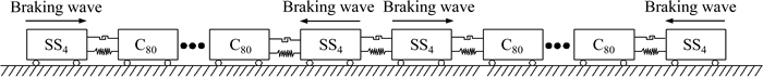
Fig. 2 1+2+1 marshalling train

Fig. 3 Velocity method simulation of coupler
Based on the New-mark method, the relationship between acceleration, velocity and displacement can be expressed as follows:
 (6)
(6)
 (7)
(7)
where xt and xt+��t refer to the displacement at time t and at time t+��t, respectively; vt and vt+��t refer to the velocity at time t and at time t+��t, respectively; at+��t represents the acceleration at time t+��t. If xt and vt are determined, at+��t can be calculated, and xt+��t , vt+��t can also be determined. So, if the initial state is given, according to this regulation, the parameters at every time interval will be solved. The flow diagram is shown in Fig. 4.
3 Emergency braking analysis
3.1 Model validation
The simulation results of the validation model are compared with the test data in Ref. [10]. The marshalling form is SS3��1+C63��122. The brake shoe pressure and the air braking force are calculated according to Ref. [23]. The working condition for the model validated is the emergency braking of the train on a flat track at the initial speed of 63.7 km/h. The comparison of the results between the experiment and the simulation are shown in Fig. 5.
According to Fig. 5, in the two curves, both the peak values appear at the latter half of the train, which is at about 2/3 of the length of the train. And the maximum compressive forces are approximately the same, about 1050 kN. For the vehicles away from the peak values, the coupler forces decrease. The smallest coupler compression forces are at the head and at the end of the train.

Fig. 4 Flow diagram of numerical calculation
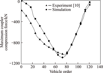
Fig. 5 Validation of numerical model
It can be seen that there are small differences between the two results. Differences exist at the first half of the two curves, and gaps become small at the latter half, which are mainly, caused by the initial state of the couplers and the driver's manipulation. In the experiment, the initial pressure was in the couplers. When the train began to brake, there were tensions or compressions in different couplers. So in the experiment, at the beginning of the braking, vehicles at different locations were subject to forces with different sizes. The driver��s manipulation also influenced the experiment result because the braking force first appeared at the locomotive, which was affected by the drivers�� driving style. While in the simulation, according to Section 2.4, the coupler model was simplified and there was no initial pressure in the couplers. At the same time, the working condition was an ideal state. All couplers were in a free state. And the initial coupler forces wouldn��t be influenced by other factors.
As shown in Fig. 5, the change regulations of the curves for simulation and experiment are generally the same. The location and the size of the maximum compressive force in the simulation is similar to that in the experiment. Hence, the simulation results can be considered to be consistent with the experimental result. So, the model introduced in this study and the numerical integral method used in the solution process are credible.
3.2 Simulation results
In this work, the braking process of the 1+2+1 marshalling train was simulated. For the 1+2+1 marshalling train, the locomotives and wagons are SS4 and C80. Compared with SS3 and C63, SS4 and C80 have some differences. They have different mass, different brake valves, different draft gear and different braking wave velocity. But the model built in Section 2 is suitable for the two trains. The calculation equations and the numerical integral methods for the two trains are the same, which has been proved to be correct in Section 3.1. So, the simulation results for the 1+2+1 marshalling train in this study are credible.
The working condition is the emergency braking of the train on a flat track at the initial speed of 80 km/h with all locomotives functioning simultaneously. The distributions of the coupler maximum compressive forces and strokes along the train are shown in Fig. 6.
From Fig. 6(a), it can be seen that four peak values appear in the distribution of the coupler maximum compressive forces. And the four peak values are nearly the same, about 700 kN, which is the maximum value of the compressive forces during the braking. The minimum value appears at the middle of two locomotives. Because the braking waves from two locomotives reach the middle at the same time, the forces exerted on the vehicle at the middle are balanced out. So, the coupler force at the middle is the smallest.
Figure 6(b) shows the distribution of the coupler maximum compressive strokes along the train. It indicates that the maximum compressive stroke is less than 25 mm, which is within the acceptable compressive stroke range.

Fig. 6 Numerical results of emergency braking process:
4 Analysis of main factors affecting coupler longitudinal force
4.1 Initial braking velocity
When the heavy haul train is running, it will be braked at an initial speed. Different initial braking speeds have an influence on the longitudinal forces of the couplers. In this study, the distributions of the maximum compressive forces and strokes are analyzed when the 1+2+1 marshalling train is emergency braking with different initial velocities. The simulation results are shown in Fig. 7.
The simulation results show that with the initial braking velocity increasing, the maximum coupler forces and strokes decrease. The maximum compressive force is 670 kN at the initial velocity of 100 km/h. While when the initial velocity reduces to 40 km/h, the maximum compressive force reaches 780 kN. It shows that a low initial braking velocity will lead to a high compressive force. The reason is that the air braking force decreases with the initial braking velocity increasing [1, 23]. The resistance force has little change. According to Eq. (2), the differences of the accelerations of two adjacent vehicles reduce. So, the longitudinal vibration is weakened, leading to the reduction of coupler compressive forces.

Fig. 7 Numerical results with different initial braking velocity:
The conclusion can be drawn that when the train is emergency braking at a lower speed, the coupler compressive forces and strokes are higher. It approves that the emergency braking at a lower speed will increase the longitudinal impact. Therefore, during the process of the heavy haul train operation, emergency braking at a low speed should be avoided.
4.2 Locomotives synchronization time
For the 1+2+1 marshalling train, the locomotives are distributed at different locations. The braking waves generated by different locomotives spread from different locations. When the heavy haul train is emergency braking, the slave locomotives may brake leading or lagging of the master locomotive��s action. The response time of slave locomotives will influence the coupler longitudinal forces and strokes. Figure 8 shows how the synchronization time influences the distributions of the maximum compressive forces and maximum compressive strokes.

Fig. 8 Numerical results with different locomotives synchronization time:
As shown in Fig. 8, if the response time of slave locomotives is longer, the coupler compressive forces and strokes are higher. When all locomotives brake simultaneously, the coupler compressive forces and strokes will be reduced to the lowest level. When all the locomotives don��t brake simultaneously, the vehicles begin to brake at different times, leading to longitudinal impact along the train. The increase of the response time of slave locomotives will strengthen the longitudinal impact, which causes the higher longitudinal force and stroke.
Therefore, keeping synchronism between the master locomotive and slave locomotives helps to lower the coupler compressive forces and strokes, which contributes to improving the running safety of the heavy haul train.
4.3 Coupler stiffness
The coupler design parameters of the heavy haul train are introduced in Ref. [26]. As shown in Fig. 9, the main parameters consist of the maximum stokes xmax, the maximum forces Fmax, the coupler stiffness K and the maximum capability Q.
To study how coupler stiffness affects longitudinal force, the coupler capability Q keeps a constant in this study. When the capability Q is a constant, the coupler stiffnesses K1, K2 can be different values, and K1, K2 increase or decrease simultaneously. In this study, the braking process of the heavy haul train with three different stiffness couplers was studied. The values of three different stiffnesses are given in Table 1.

Fig. 9 Simplified diagram of coupler characteristics
Table 1 Three different stiffness values

The simulation working condition is the emergency braking of the 1+2+1 marshalling train on a flat track at the initial speed of 80 km/h with all locomotives functioning simultaneously. The simulation results are shown in Fig. 10.
The simulation results show that with the increase of the coupler stiffness, the coupler compressive forces increase and the compressive strokes reduce. So, properly reducing the coupler stiffness helps to reduce the compressive force. But the reducing coupler stiffness is limited by the compressive strokes. If the compressive strokes exceed the allowed level of stoke, the coupler would be broken, which should be prohibited during the train operation.
To analyze the vehicles longitudinal vibration process, the vehicles longitudinal vibration is simplified as a simple harmonic motion. For the vehicles longitudinal vibration, the vibration frequency, the angular velocity and the acceleration satisfy the equations below:
 (8)
(8)

Fig. 10 Numerical results with different coupler stiffness:
 (9)
(9)
 (10)
(10)
where f, K, M, ��, a and x refer to the vibration frequency, coupler stiffness, the vibrator mass, angular velocity and stroke, respectively. According to the equations above, Eqs. (11) and (12) can be acquired.
 (11)
(11)
 (12)
(12)
In Eq. (12), m refers to the mass of the vehicle, which is a constant; F represents the resultant force the vehicle subjected to, which consists of braking force, resistance and coupler force. In braking state, all the three forces have the same direction. So, the coupler force is positive in correlation with the coupler stiffness. The maximum compressive force changes along with different coupler stiffness.
4.4 Vibrator mass
According to Eq. (8), two measures can be taken to reduce the vibration frequency. One is to reduce coupler stiffness K, and another is to increase vibrator mass M. The mass of a vehicle m is a constant. But the vibrator mass M can be variable. A new method, adding rigid arm connections, is added on purpose in this article to increase the vibrator mass. In the train multi body dynamics model mentioned above, all vehicles are connected by the coupler drafts. In the new model, partial coupler drafts are replaced with the rigid arm connections. Every two vehicles are connected by rigid arms, as shown in Fig. 11.
The coupler device is not included in the rigid arm structure. The two vehicles connected by rigid arms have the same displacement, velocity and acceleration. So, the two vehicles can be regarded as a new vibrator, the quality of which is twice the original vehicle in Section 3.2. And the number of the vibrators is half of the original ones.
The emergency braking process of the 1+2+1 combined train with rigid arm connection was simulated. The working condition of the new model is also the emergency braking of the train on a flat track at the initial speed of 80 km/h with all locomotives functioning simultaneously. Conditions of the train with and without rigid arm connections were simulated and compared. Figure 12 shows the comparison of the coupler compressive forces and stokes under the two conditions.
The simulation results show that in the emergency braking process, the maximum compressive forces and compressive strokes of the train with rigid arm connection are much smaller than those of the train without rigid arm connection. This can also be explained by Eq. (12). The coupler force is negative in correlation with the vibration mass. So, the coupler force can be changed by using different vibration mass. Adding rigid arm connection is one of the methods changing the vibrator mass. It means that adding rigid arm connection is also a method to reduce the compressive forces and strokes, which is beneficial to improve the running safety of the heavy haul train.
5 Conclusions
1) With the reduction of the initial braking velocity, the maximum coupler compressive forces and strokes increase. When the train is emergency braking at a low speed, the compressive forces and strokes are much higher, which can cause damage of the coupler. Therefore, emergency braking at a low speed should be avoided.
2) The response time of the slave locomotives should be cut down. Keeping synchronism between master and slave locomotives effectively helps to reduce longitudinal compressive forces and strokes.
3) When the coupler stiffness is reduced, the coupler compressive forces reduce but the compressive strokes increase. So, properly reducing the coupler stiffness helps to reduce the compressive force. And the reducing coupler stiffness is limited by the compressive strokes.
4) By adding rigid arm connections, every two vehicles are regarded as a new vibrator and the vibrator mass increases, which helps to bring down the longitudinal vibration frequency. Consequently, the longitudinal compressive forces and strokes will be lowered.

Fig. 11 New train longitudinal dynamics model with rigid arm connection
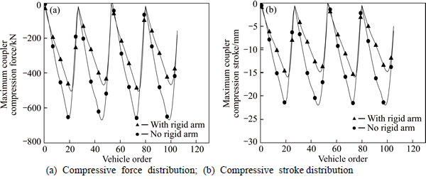
Fig. 12 Numerical results with or without rigid arm connection:
References
[1] GENG Zhi-xiu. Heavy-haul transportation technologies on Datong- Qinhuangdao railway [M]. Beijing: China Railway Publishing House, 2009. (in Chinese)
[2] XIA Xiao-hua, ZHANG Jiang-feng. Modeling and control of heavy-haul trains [J]. IEEE control systems, 2011, 31(4): 18�C31.
[3] CHOU M, XIA X, KAYSER C. Modeling and model validation of heavy haul trains equipped with electronically controlled pneumatic brake systems [J]. Control Engineering Practice, 2007, 15(4): 501�C509.
[4] PUGI L, FIORAVANTI D, RINDI A. Modelling the longitudinal dynamics of long freight trains during the braking phase [C]// 12th IFToMM World Congress. Besancon, France, 2007: 1�C6.
[5] SUN Shu-lei. Research on heavy haul train longitudinal impulse dynamics [D]. Chengdu: Southwest Jiaotong University, 2014. (in Chinese)
[6] BRAUT G S, SOLBERG  ,
,  O. Organizational effects of experience from accidents. Learning in the aftermath of the Tretten and
  train accidents [J]. Transportation Research Part A, 2014, 69: 354�C366.
[7] LI Wei. Opinion of coupler break accident in long and big heavy haul train [J]. Railway Locomotive & Car, 2005, 25(2): 50�C51. (in Chinese)
[8] SURYOPUTRO M R, SARI A D, KURNIA R D. Preliminary study for modeling train accident in Indonesia using Swiss Cheese Model [C]// 6th International Conference on Applied Human Factors and Ergonomics (AHFE2015) and the Affiliated Conferences. Las Vegas, America, 2015: 3100�C3106.
[9] WANG Yue-ming, TAO Qiang, LU Yang, NI Chun-shuang, LI Xue-feng. Test research of 20000t heavy haul train on Da-Qin railway [C]// New Progress in Science and Technology-Proceedings of the 55th Anniversary of Academy of Railway Sciences. Beijing: China Academic Journal Electronic Publishing House, 2005: 135�C141. (in Chinese)
[10] FAN Pei-xin. Longitudinal force of heavy haul train during traction, speed regulation and emergency brake-the testing research of 10000 t heavy haul train on Da-Qin railway [J]. Journal of Southwest Jiaotong University, 1994, 29(1): 57�C64. (in Chinese)
[11] ZOBORY I,  E. On real-time simulation of the longitudinal dynamics of trains on specified railway line [J]. Periodica Polytechnica Ser Transp Eng, 1995, 23(1): 3�C18.
[12] RAO J S, RAGHAVACHARYULU E. Mathematical modeling to simulate the transient dynamic longitudinal forces in draw bars of a train-consist [J]. Journal of Sound and Vibration, 1984, 94(3): 365�C379.
[13] CANTONE L, KARBSTEIN R,  L, NEGRETTI D, TIONE R,
  H J. Train dynamic simulation-a new approach [C]// World Congress on Railway Research. Seoul, Korea, 2008.
[14] GAO Kai, HUANG Zhi-wu, WANG Jing, PENG Jun, LIU Wei-rong. Decentralized control of heavy haul trains with input constraints and communication delays [J]. Control Engineering Practice, 2013, 21(4): 420�C427.
[15] WEI Hong-liang, YU Yue-bin, LEI En-qiang, LI Xiang-wei. Key technology and research topics of heavy haul and fast wagon [J]. Lecture Notes in Electrical Engineering, 2012, 147: 335�C343.
[16] ZHANG Zhi-chao, LI Gu, CHU Gao-feng. Summary and development of the longitudinal dynamic calculation program for heavy haul trains [J]. Railway Locomotive & Car, 2014, 34(6): 1�C7. (in Chinese)
[17]  M. Simulation study of longitudinal forces in the coupling device of heavy freight trains [J]. Advances in Science and Technology Research Journal, 2014, 8(21): 24�C30.
[18] WEI Wei, AHMADIAN M, ZHANG Jun. Heavy haul train simulation of air brake system and longitudinal dynamics [C]// Proceedings of the 2014 Joint Rail Conference. Colorado, USA, 2014: 1�C8.
[19] MA Wei-hua, LUO Shi-hui, SONG Rong-rong. A study of the dynamic performance of the heavy haul locomotive with the longitudinal press force on coupler [C]// International Conference on Transportation Engineering. Chengdu, 2009: 2496�C2501.
[20] CRACIUN C, MITU A M, CRUCEANU C, SIRETEANU T. Modeling the buffers hysteretic behavior for evaluation of longitudinal dynamic in-train forces [C]// SISOM 2012 and Session of the Commission of Acoustics. Bucharest, Romania, 2012: 105�C111.
[21] TANG Hua-ping, TANG Yun-jun, TAO Gong-an. Active vibration control of multibody system with quick startup and brake based on active damping [J]. Journal of Central South University of Technology, 2006, 13(4): 417�C421.
[22] YANG Liang-liang, LUO Shi-hui, FU Mao-hai, ZHOU Shang-shu. Study on effect of longitudinal impulse for 20000t heavy haul combined train [J]. Electric Drive for Locomotives, 2014(3): 34�C39. (in Chinese)
[23] TB/T 1407�C1998. Regulations on railway train traction calculation [S]. (in Chinese)
[24] HUANG Yun-hua, LI Fei, FU Mao-hai, BU Ji-ling. Comparison of algorithms for discontinuity on the characteristics curves of draft gears [J]. Journal of Southwest Jiaotong University, 2005, 40(1): 9�C12. (in Chinese)
[25] ZHANG Xiong, WANG Tian-shu. Computational dynamics [M]. Beijing: Tsinghua University Press, 2007. (in Chinese)
[26] WANG Xiao-long, YU Lian-you, WANG Feng-zhou, WANG Jun-long, HAO Wei. Study on design parameters of the coupler of heavy haul train in China [J]. Railway Vehicle, 2010, 48(3): 8�C12. (in Chinese)
(Edited by YANG Hua)
Cite this article as: GAO Guang-jun, CHEN Wei, ZHANG Jie, DONG Hai-peng, ZOU Xiang, LI Jian, GUAN Wei-yuan. Analysis of longitudinal forces of coupler devices in emergency braking process for heavy haul trains [J]. Journal of Central South University, 2017, 24(10): 2449�C2457. DOI:https://doi.org/10.1007/s11771-017-3656-9.
Foundation item: Project(U1334208) supported by the National Natural Science Foundation of China; Project(2016zzts331) supported by the Fundamental Research Funds for the Central Universities, China
Received date: 2016-01-29; Accepted date: 2016-05-09
Corresponding author: GAO Guang-jun, Professor, PhD; Tel: +86�C731�C82655294; E mail: gjgao@csu.edu.cn

