J. Cent. South Univ. Technol. (2007)03-0370-04
DOI: 10.1007/s11771-007-0073-5

Effect of technological parameters on optical performance of fiber coupler
SHUAI Ci-jun(帅词俊), DUAN Ji-an(段吉安), ZHONG Jue(钟 掘)
(School of Mechanical and Electrical Engineering, Central South University, Changsha 410083, China)
Abstract: To find out the influence of technological parameters on optical performance of fused optical fiber device, the fiber coupler was served as subject investigated by using the fused biconical taper machining as experimental setup. Fused fiber coupler’s optical performances such as insertion loss, excess loss, directivity and uniformity were tested with the optical test system that was constituted of tunable laser and optical spectrum analyzer. Especially the relationship between optical performance and drawing speed was investigated. The experimental results show that the optical performance is closely related to process conditions. At fused temperature of 1 200 ℃, there exists a drawing speed of 150 μm/s, which makes the device’s performance optimum. Out of this speed region, the optical performance drops quickly. At drawing speed of 200 μm/s, the excess loss is relatively small when the fused temperature is above 1 200 ℃. So the technological parameters have close relationship with optical performance of the coupler, and the good performance coupler can’t get until the drawing speed and fused temperature match accurately.
Key words: optical fiber coupler; fused biconical taper; technological parameter; optical performance
1 Introduction
Optical fiber coupler is the most representative in all fiber devices and also a basic device making up of other devices[1-4]. It is widely used in optical fiber communication. At present, its types are diverse on the market. The fused fiber coupler is the most widely used couple among those couplers. Such coupler is extensively used because its optical performance is very good such as simpler manufacturing equipment and lower cost[5-10].
However the research on the technological parameters is poor and not sufficient. The fused biconical technology(FBT) is still an empirical method. The performance of the devices is unsatisfactory, and has many defaults such as poor conformance of optical performance, low efficiency and low rate of finished products. In this study, a six-axis fibre coupler machine was taken as experimental setup, the relationship between technological parameters and optical performance of fibre coupler was analyzed.
2 Experimental
2.1 Materials and instruments
The SMF28 fiber fabricated by Corning Corporation was used. The refractive index of its core was 1.460, and the diameter was 8.5 μm. Refractive index of envelope was 1.456, and its diameter was 125 μm. Diameter of cladding was 250 μm. The experimental system was constituted of a six-axis (XYGD-SA2002) optical fiber coupler machine, a K series thermocouple, a UJ-33 type potentiometer, a tunable laser of Agilent 86142B and an optical spectrum analyzer of Agilent 86142B.
2.2 Manufacturing process
Fused fiber coupler was fabricated with the fused biconical taper technology on an optical fiber coupler machine. Its fabrication process is as follows[11-14]: two parallel fibers were positioned very close to each other, heated by burning the combustible gas, drawn at a certain speed by micro-machine, and then a biconical taper was formed. Finally the cross-section diameter of fused region was decreased from 125 ?m to about 20 ?m. In the experiment, fused flame was gained by burning high pure C3H8 and O2, and the temperature of the flame was about 1 200℃ measured with K series thermocouple and UJ-33-type potentiometer. Fig.1 shows the sketch map of fiber coupler machine.
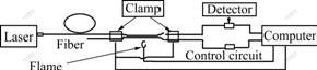
Fig.1 Sketch map of fiber coupler machine
Before fabricating optical fiber coupler, the fiber needs pre-treatment, such as peeling and cleaning. During the fabrication process of coupler, the optical detector converted the optical power to electrical signals. Then the electrical signals were converted to digit signals by A/D and transmitted to the computer system in the end. The computer system dealt with them and counted the parameters of their corresponding coupling ratios, insert loss, additional loss, etc, and displayed them in real time. When the coupling ratio reached the set value in advance, the computer would send out stopping signal, then the main tapering platform stopped drawing and heating. At last, the coupler was encapsulated. The process flow is shown in Fig.2. The samples fabricated under different technological conditions are acquired by changing the drawing speed and fused temperature. Here the preset coupling ratio was 44.
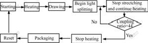
Fig.2 Process flow of fabricated fiber coupler
2.3 Optical performance testing
Main performance indexes of fiber coupler are insertion loss, excess loss, directivity, uniformity and so on. The performance testing system was made up of the tunable laser of Agilent 86142B and the optical spectrum analyzer of Agilent 86142B, as shown in Fig.3. Every point in the experimental curve was an average value of 20 experimental data.

Fig.3 Testing system of optical performance
3 Effect of technology on performance
3.1 Drawing speed and optical performance
3.1.1 Insertion loss
Insertion loss is the ratio of optical power of some outputting port to all input optical power. Its expression is
 (1)
(1)
where Lil is the insertion loss, POUT,i is the optical power of output port i, and PIN is the input optical power.
By using the testing system, the value of insertion loss is determined as 3.009 dB when the drawing speed is 150 μm/s. This meets the requirement of typical performance index of coupler’s insertion loss. When the other technological conditions are not changed, the couplers insertion loss at different drawing speeds is gained, as shown in Fig.4 (Every point in the figure is the average of 20 test values).
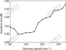
Fig.4 Relation between drawing speed and insertion loss
3.1.2 Excess loss
Excess loss is the ratio of all the outputting light power to all the input light power. Its expression is
 (2)
(2)
where Lel is the excess loss, POUT is the output optical power, and PIN is the input optical power, i is the number of output ports.
For optical coupler, excess loss is the most important performance index. It reflects the inherent loss in the coupler’s fabrication progress. While insertion loss expresses the power conditions of each outputting port, which not only includes factors of loss, but also the influence of optical ratio.
Excess loss is 0.069 dB by testing when the drawing speed is 150 μm/s, less than the requirement of 0.1 dB, which complies with the performance index. When the other technological conditions are not changed, the coupler’s excess losses are gained at different drawing speeds, as shown in Fig.5. It is found from Fig.5 that there is a very narrow speed region (Here is 150 μm/s), which makes excess loss of fiber coupler lower, that is, the performance is good. Performance of the coupler falls rapidly when drawing speed is out of this region.
3.1.3 Directivity
Directivity is a special technological term of optical fiber coupler, which is a parameter of directional translation characteristics. Taking optical fiber coupler of X type by fused biconical taper as an example, directivity is defined as the ratio of the power of input 2 to the power of total inputs. Its expression is
 (3)
(3)
where Ldl is directivity, PIN1 is the optical power of input port, and PIN2 is the optical power of output port.
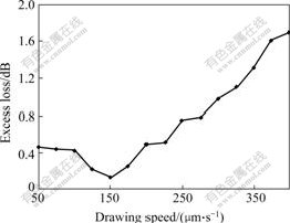
Fig.5 Relationship between drawing speed and excess loss
Directivity is 66.375 dB by testing when the drawing speed is 150 μm/s, more than 60 dB, which complies with typical performance index. When the other technical conditions are not changed, the coupler’s directivities are gained at different drawing speeds, as shown in Fig.6.
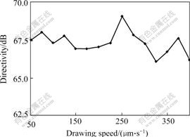
Fig.6 Relationship between drawing speed and directivity
3.1.4 Uniformity
Uniformity is a parameter identified uneven degree of a device. It is the most variation value of input power in each output port, when coupler is in the field of working bandwidth. Its expression is
 (4)
(4)
Uniformity of fiber coupler is 0.408 dB at the drawing speed of 150 μm/s, which shows that the uniformity of output port is good. When other technological conditions are not changed, the coupler’s uniformity is gained at different drawing speeds, as shown in Fig.7.
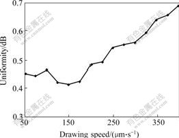
Fig.7 Relationship between drawing speed and uniformity
3.2 Fused temperature and optical performance
When drawing speed is 200 μm/s, the relationship between excess loss and fused temperature is shown in Fig.8. It is discovered that the fused temperature has great effect on the excess loss. When the drawing speed is 200 μm/s, the excess loss of the fiber coupler is the lowest at the fused temperature of 1 300-1 400 ℃.
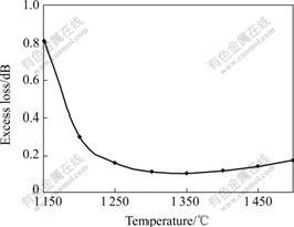
Fig.8 Relationship between fused temperature and excess loss
4 Conclusions
1) The technological parameters have great effect on the performance of fiber couple. There is an optimal drawing speed at a given fused temperature. The performance of device is good when the drawing speed is in this region. When the drawing speed is 200 μm/s, the excess loss of the fiber coupler is the lowest at the fused temperature of 1 300-1400 ℃.
2) The good performance coupler can’t get until the drawing speed and fused temperature match accurately. Those researches supply reference to manufacturing technological improvement and optimization of fiber coupler.
References
[1] YANG Wei. Technological advance and trend of optical passive devices[J]. Broad Band in the World, 2003(3): 38-40. (in Chinese)
[2] SONG Jin-sheng. Technological advance and developmental trend of passive devices in China[J]. Broad Band Web in the World, 2002, 9(11): 103-105. (in Chinese)
[3] LI Ling, HUANG Yong-qing. Corresponding Foundation of Optical Fiber[M]. Beijing: National Defence and Industry Press, 1999. (in Chinese)
[4] GHATAK A K, THYAGARAJAN K. Introduction to Fiber Optics[M]. New York: Cambridge University Press, 1999.
[5] SHAI Ci-jun, DUAN Ji-an. Relationship between rheological manufacturing process and optical performance of fiber coupler[J]. J Cent South Univ Technol, 2006, 13(2): 175-180.
[6] FENG Da, LI Zheng, TANG Dan. Model of 2×2 fused single-mode-fiber couplers[J]. Acta Photonica Sinica, 2003, 32(11): 1316-1320.
[7] NAGATA H. Chemical properties of fused fiber coupler[J]. Surface Optical Fiber Technology, 2000, 6(3): 324-328.
[8] HSIEH C S, WU T L, CHENG W H. Optimum approach for fabrication of low loss fused fiber couplers[J]. Materials Chemistry and Physics, 2001, 69(1): 199-203.
[9] PAL B P, CHAUDHURI P R, SHENOY M R. Fabrication and modeling of fused biconical tapered fiber couplers[J]. Fiber and Integrated Optics, 2003, 22(2): 97-117.
[10] SHUAI Ci-jun, DUAN Ji-an, ZHONG Jue. Technical sensitiveness in the rheological manufacture progress of fused taper coupler[J]. Optics and Precision Engineering, 2005,13(1): 40-46. (in Chinese)
[11] YANG Jia, ZHANG Tan-hao, YANG Hui-zhan. Research on return wave interference of X-type optical fiber coupler[J]. Journal of Optoelectronic・Laser, 2003, 14(9): 933-935. (in Chinese)
[12] HAKEN U, HUMBACH O, ORTNER S. Refractive index of silica glass: Influence of fictive temperature[J]. J Non-cryst Solids, 2000, 265: 9-18.
[13] HSU C M, SU C T, LIAO D. A novel approach for optimizing the optical performance of the broadband tap coupler[J]. International Journal of Systems Science, 2003, 34(3): 215-226.
[14] ROYCHAUDHURI P, SHENOY M R, PAL B P. Flame-fused optical fiber directional couplers: Fabrication and automated process control[J]. IETE Journal of Research, 1997, 43(6): 433-438.
(Edited by LI Xiang-qun)
Foundation item: Project (50605063) supported by the National Natural Science Foundation of China; Project(NCET-040753) supported by New Century Excellent Talents in University of China; Project (20050533037) supported by the Doctoral Program of Higher Education of China
Received date: 2006-08-24; Accepted date: 2006-09-29
Corresponding author: DUAN Ji-an, PhD; Tel: +86-731-8836858; E-mail:duanjian@mail.csu.edu.cn

