J. Cent. South Univ. (2012) 19: 2008-2015
DOI: 10.1007/s11771-012-1238-4
Upper bound solutions of stability factor of shallow tunnels in saturated soil based on strength reduction technique
HUANG Fu(�Ƹ�)1,2, ZHANG Dao-bing(�ŵ���)2, SUN Zhi-bin(��־��)2, JIN Qi-yun(������)2
1. School of Civil Engineering and Architecture,
Changsha University of Science and Technology, Changsha 410004, China;
2. School of Civil Engineering, Central South University, Changsha 410075, China
? Central South University Press and Springer-Verlag Berlin Heidelberg 2012
Abstract: Based on the upper bound theorem of limit analysis, the factor of safety for shallow tunnel in saturated soil is calculated in conjunction with the strength reduction technique. To analyze the influence of the pore pressure on the factor of safety for shallow tunnel, the power of pore pressure is regarded as a power of external force in the energy calculation. Using the rigid multiple-block failure mechanism, the objective function for the factor of safety is constructed and the optimal solutions are derived by employing the sequential quadratic programming. According to the results of optimization calculation, the factor of safety of shallow tunnel for different pore pressure coefficients and variational groundwater tables are obtained. The parameter analysis shows that the pore pressure coefficient and the location of the groundwater table have significant influence on the factor of safety for shallow tunnel.
Key words: strength reduction technique; upper bound theorem; pore pressure; shallow tunnel; factor of safety
1 Introduction
The strength reduction method was first proposed by BISHOP [1] in 1955. The core of this method is the factor of safety which is defined as the ratio of the available shear strength of the soil to what is required to maintain equilibrium. According to the definition and the calculating procedure, the factor of safety is also known as reduction coefficient. There are several advantages for the application of the strength reduction method in geotechnical stability analysis. Firstly, the computational process of this method is simple and the mechanical meaning is clear. Furthermore, the factor of safety that satisfies engineering requirement can be calculated by combining this method with the traditional methods such as finite element, finite deference, limit equilibrium and limit analysis methods. To analyze the stability of slope induced by the fluctuation of water level or rainfall, HUANG and JIA [2] developed a finite element method with strength reduction technique to calculate the safety factors of slope including the effects of unsaturated transient seepage. Using the finite element�Cstrength reduction technique, ZHENG et al [3] searched the critical slip surfaces of slope and the validity of this method was proved by comparing it with the results calculated by other scholars. Moreover, by combining finite difference code and strength reduction technique, DAWSON et al [4] computed the stability numbers of homogenous slope, and the similarity between their results and the upper bound solutions of CHEN [5] demonstrated that the log-spiral failure mechanism is effective.
According to the calculating procedure of finite element method, it can be found that the key factor in applying this method in geotechnical stability analysis successfully is how to define the failure of the soil. However, there is not a generally accepted criterion of failure for soil in geotechnical engineering at present. Consequently, some scholars proposed several possible criteria of failure on the basis of their own research results. Bulging or progressive loss of ground along the vertical cut was regarded as failure of vertical slope by SNITBHAN and CHEN [6]. GRIFFITHS and LANE [7] thought when a slope arrives at the critical state, the iteration numbers would exceed the user-specified maximum value and the ��failure�� would occur. Based on the stress field, KIM and LEE [8] used a critical slip surface which is associated with the minimum factor of safety to define the failure of slope. Since the calculating results depend on which criterion is selected, the difference of ultimate loads or minimum factor of safety for a project example would be significant when different criteria are employed. Therefore, the application of the finite element�Cstrength reduction technique in geotechnical engineering has been restricted.
Limit analysis is a classical method which is widely used in slope stability problems [9-13], active and passive earth pressure problems [14-16], anchors in sand [17], ultimate bearing capacity of foundations [18-21], and shallow tunnel stability problems [22-24]. Combined with upper bound theorem of limit analysis, the relationship between the external rate of work and the internal energy rate of dissipation can be used to control the convergence of iteration in the strength reduction technique, and the selection of failure criterion which occurs in the finite element�Cstrength reduction technique can be avoided. As no subjective selection with respect to failure criterion is required, the limit analysis�Cstrength reduction technique contributes to obtain more precise results. In the practical projects, engineers wish to establish an estimate system to evaluate the stability of tunnel when the supporting pressure of tunnel is known. Based on limit analysis-strength reduction technique, the factor of safety for shallow tunnel is computed in this work. Moreover, the effects of pore water pressure coefficient and the location of underground water table on the factor of safety for shallow tunnel are analyzed. According to the values of factor of safety for different conditions, the stability of shallow tunnel is estimated quantificationally.
2 Failure mechanism of shallow tunnel in frictional and cohesive material
Since the energy calculation of upper bound theorem is based on failure mechanism, a failure mechanism which describes the failure characteristic of shallow tunnel is the key factor to obtain a precise upper bound solution. Based on the centrifugal model test result of Cambridge University, DAVIS et al [22] proposed four effective failure mechanisms for shallow tunnel. As the frictional property of soil was not included in their failure mechanisms, the four mechanisms can only be applied to cohesive materials. To calculate the upper bound solution of supporting pressure for shallow tunnel in frictional and cohesive materials, YANG and YANG [24] constructed a rigid multiple-block failure mechanism, as illustrated in Fig. 1. Since the rigid multiple-block failure mechanism represents the failure characteristic and compatibility relationship of velocity vector for shallow tunnel in frictional and cohesive materials, precise upper bound solutions can be provided by this mechanism. Due to these advantages, the rigid multiple-block failure mechanism is also employed to derive the upper bound solutions of factor of safety for shallow tunnel in this work.

Fig. 1 Failure mechanism of shallow tunnel and velocity vector relationship proposed by YANG and YANG [24]: (a) Failure mechanism; (b) Velocity vector relationship
3 Factor of safety for tunnel by limit analysis-strength reduction technique
According to the definition of strength reduction technique and upper bound theorem, the factor of safety for shallow tunnel can be derived and the calculating procedure is as follows. Firstly, the initial cohesion c and friction angle �� of soil are divided by reduction factor Fs to calculate the reduced strength parameters cf and ��f. Then, the reduced strength parameters are used to derive the dissipation power and external loads power in the kinematically admissible velocity field. Based on the upper bound theorem, the objective function of factor of safety which includes a quantity of angle variables is obtained. Furthermore, a sequential quadratic programming is employed to optimize the objective function. Finally, by applying the geometrical relationship and velocity vector relationship of the velocity field to controlling the convergence of iteration, the reduction factor in limit state is obtained. According to the calculating procedure mentioned above, the strength parameters which have been reduced to cf and ��f are
 (1)
(1)
where Fs is reduction factor, namely factor of safety.
Since the external load power and the dissipation power have been given by YANG and YANG [24], the concrete formula of these powers are not presented in this work. Using the failure mechanism illustrated in Fig. 1 and the formulas derived by YANG and YANG [24], the critical supporting pressure qcr can be computed:
 (2)
(2)
where P�� is the power of the soil weight, PV is the power of dissipation, Ps is the power of the pressure acting on the ground, b is the half width of the tunnel, ��4 is the angle variable in the velocity field, and v0 and v4 are the velocities of the rigid blocks.
Substituting the reduced strength parameters cf and ��f into Eq. (2) and assuming that the actual supporting pressure is equal to the critical supporting pressure qcr, the objective function of factor of safety f(��1,����n, ��1,����n) is obtained. However, the objective function is just an expression of numerous upper bound solutions. Therefore, the calculation of the optimal bound solution of factor of safety can be regarded as searching the minimum value of objective function f(��1,����n, ��1,����n). As the objective function includes plenty of angle variables and trigonometric function, a sequential quadratic programming is employed to optimize the objective function. Moreover, as the compatibility relation of velocity in the velocity field requires to be satisfied in the optimization procedure, the search for upper bound solution turns to the search for the minimum value of objective function when corresponding constraint condition is satisfied. The expression of mathematical planning for the problem is
min Fs=Fs (��1,����n, ��1,����n, Fs) (3)
 (4)
(4)
where Eq. (3) is the main programming of the optimization calculation, Eq. (4) is the constraint equation derived from the compatibility relation of rigid-block velocity vector, and ��1,����n, ��1,����n are the angle variables illustrated in Fig. 1.
Furthermore, the upper bound theorem can be applied to the geotechnical material if the material is subjected to some ideal properties: 1) The material is perfectly plastic material with no regard to the strain hardening and strain softening feature; 2) The geometric deformation of failure mechanism induced by limit load is insignificant.
4 Comparison with existing methods
To evaluate the stability of shallow tunnel, BROMS and BENNERMARK [25] defined a stability ratio on the basis of experimental results and field observed data, which can be expressed as
 (5)
(5)
where ��s is the uniform pressure acting on the ground surface, ��T is the supporting pressure acting on the tunnel face, �� is the unit weight, C is the tunnel depth, D is the tunnel diameter and cu is undrained shear strength. It can be seen from Eq. (5) that the stability ratio is determined by supporting pressure ��T when other parameters are given. Therefore, substituting the supporting pressure which is calculated by the upper bound theorem into Eq. (5), some scholars [22, 26] derived the upper bound solution of stability ratio for shallow tunnel. The research results of DAWSON et al [4] showed that, when the actual height of slope is equal to the critical height calculated by the upper bound theorem, the factor of safety for slope is exactly 1.0. Extending this theory to tunnel stability analysis, we can conclude that when the actual supporting pressure is equal to the critical supporting pressure, the factor of safety of tunnel computed by strength reduction technique is also 1.0. It is obvious that, substituting the first formula of Eq. (1) into Eq. (5), the stability ratio of shallow tunnel can be calculated when factor of safety of tunnel has been obtained.
To evaluate the validity of the method used in this work, employing the same example, the results derived from limit analysis-strength reduction technique are compared with the solutions calculated by DAVIS et al [22] and YANG and HUANG [26]. The results of comparison are illustrated in Table 1. In addition, the solutions of DAVIS et al [22] are calculated by upper bound theorem while the results of YANG and HUANG [26] are based on finite difference method. As can be seen in Table 1, the factors of safety calculated with the method in this work are closer to 1.0 and more precise than the solutions of YANG and HUANG [26]. Besides, the stability ratios computed in this work are almost equal to those calculated by DAVIS et al [22]. Therefore, the good agreement of the results between them proves that the method used in this work is valid.
Table 1 Comparison of stability ratio and factor of safety

5 Upper bound limit analysis of shallow tunnel with pore water pressure
5.1 Failure mechanism of shallow tunnel with pore water pressure
The definition of pore pressure coefficient was first proposed by SKEMPTON [27]. According to this definition, BISHOP [28] developed the calculating method of pore water pressure by regarding the pore water pressure as a fraction of the overburden stress:
 (6)
(6)
where ru is the pore pressure coefficient, and z is the vertical distance between any point underground and ground surface. By assuming that the work of water pressure is equal to the sum of pore pressure work on skeleton and the work of the water pressure on boundary, VIRATJANDR and MICHALOWSKI [29] considered the effects of pore pressure in the framework of the upper bound theorem of limit analysis for slope stability, which can be written as
 (7)
(7)
where  is the strain rate in the kinematically admissible velocity field, V is the volume of the mechanism, vi is the velocity along the velocity discontinuity surface, ni is the unit variable along the velocity discontinuity surface and s is the boundary of velocity field. According to the assumption of the upper bound theorem, the strain rate in the failure mechanism is equal to zero, which means that the power of pore water pressure is completely produced by the part of pressure acting on the failure boundary.
As the pore water pressure has no effect on the failure mechanism of shallow tunnel, by extending the mechanism illustrated in Fig. 1 to saturated soil, the mechanism which includes the effect of pore pressure is shown in Fig. 2. According to the theory of VIRATJANDR and MICHALOWSKI [29], the power of pore water pressure along the velocity discontinuity line can be written as
 (8)
(8)
where  -
- are the areas of region composed of the velocity discontinuity line and the vertical lines from the endpoints of the velocity discontinuity line to the ground surface; v0-v4 are the velocities of the rigid blocks. Since the failure mechanism is the same, the power of the supporting pressure PT, the power of the soil weight P�� and the power of dissipation P�� in saturated soil are in accordance with these powers represented in Eq. (2). Therefore, the critical supporting pressure qcr of shallow tunnel by taking into account of the effect of pore pressure is expressed as
 (9)
(9)

Fig. 2 Failure mechanism of shallow tunnel in saturated soil
With regard to the calculating procedure of the factor of safety for shallow tunnel in dry soil, the mathematical planning for the factor of safety which considers the effect of pore pressure is obtained:
min Fs=Fs (��1,����n, ��1,����n, Fs) (10)
 (11)
(11)
5.2 Parameter study of factor of safety of shallow tunnel
To investigate the effect of different parameters on the factors of safety for shallow tunnel, reference can be made in Fig. 3, where the values of Fs are plotted as the function of tunnel depth and pore pressure coefficient, respectively, when ��=15��, b=5 m, c=10 kPa, q=200 kPa, ��=20 kN/m3, and the groundwater table is on the ground surface. It can be seen from Fig. 3 that the factor of safety Fs decreases nonlinearly with the increase of the pore pressure coefficient when tunnel depth is fixed. In other words, the stability of shallow tunnel decreases with the increase of the pore pressure coefficient. Therefore, the value of pore pressure coefficient which reflects the magnitude of the pore pressure is an effective parameter to evaluate the influence of pore pressure on the stability of tunnel.
To analyze the effect of different parameters on the shape of the failure surface of shallow tunnels, the failure surfaces of the shallow tunnel with parameters corresponding to ��=15��, b=5 m, c=10 kPa, q=200 kPa, ��=20 kN/m3 , ru=0-0.4 and h=10 m are illustrated in Fig. 4. It is noted that the potential failure surface expands with the increase of ru when other parameters are fixed. Combined with the changing regularity of the factors of safety, it can be concluded that the stability of tunnel decreases with the increase of ru.
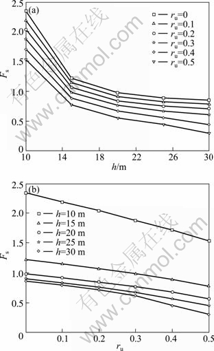
Fig. 3 Factor of safety for shallow tunnel with different tunnel depth (a) and pore pressure coefficient (b) in saturated soil

Fig. 4 Failure surface of shallow tunnel for different pore pressure coefficients in saturated soil
6 Factor of safety for shallow tunnel with variational groundwater table
6.1 Failure mechanism of shallow tunnel for variational groundwater table
The failure mechanism of shallow tunnel for variational groundwater table is illustrated in Fig. 5. It can be seen that there are four types of groundwater table and the vertical distance from each groundwater table to the ground surface is Hn (n=1-4), respectively. To obtain the factor of safety for shallow tunnel with variational groundwater table, some assumptions are given as follows: 1) Only hydrostatic pressure is considered in the calculation, which means that the effect of seepage of groundwater is ignored; 2) The soil under groundwater table is saturated while the soil above groundwater table is completely dry.

Fig. 5 Failure mechanism of shallow tunnel for different groundwater tables
Since the variational groundwater table has no influence on the external load power and dissipation power, these powers for the variational groundwater table are the same as those illustrated in Eq. (2). Different from those whose groundwater table is located on the ground surface, the pore water pressure power for the variational groundwater table can be written as

 (12)
(12)
where  -
-  are the areas of region composed of the velocity discontinuity line and the vertical lines from the endpoints of the velocity discontinuity line to the groundwater table. According to the each power mentioned above, the critical supporting pressure of shallow tunnel for variational groundwater table is obtained:
 (13)
(13)
Based on the sequential quadratic programming, the mathematical planning of the factor of safety for variational groundwater table can be expressed as follows:
min Fs=Fs (��1,����n, ��1,����n, Fs) (14)
 (15)
(15)
6.2 Parameter study for factor of safety of shallow tunnel
In order to analyze the influence of the variational groundwater table on the factors of safety, the values of Fs for the parameters corresponding to ��=15��, b=5 m, c=10 kPa, q=200 kPa, ��=20 kN/m3, h=10 m, ru=0-0.5, and the groundwater table of 0, 2, 4, 6 and 8 m below the ground surface are illustrated in Fig. 6. To describe the change of groundwater table clearly, the groundwater table ratio H/h which is represented by the ratio of Hn to tunnel depth h, is introduced. It can be seen that, the factor of safety Fs increases with the increase of H/h but decreases with the increase of ru value when other parameters are fixed. In other words, the lower the groundwater table, the higher the factor of safety. From the perspective of engineering, this means that reducing the groundwater table is an effective way to improve the stability of shallow tunnel when the tunnel is located in a region where groundwater is abundant.
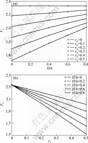
Fig. 6 Factor of safety for shallow tunnel with variational groundwater table and pore pressure coefficient
To study the changing regularity of the shape for the failure surface with variational groundwater tables, the failure surfaces with parameters corresponding to ��=15��, b=5 m, c=10 kPa, q=200 kPa, ��=20 kN/m3, ru=0.5, h= 10 m, and H/h=0, 0.4, 0.8 are illustrated in Fig. 7. It can be seen that, with the rise of the groundwater table, the potential failure surface expands, which causes the decrease of the factor of safety. As a result, the location of groundwater table has significant influence on the factor of safety for shallow tunnel.

Fig. 7 Failure surface of shallow tunnel for variational groundwater table
7 Conclusions
1) Based on the rigid multiple-block failure mechanism, combining upper bound theorem of limit analysis with strength reduction technique, the factor of safety for shallow tunnel is calculated. To evaluate the validity of the method proposed, the stability ratios computed are compared with the existing results in other methods. The comparing results show that the solutions in this work are more precise than those calculated by finite difference method, which proves that the method proposed is valid.
2) To analyze the influence of pore pressure on the stability of shallow tunnel, the effect of pore pressure which is regarded as a power of external force is included in the upper bound theorem. According to this method, the factor of safety and failure surface of shallow tunnel for different pore pressure coefficients and variational groundwater tables are obtained.
3) The parameter analysis shows that the pore pressure coefficient and the location of the groundwater table have significant influence on the factor of safety for shallow tunnel. It is found that the factor of safety decreases with the increase of the pore pressure coefficient and the rise of the groundwater table. Reducing the groundwater table is an effective method to improve the stability of shallow tunnel when the tunnel is excavated in the region where groundwater is abundant.
References
[1] BISHOP A W. The use of the slip circle in the stability analysis of slopes [J]. Geotechnique, 1955, 5(1): 7-17.
[2] HUANG M S, JIA C Q. Strength reduction FEM in stability analysis of soil slopes subjected to transient unsaturated seepage [J]. Computers and Geotechnics, 2009, 36(1): 93-101.
[3] ZHENG H, SUN G H, LIU D F. A practical procedure for searching critical slip surfaces of slopes based on the strength reduction technique [J]. Computers and Geotechnics, 2009, 36(1): 1-5.
[4] DAWSON E M, ROTH W H, DRESCHER A. Slope stability analysis by strength reduction [J]. Geotechnique, 1999, 49(6): 835-840.
[5] CHEN W F. Limit analysis and soil plasticity [M]. Elsevier Science: Amsterdam: 1975: 253-255.
[6] SNITBHAN N, CHEN W F. Elastic-plastic large deformation analysis of soil slopes [J]. Computers & Structures, 1978, 9(6): 567-577:
[7] GRIFFITHS D V, LANE P A. Slope stability analysis by finite elements [J]. Geotechnique, 1999, 49(3): 387-403.
[8] KIM J K, LEE S R. An improved search strategy for the critical slip surface using finite element stress fields [J]. Computers and Geotechnics, 1997, 21(4): 295-313.
[9] YANG X L, YIN J H. Slope stability analysis with nonlinear failure criterion [J]. Journal of Engineering Mechanics, 2004, 130(3): 267-273.
[10] YANG X L, LI L, YIN J H. Seismic and static stability analysis for rock slopes by a kinematical approach [J]. Geotechnique, 2004, 54(8): 543-549.
[11] YANG X L, LI L, YIN J H. Stability analysis of rock slopes with a modified Hoek-Brown failure criterion [J]. International Journal for Numerical and Analytical Methods in Geomechanics, 2004, 28(2): 181-190.
[12] YANG X L. Seismic displacement of rock slopes with nonlinear Hoek-Brown failure criterion [J]. International Journal of Rock Mechanics and Mining Sciences, 2007, 44(6): 948-953.
[13] LI A J, MERIFIELD R S, LYAMIN A V. Stability charts for rock slopes based on the Hoek�CBrown failure criterion [J]. International Journal of Rock Mechanics and Mining Sciences, 2007, 44(5): 689-700.
[14] YANG X L. Seismic passive pressures of earth structures by nonlinear optimization [J]. Archive of Applied Mechanics. 2011, 81(9): 1195�C1202.
[15] YANG X L, YIN J H. Estimation of seismic passive earth pressures with nonlinear failure criterion [J]. Engineering Structures, 2006, 28(3): 342-348.
[16] YANG X L. Upper bound limit analysis of active earth pressure with different fracture surface and nonlinear yield criterion [J]. Theoretical and Applied Fracture Mechanics, 2007, 47(1): 46-56.
[17] KOUZER K M, KUMAR J. Vertical Uplift Capacity of Equally Spaced Horizontal Strip Anchors in Sand [J]. International Journal of Geomechanics, ASCE, 2009, 9(5): 230-236.
[18] YANG X L, YIN J H. Upper bound solution for ultimate bearing capacity with a modified Hoek-Brown failure criterion [J]. International Journal of Rock Mechanics and Mining Sciences, 2005, 42(4): 550-560.
[19] YANG X L. Seismic bearing capacity of a strip footing on rock slopes [J]. Canadian Geotechnical Journal, 2009, 46(8): 943-954.
[20] YANG X L, YIN J H. Linear Mohr-Coulomb strength parameters from the non-linear Hoek-Brown rock masses [J]. InternationalJournalofNon-LinearMechanics, 2006, 41(8): 1000- 1005.
[21] SOUBRA A H. Upper-bound solutions for bearing capacity of foundations [J]. Journal of Geotechnical and Geoenvironmental Engineering, 1999, 125(1): 59-68.
[22] DAVIS E H, DUNN M J, MAIR R J, SENEVIRATNE H N. The stability of shallow tunnels and underground openings in cohesive material [J]. Geotechnique, 1980, 30 (4): 397-416.
[23] LECA E. and DORMIEUX L. Upper and lower bound solutions for the face stability of shallow circular tunnels in frictional material[J]. Geotechnique, 1990, 40 (4): 581�C606.
[24] YANG F, YANG J S. Limit analysis method for determination of earth pressure on shallow tunnel [J]. Engineering Mechanics, 2008, 25(7): 179-184. (in Chinese)
[25] BROMS B B, BENNERMARK H. Stability of clay in vertical openings [J]. Journal of the Soil Mechanics and Foundations Division, ASCE, 1967, 96(1): 71-94.
[26] YANG X L, HUANG F. Influences of material dilatancy and pore water pressure on stability factor of shallow tunnels [J]. Transactions of Nonferrous Metals Society of China, 2009, 19(3): 819-823.
[27] SKEMPTON A W. The pore-pressure coefficients A and B [J]. Geotechnique, 1954, 4 (4): 143-147.
[28] BISHOP A W. The use of pore pressure coefficients in practice [J]. Geotechnique, 1954, 4 (4): 148-152.
[29] VIRATJANDR C, MICHALOWSKI R L. Limit analysis of submerged slopes subjected to water drawdown [J]. Canadian Geotechnical Journal 2006, 43(8): 802-814.
(Edited by YANG Bing)
Foundation item: Project(51178468) supported by the National Natural Science Foundation of China; Project(2010bsxt07) supported by the Doctoral Dissertation Innovation Fund of Central South University, China
Received date: 2011-04-26; Accepted date: 2011-08-04
Corresponding author: HUANG Fu, PhD; Tel: +86-731-82656248; E-mail: hfzndx2002@yahoo.com.cn

