
Magnetic force distribution and deformation law of sheet using uniform pressure electromagnetic actuator
CUI Xiao-hui, MO Jian-hua, XIAO Shi-jie, DU Er-hu
State Key Laboratory of Material Processing and Die and Mould Technology,
Huazhong University of Science and Technology, Wuhan 430074, China
Received 22 October 2010; accepted 6 April 2011
Abstract: The distribution of magnetic forces and current on sheet and coil was analyzed in detail according to the structural parameter of the coil which was invalid. The result shows that the current direction based on simulation result agrees with the principles of uniform pressure electromagnetic actuator. The reason for coil failure was proposed. Then the magnetic forces on the sheet were input into an explicit finite element software ANSYS/LS-DYNA to analyze the deformation law of the sheet.
Key words: electromagnetic sheet forming; magnetic force; uniform pressure electromagnetic actuator; numerical method
1 Introduction
Electromagnetic forming (EMF) is one of the high velocity forming processes which can promote significant increase in strain to failure in low-ductility materials due to high strain rate and inertial effect [1-2]. During the EMF process, when the discharge switch is switched off instantly, around the coil transient and high-intensity pulsed magnetic field is produced. According to Faraday law of electromagnetic induction, magnetic field penetrates into the metal workpiece and induces transient eddy current in the surface. The two currents flow in the opposite direction. Then, the workpiece repels the coil at very high speed [3-4].
During the forming process, the actuator is the key component, which converts the magnetic field energy to workpiece kinetic energy [5]. The number of windings and the construction of the actuator have a great influence on the final profile of the workpiece [6]. For the electromagnetic sheet forming, traditional flat spiral actuators produce a nonuniform pressure distribution [7], limiting the types of parts that can be formed. KAMAL [8] developed a new type of actuator which provided a uniform pressure distribution in forming. Figure 1 shows the schematic diagram of a section through the uniform pressure coil. The outer channel and the sheet metal compose a closed circuit, when the discharge switch is switched off instantly, the primary current flows through the coil and the induced current flows through the closed circuit. The uniform pressure electromagnetic actuator can obtain uniform pressure on workpiece, which can be used for embossing.
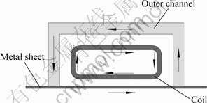
Fig. 1 Schematic diagram of uniform pressure coil
MANISH et al [9] used electromagnetic forces in two steps to make a good phone face. In the first step, a very fine surface detail was obtained by the uniform pressure electromagnetic actuator according to the features in the forming die. In the second step, the electromagnetic flanging was used to improve the molding depth of the phone. GOLOWIN et al [10] demonstrated that the uniform pressure actuator had the ability to form sheet metal with complicated shape and obtain fine surface features from the forming tool. MENG [11] used a plat spiral coil and a uniform pressure electromagnetic actuator to emboss a school mark. He found that better workpiece surface quality can be achieved using the uniform pressure electromagnetic actuator under vacuum condition. Therefore, the uniform pressure electromagnetic actuator can make it appropriate for many embossing or micro manufacturing application.
During the electromagnetic forming process, the reason for the coil failure is the bigger magnetic forces acting on the coil which makes the coil mechanically deform [12]. However, there are few literatures that predict the magnetic force on the sheet and the coil using a uniform pressure electromagnetic actuator. KAMAL [8] used the finite element software Maxweel to analyze the magnetic force distribution on the sheet. However, a two-dimensional finite element model was established, which cannot describe the current and magnetic force distribution on the sheet, coil and outer channel reasonably. And there are few literatures that predict the deformation law of the sheet using the uniform pressure electromagnetic actuator.
In this study, a three-dimensional finite element model is established to analyze the current and magnetic force distribution on the sheet, coil and outer channel using ANSYS/EMAG. The reason for the coil failure is analyzed in future. The magnetic forces on the sheet are input into an explicit finite element software ANSYS/LS- DYNA to analyze the deformation law of the sheet.
2 Flowchart of simulation method
The schematic flowchart of the simulation method is shown in Fig. 2 [13-14]. The current is divided into many steps. In each time step, ANSYS/EMAG is used to obtain the transient magnetic forces. The forces are saved as a unique file. Then the forces are used as boundary condition to simulate the high-velocity deformation of sheet with ANSYS/LS-DYNA in each time step.

Fig. 2 Flowchart of implemented algorithm
3 3D finite element models
3.1 Electromagnetic field model
The section of the uniform pressure coil and outer channel used to analyze the forming process is shown in Fig. 3 [11]. The three-dimensional electromagnetic model is shown in Fig. 4, which consists of far air region, air, sheet, outer channel and coil. The finite element meshes for the electromagnetic model are shown in Fig. 5. The regions which contain far air, sheet, outer channel and coil are meshed with Solid 97 element, an 8-node element. A thin annealed aluminum 1050 sheet is chosen [15]. The material parameters in electromagnetic field analysis are listed in Table 1.

Fig. 3 Schematic dimensions of section of uniform pressure coil

Fig. 4 Schematic diagram of 3D electromagnetic field model
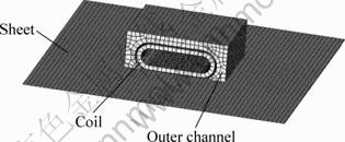
Fig. 5 Finite element meshes for electromagnetic modal
Table 1 Parameters of magnetic field analysis system

A 12-turn coil is placed on the top of the metal sheet. The separation distance between the sheet and the coil is 1 mm, and the thickness of the coil is 6 mm. The gap between single-turn is 2 mm. Current is loaded on the coil. It can be seen from Fig. 3 that the section of the coil is made up by straight line and circular arc. Therefore, local cylindrical coordinate system must be set to describe the current direction. The No.11 and No.12 local coordinate systems as well as the current direction in the coil are shown in Fig. 6.

Fig. 6 Simulation of current through coil: (a) Local coordinate system; (b) Current direction in coil
Figure 7 shows the current waveform which is divided into 10 time steps. The maximum current value is obtained at 46 μs.
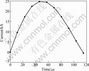
Fig. 7 Primary current used in analysis
3.2 Structural field model
The forces calculated by ANSYS/MEAG are used as boundary conditions to the ANSYS/LS-DYNA model, and an explicit dynamic finite element code is used in sheet deformation analysis. Compared to implicit algorithm, explicit algorithm avoids the computation of stiffness matrix and no possibility of convergence results. In the structure field model, the elements of coil, air and outer channel are set to null. During the forming process, the holder and the die are considered to be fixed and contact conditions are considered between the die and the sheet as well as the sheet and holder. The die has a diameter of 60 mm and a corner radius of 5 mm. In order to expedite the calculation speed, the elements of die are set to rigid body. Coulomb friction law is used with a friction coefficient of 0.25. Figure 8 shows the meshes of the die.
Figure 9 shows the flow stress―strain curve of the material under quasi-static condition [15].
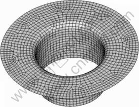
Fig. 8 Simulation of die meshed with 4-nodes quadrangular element
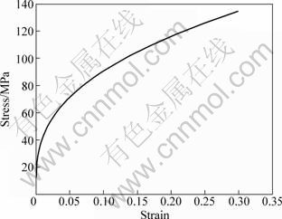
Fig. 9 True stress―strain curve of Al-1050
4 Simulation analysis
4.1 Magnetic forces analysis
Figure 10 shows the currents flow through the coil, sheet and outer channel. The current value is loaded at 10 μs on the coils. The clockwise current is put on the coil, and then the anticlockwise current is induced on the sheet and the internal surface of the outer channel. It agrees with the working principles of uniform pressure electromagnetic actuator shown in Fig. 1.
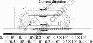
Fig. 10 Direction of current density in sheet, coil and outer channel
The current direction on the sheet is shown in Fig. 11. It can be seen that the region corresponding to the undersurface of the actuator projecting on the sheet has larger current density.

Fig. 11 Distribution of current density on sheet
Figure 12 shows the magnetic forces on the sheet at 46 μs. In the global Cartesian coordinate system, the nodes on the upper surface of the sheet along x axis and y axis are chosen. Figure 13 shows the distribution of the z axial magnetic forces. The region of the magnetic forces are mainly distributed in the location 40 mm away from the center along the y axis and the location 30 mm away from the center along the x axis. According to the section of the uniform pressure coil shown in Fig. 3, the region corresponding to the undersurface of the actuator projecting on the sheet has large magnetic forces.
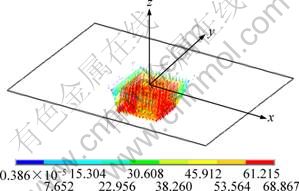
Fig. 12 Distribution of magnetic forces on sheet
A single-turn coil is chosen. The value and the direction of the magnetic force are shown in Fig. 14. The direction of the magnetic force is direct to the inner of the coil. The resin is used to improve the strength of the coil [11]. Therefore, the coil is difficult to deform inward. Since the magnetic forces on the upper area of the coil are stronger than those on the bottom of the coil, the bottom of the coil may be bulged.
Figure 15 shows the schematic diagram of the final profile of the sheet using a uniform pressure electromagnetic actuator. Assuming the coil has no deflection, with the deflection of the sheet increasing, the flux density at point A is bigger than that at point B, thus, the magnetic forces on the upper area are stronger than the ones on the bottom area. The resin plays a role in transferring the magnetic force from the upper area to the bottom area, thus, the bottom surface may be bulged. This is in agreement with the experimental results [11]. Figure 16 shows the bottom surface of the bulged uniform pressure electromagnetic actuator.
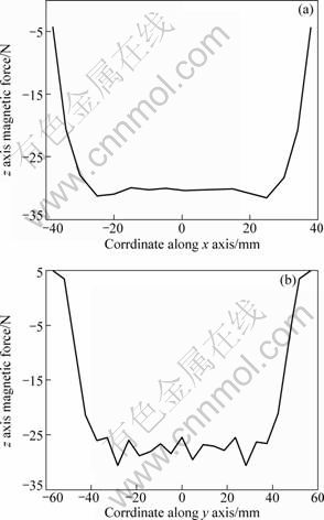
Fig. 13 Values of magnetic forces on sheet: (a) Magnetic forces along x axis; (b) Magnetic forces along y axis

Fig. 14 Distribution of magnetic forces on coil
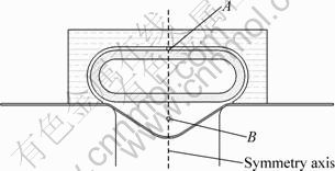
Fig. 15 Schematic diagram of final profile of sheet
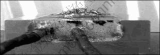
Fig. 16 Bottom surface of bulged coil [11]
The magnetic forces on the sheet are input into an explicit finite element software ANSYS/LS-DYNA, which is used to analyze the deformation law of the sheet. Figure 17 shows the profiles of sheet at different times. For the uniform pressure electromagnetic actuator, the displacement of the center sheet is equal to other region under the initial condition. With the time increasing, the displacement of the center node of the sheet is more than that of other regions. Traditional electromagnetic actuators are flat spirals that produce a nonuniform pressure distribution. The center sheet is formed by the inertial forces. Therefore, the deformation law of the sheet using traditional electromagnetic actuators is different from that using uniform pressure electromagnetic actuator [15-16]. However, the sheets have similar final profiles produced by the flat spiral coil and the uniform pressure electromagnetic actuator under a round die. If there is a die with a small depth, the uniform pressure electromagnetic actuator can be used to emboss in a designed shape.

Fig. 17 Change of profiles with time
5 Conclusions
1) The uniform pressure distributes in the region that corresponds to the undersurface of the actuator projecting on the sheet. Therefore, the coil conductor can be designed according to the wanted shape of the sheet.
2) The distribution of magnetic forces on the uniform pressure electromagnetic actuator is changed due to the increased distance between the coil and the sheet, which may cause coil failure.
3) The deformation law of the sheet is different between the traditional electromagnetic actuators and the uniform pressure electromagnetic actuator. However, the sheets have similar final profiles produced by the flat spiral coil and the uniform pressure electromagnetic actuator under a round die.
References
[1] OLIVEIRA D A, WORSWICK M J, FINN M, NEWMAN D. Electromagnetic forming of aluminum alloy sheet: Free-form and cavity fill experiments and model [J]. Journal of Materials Processing Technology, 2005, 170(1-2): 350-362.
[2] American Society for Metals. ASM metal handbook, Vol.14: Forming and forging [M]. Ohio: ASM International Handbook Committee, 1988: 1420-1425.
[3] HAN Fei, MO Jian-hua, HUANG Shu-huai. Theoretical study and application of electromagnetic forming technology [J]. Forging and Stamping Technology, 2006, 31(6): 4-8. (in Chinese)
[4] CORREIA J P M, SIDDIQUI M A, AHZI S, BELOUETTAR S, DAVIES R. A simple model to simulate electromagnetic sheet free bulging process [J]. International Journal of Mechanical Sciences, 2008, 50(10-11): 1466-1475.
[5] CHANG Hong, MENG Zheng-hua, HU Shuang-feng. Application and research of working coil used for sheet metal electromagnetic forming [J]. Forging and Stamping Technology, 2007, 32(3): 7-11. (in Chinese)
[6] CHU Hong-yan, FEI Ren-yuan, WU Hai-bo. Application research of elliptic working coil used in sheet electromagnetic forming [J]. Forging and Stamping Technology, 2002, 27(5): 38-41. (in Chinese)
[7] HUANG Shang-yu, CHANG Zhi-hua, WANG Zhong-ren, WANG Li-feng, YANG Mei. A finite-element analysis of electromagnetic sheet metal-expansion process [J]. Transactions of Nonferrous Metals Society of China, 1998, 8(3): 490-495.
[8] KAMAL M. A uniform pressure electromagnetic actuator for forming flat sheets [D]. Ohio: Department of Material Science and Engineering, The Ohio State University, 2005: 31-32.
[9] MANISH K, SHANG J, CHENG V, HATKEVICH S, DAEHN G S. Agile manufacturing of a micro-embossed case by a two-step electromagnetic forming process [J]. Journal of Material Processing Technology, 2007, 190(1-3): 41-45.
[10] GOLOWIN S, KAMAL M, SHANG J, PORTIER J, DIN A, DAEHN G S, BRADLEY J R, NEWMAN K E, HATKEVICH S. Application of a uniform pressure actuator for electromagnetic processing of sheet metal [J]. Journal of Materials Engineering and Performance, 2007, 16(4): 455-460.
[11] MENG Zheng-hua. The forming properties and constitutive equation research of magnesium alloy sheet under the HVF&Warm forming condition [D]. Wuhan: Wuhan University of Technology, 2009: 68, 120-124. (in Chinese)
[12] ZHAO Zhi-feng, LI Chun-feng, DENG Jiang-hua. The theory research on the magnetic pressure with the axisymmetric coil in electromagnetic bulging [J]. Journal of Plasticity Engineering, 2007, 14(3): 76-79. (in Chinese)
[13] LI Zhong, LI Chun-feng. Simulation of electromagnetic tube bulging based on loose coupling method [J]. Chinese Journal of Mechanical Engineering, 2006, 19(4): 566-569.
[14] BARTELS G, SCHATZING W, SCHEIBE H P, LEONE M. Comparison of two different simulation algorithms for the electromagnetic tube compression[J]. Int J Mater Form, 2009(S1): s693-s696.
[15] TAKATSU N, KATO M, SATO K, TOBE T. High-speed forming of metal sheets by electromagnetic force [J]. Japan Society of Mechanical Engineers, Internation Journal Part C, 1988, 31(1): 142-148.
[16] FENTON G K, DAEHN G S. Modeling of electromagnetically formed sheet metal [J]. Journal of Materials Processing Technology, 1998, 75(1-3): 6-16.
匀压力线圈作用下板料的磁场力分布和变形规律
崔晓辉,莫健华,肖师杰,杜二虎
华中科技大学 材料成形与模具技术国家重点实验室,武汉 430074
摘 要:根据已失效匀压力线圈的结构参数,分析板料、线圈、外部通道的电流和磁场力分布。结果表明:基于模拟结果的电流方向与匀压力线圈的工作原理一致。提出匀压力线圈失效的原因。然后将板料上的磁场力作为边界条件输入显式分析软件ANSYS/LS-DYNA,分析板料的变形规律。
关键词:电磁板料成形;磁场力;匀压力线圈;数值模拟
(Edited by FANG Jing-hua)
Foundation item: Project (50875093) supported by the National Natural Science Foundation of China
Corresponding author: MO Jian-hua; Tel: +86-27-877557174; E-mail: mjh@mail.hust.edu.cn
DOI: 10.1016/S1003-6326(11)61040-6

