
Synthesis of Y-junction carbon nanofibres by ethanol catalytic combustion technique
LI Fei(李 飞) 1,2 , ZOU Xiao-ping(邹小平) 1,2, CHENG Jin(程 进)1,2, ZHANG Hong-dan(张红丹)1,2, REN Peng-fei(任鹏飞) 1,2
1. Research Center for Sensor Technology, Beijing Information Technology Institute, Beijing 100101, China;
2. Beijing Key Laboratory for Sensor, Beijing 100101, China
Received 10 April 2006; accepted 25 April 2006
Abstract: Y-shaped structure was synthesized by ethanol catalytic combustion(ECC) technique on the copper plate substrate, without directly seeding catalyst into the flame. The as-grown Y-junction carbon nanofibres were investigated by transmission electron microscopy (TEM). The very common laboratory ethanol burner was used for synthesizing carbon nanofibres. Two kinds of the catalyst precursor, which are iron nitrate (Fe(NO3)3) and nickel nitrate (Ni(NO3)2), were respectively employed to assist the formation of Y-junction carbon nanofibres. TEM analysis confirm the formation of Y-junction in the coiled and noncoiled carbon nanofibres. The type of the catalyst is found to be crucial to grow different Y-junction carbon nanofibres. Different Y-shaped structure may possess different mechanical and electronic properties. These three-terminal nanofibres provide the nanoelectronics community with a novel material for the development of molecular-scale electronic devices.
Key words: carbon nanofibres; Fe(NO3)3; Ni(NO3)2; Y-junction; ECC; Raman spectra
1 Introduction
Since the discovery of carbon nanotubes in 1991 by IIJIMA[1], increasing interest has been attracted to the synthesis of Y-like carbon nanotubes, which might be important multi-terminal nanostructures for potential nanodevices such as single electron transistors[2], rectifying components and tunnel junctions as well as reinforcements for nanocomposites. For this purpose, Y-junctions have been as prototypes. To date, various fabrication methods have been developed to obtain the Y-type junctions carbon nanotubes. They include the arc-discharge process for complex branching junctions [3], template method[4,5], hot-filament CVD method using vaporated copper as the catalyst[6], and pyrolysis of hydrocarbon[7,8] or organometallic precursors along with thiophene[9,10]. In addition, nanowelding technique based on electron irradiation[11,12] also becomes one of the important methods to fabricate Y-junction carbon nanotubes.
The same applies to the Y-shaped junctions carbon nanofibers. For example, some groups have proved that nanofibres are more than an order of magnitude stronger than any current structure material, allowing revolutionary advances in lightmass, high-strength applications[13]. Therefore, Y-shaped nanofibres can be considered candidates to be the basic building unites for nanoeletronic devices. What’s more, the fullerenes C60 and C70 were firstly identified by the carbon vapor produced by laser irradiation of graphite, and have recently been produced in macroscopic quantities by vaporization of graphite with resistive heating. It has also been suggested that fullerenes might be formed in sooting flames. Their work motivated us to attempt to synthesize Y-junction carbon nanofibres, although there have been no practical devices made of real three-point nanofibre junctions hitherto.
In this work, we reported on an alternative way to synthesize Y-junction nanofibres with the stem and branches by ethanol catalytic combustion technique, which respectively use nickel nitrate precursor and iron nitrateprecursor as catalyst. Ethanol catalytic combustion technique is a simple and cheap method for synthesizing Y-junction carbon nanofibres. Compared to the above methods, it tenders several inherent advantages as follows. 1) The process of the synthesis can be done at the common laboratory; 2) Liquid ethanol, the very common laboratory fuel, can quite naturally provide both the elevated temperature and the hydrocarbon reactant for CNFs synthesis at atmospheric pressure; 3) The synthesis was carried out, allowing controllable residence time within a desired flame region; 4) The synthesis can also tender either extended flames or multiple flames for combustion, etc. Two kinds of catalyst that were nickel nitrate catalyst precursor and iron nitrate catalyst precursor were respectively employed to assist the formation of Y-shaped structures. Our results show the possibility of growing Y-junction carbon nanofibres by ECC.
Obviously, each method has its own advantages and disadvantages. Accordingly, in our present work, an ethanol flame is induced to synthesize Y-junctions. It provides a method that is much simpler, more economical to meet the future broad applications.
2 Experimental
The approach to grow Y-junction carbon nanofibres is based on ethanol catalytic combustion technique. The ethanol was employed as the carbon source and (Fe(NO3)3) or (Ni(NO3)2) as the catalyst precursor. The carbon nanofibres were synthesized by decomposition of ethanol. Firstly nickel nitrate was used as the catalyst precursor for the formation of Y-shaped structures. The first step is to prepare a saturated solution of the catalyst precursor. Some quantities of nickel nitrate were dissolved in the pure ethanol. And then the solution of catalyst precursor was sonicated for tens of minutes to form a suspension of catalyst. One drop of the saturated catalyst solution was applied with a dip-pen to the copper substrate, which was then placed in a flame without introducing any other gas for the nanofibre growth. The surface of the substrate was faced down against the flame when it was inserted into the central core of the flame. The substrate with catalyst precursor was combusted for several minutes and then carbon deposits accumulated on the copper plate. After a desired time, the sample was cooled to room temperature and dried in the air at room temperature. These deposits were removed and examined by transmission electron microscopy (TEM) with a JEOL 2010 microscope at 200 kV. The process of using iron nitrate as the catalyst precursor for synthesizing Y-junction is the same as that of using nickel nitrate. TEM was employed to confirm the structure of Y-junction.
3 Results and discussion
The TEM images reveal the presence of several kinds of Y-junctions. These images clearly show that the stem and the branches of the Y-junction are CNFs. The junction we synthesized doesn’t consist of a stem nanofibre connected two branch nanofibres. It seems that the branches grow from the sidewall of stem CNFs. Seen from the Fig.1(a) the diameter of the stem is the same as that of branches with a diameter of about 120 nm. However, it is interesting to note that the diameter of Y-junction as shown in Fig.1(d) is much larger than that of others. It can be thus concluded that there is a difference between the Y-junctions. Sometimes the difference is very large. Furthermore, we also noted that there is no catalytic particle present at junction point where branch nanofibres grow except for Fig.1(a). Fig.1 shows the different morphological Y-type junction structures.
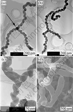
Fig.1 TEM images of Y-junctions of different structures using nickel nitrate as catalyst precursor
Fig.1(a) shows a spiral-shaped structure whose stem and branches are all coiled. A spherical amorphous particle is found right at the center of the junction (as marked by an arrow). Fig.1(b) shows the multiple Y-junction structure that has multiple Y-like junctions. Fig.1(c) shows the combinational structure that one of branches is noncoiled and others are helix. There is no catalyst precursor particle at the center of the junction. Fig.1(d) shows a Y-like junction that all three branches are noncoiled with no catalyst precursor particle.
Fig.1 also shows how multiple Y-junction can exit, suggesting possible multiple tunnel devices on a simple carbon nanofibre. Therefore, Y-junction CNFs is very useful in various fields of nanometer scale electronic applications such as interconnect, two terminal diodes, and three terminal transistors.
The same is true of using iron nitrate as the catalyst precursor to grow Y-type junctions as shown in Fig.2. However, the morphology of Y-junction is not abundant, which is just a single noncoiled structure.
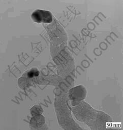
Fig.2 TEM image of Y-junction using iron nitrate as catalyst precursor
From Fig.1(a),Fig.1(c) and Fig.2, the mechanism seems to involve several steps. Firstly, a carbon nanofibre is formed from a nanosize catalyst precursor particle, and then a catalyst precursor particle is deposited on the surface of this nanofibre, which subsequently causes the growth of a new attached nanofibre, referred to as a ‘branch’. These two proceeding can, under specific circumstances, favor the growth of Y-branched nanofibres. The length of the branch could be the consequence of the reactivity of the catalyst[14], the concentration of the catalyst solution and growth temperature. Whereas, from the Fig.1(b), the Y-junction CNFs appear to grow by a tip-growth mechanism[14], that is, the catalyst precursor particles moved with the growing CNFs tip. The formation of Y-junction may be the result of changes in growth direction. Carbon atoms produced from the decomposition of ethanol molecules are firstly adsorbed on a catalytic precursor particle. They diffuse along the surface and/or in the interior of the metal particle, mainly due to the existence of concentration gradient along the diffusion path. As carbon atoms accumulate, a cap composed of the graphitic sheets forms. When the cap lifts off the catalytic precursor particle, a nanofibre is generated. As the fibre grows, a new cap may be formed due to carbon accumulation. The lifting off of the new cap will result in the formation of a new fibre. At the same time, in the case of a change in the direction of the concentration gradient, carbon atoms may accumulate and a cap may form at a different location on the surface of the catalytic precursor particle. As a result, the original fibre ceases extending, and a new fibre of different orientation starts to grow. The final formation of the Y-junction may result from the growth of a third fibre from a two-branch junction with the catalyst particle moved away from the junction[15]. From Fig.1(d), we propose a possible mechanism that the morphology of the CNF results from the flame perturbation during the growth of CNFs.
Raman spectroscopy is a simple and good tool for analyzing the structure of the Y-junction. Raman spectra of Y-junction CNFs were excited with the 514.5 nm line of a laser by a spectrometer at room temperature. Two peaks (1 345.5 cm-1 and 1 583.4 cm-1 in Fig.3; 1 349.8 cm-1 and 1 590.7 cm-1 in Fig.4) can be observed in the range of 1 200-1 700 cm-1 in a typical Raman spectrum, as shown in Figs.3 and 4. 1 250-1 450 cm-1 is the disorder-induced phonon mode (D-band), which is caused from the disordered components[16]. It has a high sensitivity to the disordered structures in carbon materials. 1 550-1 600 cm-1 is the graphite band (G-band) which is produced from the high degree of symmetry and order of carbon materials, and generally used to identify well-ordered CNTs[16]. The peak centered at 1 583.4 cm-1 and 1 590.7 cm-1 indicate a good arrangement of the hexagonal lattice of graphite. From Figs.3 and 4, we can clearly observe that the G-band (1 345.5 cm-1 and 1 349.8 cm-1) of the samplesis all higher than their D-band (1 583.4 cm-1 and 1 590.1 cm-1). This phenomenon shows that this sample is not up to a high graphitization degree.
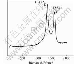
Fig.3 Raman spectrum of sample using Ni(NO3)2 as catalyst precursor
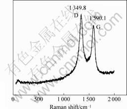
Fig.4 Raman spectrum of sample using Fe(NO3)3 as catalyst precursor
We further characterized the Y-junction nanofibres by high-resolution transmission electron microscope. A HRTEM image taken at the sample is shown in Fig.8. The image shows the stacking of the graphene sheets [17]. We can also clearly observe the lattice. But there are some defects on our samples, too.
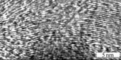
Fig.5 HRTEM image showing stacking of graphitic particles in sample using Fe(NO3)3 as catalyst precursor
A great deal of production of Y-like nanofibres is under investigation in our group. For further understanding of the behavior of the Y-junctions, the study of the microstructure of the region around the junction areas should be carried out.
4 Conclusions
Y-junction CNFs can be synthesized by the ethanol catalytic combustion technique by employing Fe(NO3)3) and (Ni(NO3)2 as catalyst precursor. In addition to, liquid ethanol can be successful used as a kind of carbon source for CNFs synthesis, too. Compared to CVD, pyrolysis and other methods, the catalyst does not need to be exteriorly added when using ethanol flame. TEM images confirmed that some of the synthesized Y-junction CNFs consist of three coiled CNFs with different diameters, and some of the synthesized Y-shaped junctions are made up of one noncoiled and two coiled CNFs; others are constituted of three noncoiled CNFs. Contrasting with the widely used CVD and other methods, the present method has the advantage of being much simpler and more economic. Thus, the technique is worthwhile to be developed. Further extensive research will be on the growth of well-aligned Y-junction CNFs and explore the possibility for mass-production.
References
[1] IIJIMA S. Helical microtubules of graphitic carbon [J]. Nature, 1991, 354: 56-58.
[2] ANDRIOTIS A N, MENON M, SRIVASTAVA D, CHERNOZATONSK I I. Ballistic switching and rectification in single wall carbon nanotube [J]. Appl Phys Lett, 2001,79: 266-268.
[3] ZHOU D, SERAPHIN S. Complex branching phenomena in the growth of carbon nanotubes [J]. Chem Phys Lett, 1995, 238: 288-289.
[4] PAPADOPOULOS C, RAKITIN A, LI J, VEDENEEV A S, XU J M. Electronic transport in Y-junction carbon nanotubes [J]. Phys Rev Lett, 2000, 85: 3476-3479.
[5] LI J, PAPADOPOULOS C, XU J. Growing Y-junction carbon nanotubes [J]. Nature, 1999, 402: 253-254.
[6] GAN B, AHN J, ZHANG Q, RUSLI, YOON S F, YU J, HUANG Q F, CHEW K, LIGATCHEV V A, ZHANG X B, LI W Z. Y-junction carbon nanotubes grown by in situ evaporated copper catalyst [J]. Chem Phys Lett, 2001, 333: 23-28.
[7] SU Lian-feng, WANG Jian-nong, YU Fan, SHENG Zhao-ming, Continuous dynthesis of Y-junction carbon nanotubes by catalytic CVD [J]. Chem Vap Deposition, 2005, 11: 351-354.
[8] LI W Z, WEN J G, REN Z F. Straight carbon nanotube Y-junctions [J]. Appl Phys Lett, 2001, 79: 1879-1881.
[9] SATISH KUMAR B C, THOMAS P J, GOVINDARAJ A, RAO C N R. Y-junction carbon nanotubes [J]. Appl Phys Lett, 2000, 77: 2530-2532.
[10] DEEPAK F L, GOVINDARAJ A, RAO C N R. Synthetic trategies for Y-junction carbon nanotubes [J]. Chem Phys Lett, 2001, 345: 5-10.
[11] TERRONES M, BANHART M F, GROBERT N, CHARLIER J C, TERRONES H, AJAYAN P M. Molecular junctions by joining single-walled carbon nanotubes [J]. Phys Rev Lett, 2002, 89: 075505-1-075505-4.
[12] CHENG J, ZOU X P, WANG L K. A simple synthesis of carbon nanofibers[A]. The New Progress on Nanomaterials Research and Technology Application[C]. Yantai, 2005. 71-75.(in Chinese)
[13] JIANG K, LI Q, FAN S. Spinning continuous carbon nanotube yarns [J]. Nature, 2002, 419: 801-801.
[14] ZHENG L X, O’CONNELL M J, DOORN S K, LIAO X Z, ZHAO Y H, AKHADOV E A, HOFFBAUER M A, ROOP B J, JIA Q X, DYE R C, PETERSON D E, HUANG S M, LIU J, ZHU Y T. Ultralong single-wall carbon nanotubes [J]. Naturematerials, 2004, 3: 673-675.
[15] SU L F, WANG J N, YU F, SHENG Z M. Continuous synthesis of Y-junction carbon nanotubes [J]. Chem Vep Deposition, 2005, 11: 351-354.
[16] LIU Y, PAN C X, WANG J. Raman spectra of carbon nanotubes and nanofibers prepared by ethanol flames [J]. J Mater Sci, 2004, 39: 1091-1094.
[17] SATISHKUMAR B C, JOHN THOMAS P, GOVINDARAJ A, RAO C N R. Y-junction carbon nanotubes [J]. Appl Phys Lett, 2000, 77: 2530-2532.
(Edited by LONG Huai-zhong)
Foundation item: Project(KM200510772013) supported by Beijing City Education Committee Science and Technology Development Program; Project(2005-2007) supported by Beijing City Education Committee Academic Innovative Team Program
Corresponding author: ZOU Xiao-ping; Tel: +86-10-64884673-812; Fax: +86-10-64879486; E-mail: xpzou2005@gmail.com

