Microstructure characteristic and formation mechanism of crackfree TaC coating on C/C composite
��Դ�ڿ����й���ɫ����ѧ��(Ӣ�İ�)2005���6��
�������ߣ������ ���� �Ʋ���
����ҳ�룺1206 - 1213
Key words��C/C composite; TaC coating; morphology; crack; mechanism; pore
Abstract: The microstructure characteristic and formation mechanism of the crackfree and ablation-resistant TaC coating deposited on the C/C composite by Chemical Vapour Deposition(CVD) were investigated, using the reaction system of TaCl5-C3H6-H2-Ar. The results show that the nanosized pore structure formed in the TaC coating interior during CVD process is the main factor to reduce the hardness, elastic modulus, linear expansibility and inner thermal stress. Then crackfree coatings can be prepared and their thermal shock resistance can be enhanced. To obtain the dense and homogeneous matrix surface is necessary for the crackfree and low stress coating. The TaC coating structure that distributes from the dense matrix towards loose coating surface will result in the thick crackfree coating with good thermal shock resistance.
Article ID: 1003-6326(2005)06-1206-08
LI Guo-dong(�����), XIONG Xiang(�� ��), HUANG Bai-yun(�Ʋ���)
(State Key Laboratory of Powder Metallurgy, Central South University,
Changsha 410083, China)
Abstract: The microstructure characteristic and formation mechanism of the crackfree and ablation-resistant TaC coating deposited on the C/C composite by Chemical Vapour Deposition(CVD) were investigated, using the reaction system of TaCl5-C3H6-H2-Ar. The results show that the nanosized pore structure formed in the TaC coating interior during CVD process is the main factor to reduce the hardness, elastic modulus, linear expansibility and inner thermal stress. Then crackfree coatings can be prepared and their thermal shock resistance can be enhanced. To obtain the dense and homogeneous matrix surface is necessary for the crackfree and low stress coating. The TaC coating structure that distributes from the dense matrix towards loose coating surface will result in the thick crackfree coating with good thermal shock resistance.
Key words: C/C composite; TaC coating; morphology; crack; mechanism; pore CLC
number: TQ050.4 Document code: A
1 INTRODUCTION
Carbon-carbon(C/C) composites are characterized by their low density, high strength at high temperature, excellent resistance to thermal shock, etc, which have been widely applied in aerospace fields. However, they are easy to be oxidized and ablated at high temperature and high speed gas jet with rapid ablation velocity exponential to pressure[1-5], which limits their potential for new type and high performance aerospace vehicles. To produce coatings that have good resistance to high temperature, oxidation, washout and ablation on the C/C composites becomes an important and successful method to improve the properties and applications of the composites[6-10]. TaC is one of the materials with highest melting point(3880-4000��[11, 12]), together with good resistance to oxidation at high temperatures (>2000��) and washout, and good chemical compatibility with C/C composites. So the TaC coating TaC is a perfect coating material for the nozzle and throat of C/C solid rocket motor(SRM).
Despite its advantages, the TaC has a large thermal expansion coefficient (6.7��10-6-8.2��10-6K-1), four times than that of C/C materials, and poor resistance to thermal shock. Thus it��s not suitable to use it directly as the
material for rocket nozzle that requires extreme reliability. Considering the tunable and designable structure of coatings prepared by CVD, the TaC can be deposited on the C/C composite surface as coatings to form new composite structure with good ablation resistance. Making full use of both the C/C composite stability at high temperature and TaC well resistant to washout and oxidation is vital to enhance the ablation resistance of the nozzle for C/C solid rocket motor(SRM). Accordingly, to prepare TaC coatings of high thermal stability on the C/C composites is the key technique for ablation resistant nozzles.
Based on the TaCl5-C3H6-H2-Ar active system, the TaC coating can be deposited on the C/C composite surface by CVD process. It��s found that the coating obtained tends towards crack and abscission, both transfixation cracks on the surface and interlaminar cracks in the interior being observed, which seriously influences the resistance of TaC to oxidation, washout and ablation. Remarkably, some single, crackfree and regular TaC coating were obtained in the experiment as well. In this paper, the microstructure and morphology of crackfree TaC coatings were investigated, and the formation mechanism of crackfree TaC coatings deposited on C/C nozzel surfaces with low stress and good ablation resistance was discussed.
2 EXPERIMENTAL
The TaC coating was prepared by CVD process with raw materials of TaCl5, C3H6, H2 and Ar, following the chemical equation as
TaCl5+C3H6+H2��TaC+HCl(1)
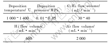
The experiment was carried out in the isothermal carbon tube furnace (electric power 60kW). The gas flow is indicated by glass rotameter, and the reaction gas flow of C3H6 and H2 is adjusted by gas-flow control system. TaCl5 solid powder is delivered with the carrier gas Ar by special implement from the deposition furnace bottom to CVD reaction furnace. The technological parameters for the CVD-TaC coating are shown in Table 1.
Table 1 Technological parameters for CVD-TaC coating
The experimental matrix is C/C composites with a density of 1.81g/cm3. The prefabricated carbon fiber is quasi-3D weaved integral felt, and the matrix carbon consists of CVI-pyrolytic carbon and resin carbon. The sample size is 30mm��20mm��3mm, and it��s polished by No.200 then No.600 waterproof abrasive papers, cleaned by ultrasonic for 30min, dried at 110�� for 2h, then weighed, charged and deposited.
The phase constitute of the TaC coating is measured by Japanese D/max2550VB+ X-ray diffractometer with rotating target, and the microstructure and morphology of TaC coating is observed by scanning electron microscope KYKY2800.
3 RESULTS AND DICUSSION
3.1 Structure of TaC coating with macrocracks
The main reason for the crack of TaC coating occurrence on the C/C surface is that the large difference of their expansion coefficient leads to severe thermal mismatch. Then the TaC coating deposited at high temperature exhibits large shrinkage on cooling. Due to the good compatibility between the TaC and C/C composite, the coating is tightly connected with the C/C matrix, then large tensile stress will occur on the coating surface. As the tensile strength of TaC is far less than its compression strength, the TaC coating will be easily cracked. Meanwhile, the deposition defects of TaC coating and the inhomogeneous thermal expansion of C/C matrix will also result in the appearance of cracks. The high value of elastic modulus will increase the crack possibility of the TaC coating as well. Thus, it is quite normal for cracks to appear on the single TaC coating.
Fig.1 shows the typical morphologies of TaC coatings with macrocracks. Such cracks are mainly of two types, one is the transfixation crack on surface, which is not so many in amount but long in length, transfixing the whole plane of the coating. When there exist carbon fibers parallel to the matrix surface, cracks perpendicular to the carbon fiber will be easily observed (Fig.1(a)); the other type of cracks is the interlaminar crack parallel to the matrix, which often occurs at 10-20��m from the matrix (Fig.1(b)), namely, when thicker coating was prepared, such cracks tend to exist and connect with the transfixation cracks of the coating surface.
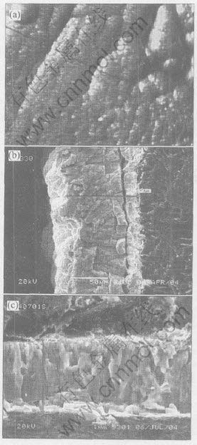
Fig.1 Typical morphologies of TaC coating with macrocracks
Due to the large difference of thermal expansion coefficient of carbon fibers in the radial direction and axial direction, the C/C composite possesses large expansion coefficient in the radial direction while zero or negative expansion coefficient in the axial direction, and accordingly the maximum thermal mismatch occurs between the fiber axial direction and TaC coating. It��s found that on the surface parallel to the carbon fiber, cracks easily appear vertical to the carbon fiber. Interlaminar cracks are resulted from the shearing stress concentration caused by thermal mismatch in thick coatings. Due to the pinning effect of coatings on the matrix surface, together with the stress buffer effect of amorphous and defect caused by lattice mismatch during the initial deposition, interlaminar cracks will hardly be observed within 10��m. The coating is tightly connected with the matrix as well. When applied as ablation resistant coatings at high temperature, the coating will tend towards large abscission because of interlaminar cracks, so such cracks are more destructive.
The common characteristics for the coating are that the TaC coating is mainly dense and well crystallized columnar crystals, with large grains and clear sintering pores among grains (Fig.1(c)). It suggests that during surface deposition, the coating interior undergoes the grain growth process similar to sintering. Such compact and large grain coatings have a thermal coefficient close to that of TaC polycrystals bulk ceramics, then high thermal mismatch will occur to form surface cracks and interlaminar cracks.
3.2 Structure and morphology of crackfree TaC coatings deposited at different temperatures
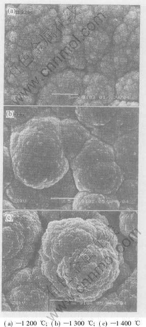
Fig.2 Surface mprphologies of TaC coatings deposited at different tempeatures
Fig.2 describes the surface morphologies of TaC coatings without macrocracks prepared at 1200-1400��. The different deposition temperatures lead to different morphologies. As seen in Fig.2(a), the TaC coating deposited at 1200�� is canliflower-like, and the primary particles can be clearly observed to be about 100nm, which are connected and agglomerated without obvious growth. Their structure is relatively loose with accumulation gaps among aggregates and no big pores. When deposited at 1300�� (Fig.2(b)), the coating is no longer canliflower-like with dense structure. Their primary particles disappear largely to grow into big particles (5-10��m). Obvious interfaces form among these big particles, and the sintering phenomenon of big particles swallowing smaller ones can be observed. The coating has no cracks, exhibiting typical CVD coating morphology of surfacial necleation and growth. Such structure is dense and homogeneous, without macrocracks and large microcracks, which is ideal for ablation resistant coatings. When deposited at 1400�� (Fig.2(c)), the coating exhibits another canliflower-like morphology. The size of primary particles is difficult to be recognized but they still exist. Primary particles merge each other into big ones, the big particles are dense without apparent gaps among them, and no sintering phenomenon can be observed among big particles. This is resulted from the principal effect of nucleation in gas phases at 1400��, and the agglomerating and growing phenomenon in gas phases[13]. Thus, this coating structure has lots of pores, weak connection with the coating interior, good buffer effect to thermal stress, and small thermal stress among particles. However, large particle gaps are unfit for the improvement of resistance to oxidation, washout and ablation for coatings.
The laser ablation experiment shows that[14, 15] the strong thermal shock at the initial 1-2s will lead to the local crack of the big particle surface in Fig.2(c), but the whole coating exhibits no abscission or breakup. While in Figs.2(a) and (b), neither particle nor the whole coating shows breakup, implying good resistance to thermal shock. The local breakup of dense big particles is mainly due to the large expansion coefficient of TaC, which results in poor thermal conductivity and strong stress concentration caused by the temperature difference from the surface to the interior.
3. 3 Fracture of crackfree TaC on C/C composite
Fig.3 shows the fracture SEM images of crackfree TaC coatings in thin or thick sizes. As determined from the coating��s XRD patterns (Fig.4), only diffraction peaks of TaC crystals can be observed in the two coatings, and no peaks belonging to CVD-C phase exist, which implies the TaC coatings obtained is quite pure. Combined with the energy spectrum analysis of the fracture (Fig.3(a)), it can be seen that the Ta element distributes fairly homogeneously.
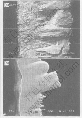
Fig.3 Fractures of crackfree TaC coating
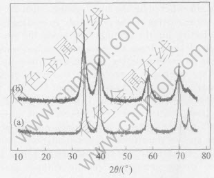
Fig.4 XRD pattern of TaC coating
Fig.3(a) describes the coating with thickness 314��m. It has no surfacial and interlaminar cracks, with loose surface and dense interior, and firmly connected with the matrix. From the matrix to surface, the coating can be sequentially divided into the fine-grained dense area (��150��m), coarse-grained dense area (150-250��m) and surface loose area (>250��m). The TaC structure is uniform in all areas and the three areas have no obvious transition interface.
Fig.3(b) represents the golden coating with good surface luster. The thin coating is about 10��m, of fine grains, dense and homogeneous, tightly connected with the matrix, and exhibits no surfacial and interlaminar cracks. As calculated by the FWHM (full width at half maximum) value of the XRD profile, the grain size is less than 120nm. The coating can well infiltrate the pits and micro-cracks on the matrix surface, so the pinning effect of coatings on the matrix can effectively restrain the occurrence of surfacial cracks.
3.4 Formation mechanism of crackfree TaC coating
3.4.1 Effect of pores or gaps in coatings
Fig.5(a) shows the surface SEM image corresponding to Fig.3(a), which is characterized by its preferential nucleation and growth. Despite the small size of primary particles in Fig.3(a) (about 100-200nm), the primary aggregate composed by them is about 2-8��m (small particles in large particles are named as secondary particles). The secondary aggregate (large particles) composed by primary aggregates reaches 50-100��m. The coating is mainly accumulated by the secondary aggregates of larger sizes, so many accumulation pores will appear inside the coating. The primary particle on the secondary aggregate surface has rather high reactivity, which can diffuse and merge into each other to form the coating with certain strength. However, the secondary aggregate has bigger particles and lower reactivity, so the pores caused by the secondary aggregate accumulation will not be filled up during the coating formation. Such porous coating has good thermal shock resistance and low thermal conductivity, exhibiting heat barrier effect on the coating surface. Though the strength and washout resistance of such structure is inferior to the dense coating, its heat barrier effect on the coating surface can well decrease the high thermal gradient suffered by the inner coating, then the inner dense coating can be protected. Accordingly, it is effective for the coating to prevent the occurrence of crack from the excessive surface tensile stress on cooling during preparation, the coating will not crack due to the excessive surface tensile stress; and the high thermal gradient (>2000��) during the nozzle operation. It has been proved by the laser ablation and oxyacetylene flame experiments that to design a single thick coating with loose surface transitional to dense interior is reliable[15]. It can resist the thermal shock up to 2300��/s, to guarantee TaC coating without crack, breakup and abscission.
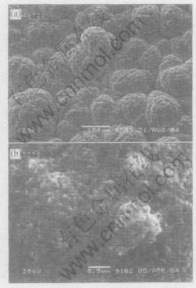
Fig.5 Surface morphologies of crackfree TaC coating
Fig.5(b) describes the surface SEM image corresponding to Fig.3(b) (also Fig.2(b)), exhibiting surface nucleation and growth. It can be seen that there homogeneously distribute many small pores less than 150nm on the coating surface. Due to the release, absorption and pinning effect of such pores on thermal stress, the TaC coating has no cracks at room temperature and can undergo the thermal shock at 2300�� without breakup. Though the primary particles have merged and disappeared, the primary aggregate tends to extinction, and apparent interface has formed among the second aggregates, there still exist many pores in nanoscale on the surface and interface of the secondary aggregates. This relies on the facts that during the primary particle merging and disappearing, the secondary particles composed of primary particles move towards and diffuse into each other. However the contraction and growth among secondary particles are inhomogeneous, then pores are left among some secondary particles, especially that many bigger pores will exist on the interface of secondary aggregates. With the deposition proceeding, surfacial pores become the inner enclosed ones, and the process filling pores by CVD will come to an end. Compared with the sintering temperature of TaC, the deposition temperature is much lower, similar to the low-temperature sintering of ceramics, so the pores among sintering necks is hard to be eliminated.
3.4.2 Formation mechanism of TaC coatings with low thermal stress
The maximum thermal stress �� of elastic materials has an approximate expression as
��= Ec��c(Tm-T)/(1-��c)(2)
where Tm is the average temperature and ��c is the Poisson��s ratio. It can be deduced that at a certain temperature, the thermal stress of coatings is determined by the elastic modulus Ec and linear expansibility ��c of the coating. For single crystals, these two factors and strength are constant, then the maximum thermal shock ��T subjected to it is fixed. While for porous ceramics and coatings, the elastic modulus Ec and expansion coefficient ��c are variable. To reduce the thermal stress and thermal shock resistance of the TaC coating, high strength, low elastic modulus and small expansion coefficient are expected. High strength requires highly dense microstructure of ceramics. The dense TaC has high elastic modulus Ec and large linear expansibility ��c, which will inevitably result in high thermal stress and low thermal shock resistance. Comparably, porous ceramics have small Ec and ��c, then the strength is low.
Fig.6 shows the fracture of TaC coatings. It can be seen from Figs.6(a) and (b) that the TaC coating prepared by CVD is acicular crystals, like pine branches growing alone the convex matrix. The whole coating is similar to fine crystal groups arranged like pine branches, only the sizes of crystal groups are different as caused by the uneven matrix and preferred orientation of TaC growth. Inside the crystal groups, homogeneous gaps in nanoscale can be observed. Certain pores exist among each crystal group and large slots are connected among loose arranged groups (Fig.5(b)). Such microstructure is resulted from fractal growth, the surface kinetics process for the TaC coating deposition[16, 17]. The fractal growth model is a typical deposition model that has a dominant probability for three dimensional island growth, while the probability for two dimensional layer growth is inferior. Between islands, pores without
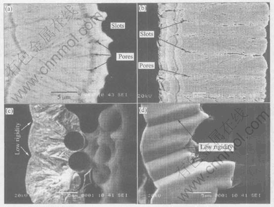
Fig.6 Fracture of porous TaC coating
atoms are easy to form in a size from atomic vacancy to nanometer, so certain pores or atom vacancies always exist inside each crystal group. Considering from thermodynamics, the growth reactivity and speed on the convexity are surely larger than that on the concave. During deposition, radial growing crystal groups on two neighboring convexities will confluence in the convex front. Due to the difference between growth directions of two groups, some pores will be generated in the merging site, or even connected slots (Figs.6(a) and (b)).
From the micro view, the coating is not really dense and homogeneous. Despite its high density and low pore ratio, the pore arrives at a high amount; from the macro view, the coating together with its defects, pores, etc, is statistically homogeneous. Such existence of many fine pores and vacancies without atoms can reduce the linear expansibility, elastic modulus and thermal conductivity of the coating, and increase its thermal shock resistance. Effects of many nanosized pores are better than big holes with the same porosity[18, 19]. Due to the elastic rigidity decrease caused by pores, the porous ceramic produces deformation energy less than that with fully compact structure. Also, the pinning effect of pores on cracks[20] is beneficial to reducing coating cracks.
Elastic modulus is determined by the chemical constitution of crystal and noncrystalline phases and the gross porosity[20], which will decrease with lower crystal phase ratio and higher porosity. The smaller the particle and the higher the strength, the lower the elastic modulus and the larger the yield stress maximum; then the toughness is increased and the hardness is decreased.
The effect that fine pores can reduce the elastic modulus and linear expansion can also be explained by the additivity of composites[20]. Due to the structural insensitivity of elastic modulus and linear expansion to mechanical properties, the pore or atomic vacancy and slot or gap among crystal groups can be regarded as the other phase in the material, namely phases with volume while without solid atoms. Then the TaC coating with statistically homogeneous fine pores can be regarded as diphase composites. As the pore phase has volume while without solid atoms, whose elastic modulus and linear expansion are zero compared with the solid, the additive two phases will reach lower values for the above two parameters.
Figs.6(c) and (d) represent the other two SEM images for the same TaC coating in Fig.3(b). Fig.6(c) shows the natural fracture, and radial acicular crystals along the carbon fiber surface are clearly observed. Fig.6(d) shows the fracture polished by diamond, which is fine grained, dense and relatively homogeneous. Such coating without cracks has good thermal shock resistance. On the two images, the low hardness region pattern on the coating agrees well with the matrix concave (see the marked porous region pattern on the matrix concave in Figs.6(a) and (b)). Based on the correspondence between CVD structure and deposition technique, the approximate technique results in similar structure. Then it��s deduced that the mechanism for the above phenomena is still the effect of fine pores and atomic vacancies that decrease both the elastic modulus and linear expansibility, only it has smaller grain and pore size that it is hard to discern. This coating has low deposition temperature and slow deposition rate. The deposition process happens on the matrix or coating, accompanied by surface absorption, desorption, diffusion and chemical reaction, instead of nucleation and growth in the space. The chemical reaction rate is slower than diffusion velocity, and then the primary particles obtained are fine in size forming acicular crystals on the surface. For the angle among radial acicular crystals resulted from neighboring convexities, it��s caused by the crystal preferred orientation. When the acicular crystals meet, they stop growing; while the ones that do not converge will continue their growth. At a high deposition temperature, both primary particle interfusion and sintering interface with certain pores and many atomic gaps or vacancies in the meeting region can be observed. Fig.2(b) describes the surface sintering interface. Due to the occurrence of pores and vacancies, this interface region has low density and hardness, so it will become concave pits when polished as sample shown in Fig. 6(d).
Another important condition to obtain crackfree coatings with low stress is the uniform and dense plane that needs coatings on the matrix, as well as the homogeneous distribution of nanosized pores in the coating. It��s found that cracks occur more easily in the coating deposited on C/C composites than that on graphite matrix. Due to the large difference between the radial and axial thermal expansions of carbon fibers, the C/C composite possesses different thermal expansions in various directions, and can be regarded as heterogeneous materials. It��s proved that when deposition on the C/C composite surface is parallel to the carbon fiber, transversal cracks easily appear vertical to the carbon fiber, while fewer cracks can be seen when deposition is perpendicular to the principal fiber surface. Such phenomenon is caused by the homogeneous distribution of both carbon fibers and pyrolysis carbon in the plane vertical to the principal fiber plane. The matrix of C/C composites prepared in three dimensions or more dimensions exhibits good homogeneity.
4 CONCLUSIONS
1) The formation of nanosized pores in the CVD process in the TaC coating is the main reason for the decrease of hardness, elastic modulus, linear expansibility and inner thermal stress, and the improvement of thermal shock resistance for preparing crackfree TaC coatings.
2) The smoothness of matrix surface can directly influence the microstructure and pore distribution of coatings. On the convex matrix, the coating grows fast with morphology similar to the acicular structure slanting upward. The pores are small and homogeneously distributed; on the concave matrix, the convergence site for coatings growing on the two neighboring convex matrix, the pores are larger and more, which are likely to be connected to form the region with low density and hardness.
3) The TaC structure that is from dense to loose in positions from the matrix to coating surface can result in the crackfree coating with good thermal shock resistance.
REFERENCES
[1]Bacos M P, Dorvaux J M, Lavigne O, et al. C/C composite oxidation model ��: Morphological experimental investigation [J]. Carbon, 2000, 38: 77-92.
[2]Bacos M P, Dorvaux J M, Lavigne O, et al. C/C composite oxidation model ��: Oxidation experimental investigations [J]. Carbon, 2000, 38: 93-103.
[3]Bacos M P, Dorvaux J M, Lavigne O, et al. C/C composite oxidation model ��: Physical basis, limitations and applications [J]. Carbon, 2000, 38: 104-116.
[4]YI Fa-jun, LIANG Jun, MENG Song-he, et al. Study on ablation mechanism and models of heatshield composites [J]. Journal of Solid Rocket Technology, 2000, 23(3): 48-56.(in Chinese)
[5]WANG Shi-ju, AN Hong-yan, CHEN Yu-mei, et al. Study on oxidation of carbon/carbon composite [J]. Ordnance Material Science and Engineering, 1999, 22(4): 36-40.(in Chinese)
[6]Gozzi D, Gzzardi G, Montozzi M, et al. Kinetics of high temperature oxidation of refractory carbides [J]. Solid State Ionics, 1997(101-103): 1243-1250.
[7]Patterson M C L, He S, Fehrenbacher L L, et al. Advanced HfC-TaC oxidation resistant composite rocket thruster [J]. Materials and Manufacturing Processes, 1996, 11(3): 367-379.
[8]CHENG Lai-fei, ZHANG Li-tong, XU Yong- dong, et al. Preparation of a multi layer coating for carbon carbon composites [J]. Journal of Northwestern Polytechnical University, 1998, 16(1): 129-132.(in Chinese)
[9]CUI Hong, SU Jun-ming, LI Rui-zhen, et al. On improving anti-ablation property of multi-matrix C/C to withstand 3700K [J]. Journal of Northwestern Polytechnical University, 2000, 18(4): 669-673.(in Chinese)
[10]Chihiro K, Tadashi L. Carbon fiber-reinforced composite material having a gradient carbide coating [P]. US 5254397.1993-10-19.
[11]YE Da-lun, HU Jian-hua. Practical Thermodynamic Data Mnnual for Inorganic Matter [M]. Beijing: Metallurgical Industry Press, 2002.(in Chinese)
[12]MA Fu-kang, QIU Xiang-dong, JIA Hou-sheng, et al. Niobium and Tantalum [M]. Changsha: Central South University Press, 1997.
[13]Fendler J H. Nanoparticles and Nanostructured Films [M]. Weinheim: Wiley-vch Press, 1998.
[14]LI Guo-dong, XIONG Xiang. Study on ablation character of TaC coating by low power laser [J]. Journal of Material Science and Engineering of Powder Metallurgy, 2005, 10(3): 155-159.(in Chinese)
[15]LI Guo-dong, XIONG Xiang, HUANG Bai-yun. Effect of temperature on composition, surface morphology and microstructure of CVD-TaC coating [J]. The Chinese Journal of Nonferrous Metals, 2005, 15(4): 565-571.(in Chinese)
[16]WANG En-ge. Atomic-scale study of kinetics in film growth(��) [J]. Progress in Physics, 2003, 23(1): 1-61.
[17]XIN Hou-wen. Reaction Kinetics in Fractial Media [M]. Shanghai: Scientific and Technological Education Press, 1997.
[18]SHEN Jun, ZHOU Bin, WU Guang-ming, et al. Preparation and investigation of nanoporous super thermal insulation: silica aerogels [J]. The Chinese Journal of Process Engineering, 2002, 2(4): 341-345.(in Chinese)
[19]GU Ping, MIAO Hong, LIU Zhao-tao, et al. Elastic modulus of nanoporous alumina films through bulge test [J]. Journal of Experimental Mechanics, 2004, 19(1): 34-38.
[20]Brook R J. Processing of Ceramics Part ��(Materials Science and Technology, Vol.17A) [M]. Weinheim: VCH Verlagsgellschaft mbH, 1996.
(Edited by PENG Chao-qun)
Foundation item: Project(2002AA305207) supported by the National High-Tech Research and Development Program of China; Project(03JJY3073) supported by the Natural Science Foundation of Hunan Province; Project(D200525004) supported by the Education Foundation of Hubei Province
Received date: 2005-07-06; Accepted date: 2005-09-10
Correspondence: LI Guo-dong, PhD Candidate; Tel: +86-731-8836864, +86-13087317973; E-mail: lgd63@163.com

