
Ultrasonic characterization of modified Cr2O3 coatings by reflection coefficient spectroscopy
LI Ji-cheng(李继承)1, LIN Li (林 莉)1, LI Xi-meng(李喜孟)1, LI Guang(李 光)2, LEI Ming-kai(雷明凯)3
1. Nondestructive Testing and Evaluation Laboratory, School of Materials Science and Engineering,
Dalian University of Technology, Dalian 116024, China;
2. Department of Mechanical Engineering, Beijing Institute of Graphic Communication, Beijing 102600, China;
3. Surface Engineering Laboratory, School of Materials Science and Engineering,
Dalian University of Technology, Dalian 116024, China
Received 24 March 2009; accepted 13 July 2009
Abstract: Pores, microcracks and density of plasma sprayed Cr2O3 coatings before and after high-intensity pulsed ion beam (HIPIB) irradiation were investigated using the ultrasonic reflection coefficient spectroscopy (URCS). The URCS was analyzed based on an acoustic transmission model for the multi-layered structure. The longitudinal velocity in the coatings was calculated from the experimental URCS, and the attenuation coefficient expression was deduced by comparing the experimental and numerical fitting amplitude spectral lines. The longitudinal velocity of as-sprayed Cr2O3 coating is 2 002 m/s, and increases to 2 099 and 2 148 m/s after being irradiated by HIPIB with 1 and 5 shots. Correspondingly, the factor A changes from 0.046 to 0.026 and 0.020 and n from 1.702 to 1.658 and 1.649 in the attenuation coefficient expression of α=Af n. It is observed that the surface morphology of Cr2O3 coatings changes from rough and porous to smooth and uniform with the increase of shot number, which accords with the ultrasonic analyses reasonably. The URCS seems to provide a convenient and nondestructive method to characterize surface modification of the plasma sprayed coatings.
Key words: ultrasonic characterization; Cr2O3 coating; high-intensity pulsed ion beam; ultrasonic reflection coefficient; attenuation coefficient
1 Introduction
Ceramic coatings deposited by plasma spray are widely used to improve the high-temperature oxidation resistance and wear resistance of metallic materials[1-2]. The lamellar grains in air plasma sprayed coatings pile up on the undulating interfaces. The interfaces including inter-“splat” boundaries and non-bonded interfaces are parallel to the metal/ceramic interface with 15%-25% (volume fraction) porosity. This generally leads to short thermal-cycling life due to proliferation of the microstructural defects and the roughness of interface[1]. So, surface sealing is required to form the uniform and compact outer surface of the coatings. Various post-treatment technologies, such as laser remelting[3-4], solar energy treatment[5], and phosphate impregnation[3], were employed to form a dense layer on the ceramic surface. Much recently, a high-intensity pulsed ion beam (HIPIB) technique has been utilized to modify ceramic coatings as demonstrated on plasma sprayed Cr2O3 coatings on heat-resistant steel[6-7]. Due to the shallow range of 0.1-10 μm and high energy density of 1-50 J/cm2, HIPIB becomes an ideal flash-heat source to rapidly melt and/or vaporize the near surface layer of materials at typical high heating and cooling rate of 107-1010 K/s with pulse duration less than 1 μs[8-9]. Compared with laser processing, HIPIB can irradiate sample with an area of hundreds of squared centimeters per pulse. This allows for surface modification with few shots. MIAO and LEI[10] used the HIPIB with the ion current density of 300-500 A/cm2 and a shot number of 1-10 to irradiate plasma sprayed Cr2O3 coatings on heat-resistant steel and obtained a compact surface with a continuous layer of 1-2 μm thick due to remelting of the lamellar grains on the coating.
At present, a series of optical, mechanical, and electrochemical methods, such as scanning electron microscopy (SEM), scratch test, and nanoindentation test[11-13], are used to examine the change of morphology, microstructure, and mechanical properties of the coatings. A suitable nondestructive technique with capability to provide reliable and reproducible quantitative information for coatings has obvious advantages. Some work based on the ultrasonic method has been performed on various coatings[14-18]. The ultrasonic propagation mechanism in homogenous and isotropic coatings has been generally established[19]. While for the inhomogeneous and anisotropic coatings, due to a large amount of pores and microcracks randomly in a lamellar or columnar structure, the mechanisms such as ultrasonic propagation, scatter and absorption attenuation still remain unclear. Investigating the ultrasonic reflection coefficient in frequency domain becomes an important method to evaluate the properties of coatings.
Since the ultrasonic propagation mechanism in inhomogeneous and anisotropic coatings is very complicated, using single parameter cannot provide data for all the properties. Previous researches have indicated that the low acoustic velocity of plasma-sprayed coatings appears to be linked with a large attenuation coefficient[15]. In this work, ultrasonic velocity and attenuation coefficient are combined to evaluate the properties such as pores, microcracks and density of the as-sprayed and HIPIB irradiated Cr2O3 coatings.
2 Experimental
2.1 Samples preparation and microstructure characterization
The Cr2O3 coatings were directly air plasma sprayed on 9 pieces of cleaned and grit blasted (Corundum, 60 grit) heat-resistant steel (C 0.10, Mn 1.50, Si 0.80, Cr 18.00, Ni 9.00,Ti 0.80, P 0.035, S 0.030 and Fe balance, mass fraction, %) substrates (30 mm×50 mm×5 mm) using a plasma spray equipment (MeTco-Plasma 9MB, USA). The sprayed Cr2O3 powder has a particle size of 20-40 μm. The HIPIB irradiation with 1 and 5 shots was carried out in a TEMP-6 type HIPIB apparatus operating in unipolar mode on 6 pieces of samples, 3 for each kind of shot. The apparatus is mainly comprised of a Marx generator, a double coaxial pulse-forming line (PFL) with two gas switches based on gas self-healing breakdown, a magnetically insulated ion diode (MID) by external-magnetic field and a target unit in vacuum chamber[20]. The main ion species used for HIPIB were approximately 30% C+ and 70% H+. The ion energy and ion energy density were 300 keV and 0.1-5 J/cm2, respectively. The irradiated Cr2O3 coatings were imbedded vertically in epoxy resins perpendicular to polish plane for cross-sectional observation. The morphology on the ablated surface and cross-section of the as-sprayed and irradiated Cr2O3 coatings were observed by using a JSM-5600LV SEM.
2.2 Principles
The general solution for the complex coefficient of acoustic pressure at normal incidence to a single layer has been given as[19]
 (1)
(1)
where k2z is the wave number in Z direction; d is the coating thickness; V23 and V12 are the reflection coefficients at the individual layer boundaries, as shown in Fig.1. For an attenuating layer, k2z is complex, and of the form k2z=k+iα, where k is the wave number, k=2πf/c2. f is the frequency and c2 is the longitudinal velocity in the layer. α is the attenuation of the layer in nepers per unit length. From the complex reflection coefficient of Eq.(1), the amplitude of reflection coefficient |V(f)| may be obtained:

 (2)
(2)
Eq.(2) has shown that the value of |V(f)| is related with the frequency f, thickness d, velocity c2, and impedance of the media 1, 2, and 3, as shown in Fig.1.

Fig.1 Diagram of ultrasonic reflection and transmission in three media embedded thin layer
When f, d, and c2 meet the expression sin2(2πfd/c2)=1,|V(f)| obtains a series of minima and the values at the minima are given by
 (3)
(3)
Thus, the frequency interval Δf between the minima could be expressed by the following equation:
 (4)
(4)
If d is known, c2 could be deduced from Eq.(4) according to the frequency interval Δf of the experimental line of ultrasonic reflection coefficient.
Furthermore, the expression for the attenuation coefficient α and its value could be obtained based on the comparison between the experimental and the numerical fitting lines of |V(f)| as follows. Firstly, the expression, α=Afn, is determined according to the ultrasonic attenuation mechanism in solid bulk medium and in coating medium[17]. Secondly, for Eq.(2), V12 and V23 are calculated on the basis of values of ρ1, ρ3, c1 and c3, where d is known and c2 could be determined from Eq.(4). Thus, |V(f)| is only dependent on the value of α, and the numerical fitting line could be plotted directly. Finally, by adjusting the values of A and n, perfect agreement between the experimental and numerical fitting line of |V(f)| can be obtained.
2.3 Ultrasonic measurements
The immersed focus pulse-echo technique with moderate pulse width was chosen[21]. The excitation and collection of ultrasonic signals were fulfilled by GE USIP40 ultrasonic flaw detector. The focusing transducer was used to generate and receive ultrasonic pulses. The diameter of the crystal is 6.4 mm and the nominal frequency is 16 MHz. The observations of waveforms and data sampling were accomplished by oscilloscope Tektronix 4 000, and spectral analysis technique was utilized to process time signals. A reference wave was recorded using an identical heat-resistant steel block without Cr2O3 coating on its surface. The sampling frequency is 500 MHz and the duration of waveform is about 0.2 μs.
In order to improve the directivity of acoustic beam, enhance the testing sensitivity and resolution, focusing the beam with special transducer was adopted. The focal length and focal zone length of the focusing transducer are 50 mm and 22.6 mm, respectively. The location of the transducer was adjusted until the focal zone center was located on the front surface of the coating sample. The focal zone length was much larger than the coating thickness, which ensured that the coatings could be entirely covered in the focal zone.
3 Results and discussion
Fig.2 shows the surface morphologies of the as-sprayed and irradiated Cr2O3 coatings by HIPIB with 1 shot and 5 shots. The typical surface morphology of rough and porous surface formed by the wavy pile-up of the irregular grains with a pan-cake-like splat structure was observed on the as-sprayed Cr2O3 coating (Fig.2(a)). The surface remelting by 1 shot irradiation led to a rounding of the sharp edges and protrusions on the irregular grains (Fig.2(b)). The small enlarged splats were reformed by a combination of the splat melting and cavity sealing, which caused a partially compact surface. By increasing the shot number up to 5, the serious surface melting and ablating caused more large splats, which reformed by the melting of all small grains and partially large grains and the remelting of splats (Fig.2(c)).
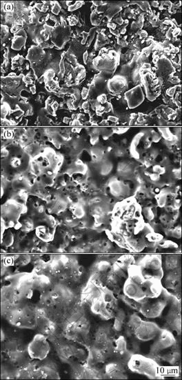
Fig.2 Surface morphologies on as-sprayed (a) and irradiated Cr2O3 coatings by HIPIB with 1 shot (b) and 5 shots (c)
Fig.3 presents the cross-sectional SEM images of the as-sprayed and irradiated Cr2O3 coatings by HIPIB with 1 shot and 5 shots, respectively. The typical morphology of as-sprayed coating revealed an obvious lamellar structure with many cavities (Fig.3(a)). After HIPIB irradiation with 1 shot, a thin discontinuous remelted layer of about 1.5 μm near the surface was observed, which was generated by the locally reformed splats (Fig.3(b)). And an apparently compact structure in the matrix coating was formed due to an impact effect of HIPIB irradiation. After 5 shots, the grains melting became serious; and the surface melting and ablating caused the more large splats (Fig.3(c)). In the local area, the individual reformed splats were agglomerated together. As a result, relatively smooth and uniform surface was produced though a few microcracks were observed.

Fig.3 Cross-sectional morphologies of as-sprayed (a) and irradiated Cr2O3 coatings by HIPIB with 1 shot (b) and 5 shots (c)
Figs.2 and 3 indicate that the as-sprayed coating presents rough and porous surface in a cross-sectional view. After 1 shot, the impact effect of HIPIB irradiation and the formation of the thin remelted layer bring an apparently compact structure. After 5 shots, enlarged irradiation effects cause denser microstructure. The modification of the coatings could be further verified from measurement of the hardness. MIAO and LEI[10] reported that the densification of top layer under remelting and ablation leads to an increase of microhardness from HV1.96N 9.82 GPa on as-sprayed coating to HV1.96N 10.37 GPa on 1 shot and HV1.96N 23.41 GPa on 5 shots irradiated surface.
Fig.4 illustrates the ultrasonic pulse echoes from the as-sprayed coating and irradiated Cr2O3 coatings with 1 shot and 5 shots. The coating is so thin that the front and back echoes from the layer overlap and it is hard to differentiate the waveforms from each other. The ultrasonic reflection coefficient spectroscopy (URCS) was obtained through Fourier transform with Origin 6.0 Professional software, as shown in Fig.5. Two specific amplitude minima could be observed in all the three experimental lines, which resulted from the interference of the front and back echoes of the coating. The value of the longitudinal velocity could be deduced from the frequency interval of the minima based on the coating thickness. In addition, ultrasonic attenuation mechanism could be inferred from the minima of the URCS. For the as-sprayed Cr2O3 coating, the minima occur at 12.21 and 32.23 MHz, respectively. With 1 shot, they are 12.70 and 33.69 MHz, and with 5 shots they are 11.23 and 32.71 MHz, respectively. The frequency intervals between the two minima are 20.02, 20.99, and 21.48 MHz. The thickness of coatings was measured from the cross-sectional morphology given in Fig.3. Since the thickness was not very uniform, 50 μm was used as an average value. According to Eq.(4), to calculate the ultrasonic velocity for the Cr2O3 coatings with the average thickness of 50 μm, the ultrasonic velocity of the as-sprayed coating is 2 002 m/s and increases to 2 099 and 2 148 m/s after HIPIB irradiation with 1 shot and 5 shots, as shown in Fig.6. The measurement error could be deduced to be ±12.2 m/s, which is mainly from the precision of the frequency interval. The increase of the velocity is caused by the compactness and uniformity of the top layer microstructure of irradiated coatings. With the increase of shot number, the coating seems packed. The increase of microhardness implies the enhancement of the coating stiffness. The two factors contribute to the increase of the coating velocity.
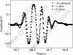
Fig.4 Ultrasonic pulse echoes of as-sprayed and irradiated Cr2O3 coatings by HIPIB with 1 shot and 5 shots
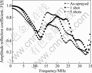
Fig.5 Experimental URCS results of as-sprayed and irradiated Cr2O3 coatings by HIPIB with 1 shot and 5 shots

Fig.6 Ultrasonic velocity of as-sprayed and irradiated Cr2O3 coatings by HIPIB with 1 and 5 shots
Attempts to determine the expression and value of the attenuation coefficient α were made, leading to best fit between the theoretical and experimental lines of the reflection coefficient spectra. According to the ultrasonic attenuation theory in the solid bulk medium and the coating medium[17], the expression α=Afn was selected. The factor A contains the effects of microcrack, pore, grain size, anisotropic factor, and heterogeneity, etc. The factor n implies the ratio of the ultrasonic wavelength to the size of the scatter. The values of the density and velocity of water (medium 1) and substrate (medium 3), as shown in Fig.1 were measured experimentally. The water density ρ1 was measured with photoelectric analytical balance and volumetric cylinder. On the basis of Archimedes’ principle, the density of heat-resistant steel ρ3 was obtained. The velocities c1 and c3 were determined by using ultrasonic pulse-echo reflection method[16]. Each measurement was replicated ten times. The experimental data and standard deviations are given in Table 1. The experimental and numerical fitting lines of the URCS are illustrated in Fig.7. General agreements experimental and numerical fitting lines was also observed for the as-sprayed and 1 shot irradiated coatings. Correspondingly, the expressions of the attenuation coefficient used to fit the URCS were obtained, α=0.046f1.702, α=0.026 f1.658, and α=0.020 f1.649 (where f is in MHz).
Table 1 Experimental data of density and velocity


Fig.7 Experimental and fitting lines of URCS of as-sprayed (a) and irradiated Cr2O3 coatings by HIPIB with 1 shot (b) and 5 shots (c)
For the as-sprayed Cr2O3 coating, pores and microcracks disperse in the matrix and near the top layer, which causes significant loss of ultrasonic energy. The factors A and n are 0.046 and 1.702, respectively. After 1 shot and 5 shots, the factor A decreases significantly to 0.026 and 0.020, and that of n decreases slightly to 1.658 and 1.649. The SEM images of the irradiated Cr2O3 coatings show that the splat melting and cavity sealing produce the small enlarged splats and a partially compact surface when the HIPIB is irradiated to the as-sprayed Cr2O3 coating. Less pores and microcracks are helpful to decreasing the ultrasonic scatter attenuation. The modification of the coating microstructure becomes more significant with increasing shot number up to 5, where denser microstructure with fewer defects further reduces the ultrasonic scatter, as compared with the case of 1 shot irradiation. To investigate the relation between the frequency and the attenuation coefficient, attenuation coefficient spectra of the as-sprayed and irradiated Cr2O3 coatings are shown in Fig.8. It is observed that the attenuation coefficient increases with the frequency as predicted by ultrasonic attenuation theory.

Fig.8 Relationship between ultrasonic attenuation and frequency in as-sprayed and irradiated Cr2O3 coatings by HIPIB with 1 and 5 shots
The velocity in coatings is usually much lower than that obtained for the dense materials with the same composition due to a large amount of pores and low elastic modulus from the coatings. LESCRIBAA and VINCENT[15] have found that the acoustic velocity in plasma-sprayed materials was very low in comparison with that obtained for dense solid bulks. For example, for sintered ZrO2-8%Y2O3 (mass fraction) zirconia they have found an ultrasonic velocity of 6 870 m/s, much higher than the plasma-sprayed zirconia coatings, 2 750 and 4 000 m/s. RICHARD et al[16] measured the longitudinal velocity of plasma-sprayed Cr2O3 coatings to be (6 289±1 024) m/s. For the as-sprayed and irradiated Cr2O3 coatings by HIPIB, the longitudinal velocity changes from 2 099 to 2 148 m/s, much lower than the usual values of dense bulk ceramics, 6 000- 10 000 m/s.
The low acoustic velocity of plasma-sprayed materials seems to be linked with a large attenuation coefficient. High volume pores and microcracks, serious anisotropy and heterogeneity should be the main reasons for the significant ultrasonic attenuation. HAINES et al[17] reported the ultrasonic characterization for a thin layer of epoxy cast on an aluminum block and a Fe3O4 layer on mild steel. Excellent agreements between the experiment and theory were achieved by presenting α=0.11f for the epoxy and α=0.078f (where f is in MHz) for the Fe3O4. However, the disagreement between the theoretical and experimental frequency interval of URCS minima implies that the attenuation varies with frequency according to a power law, somewhere between f and f2. LESCRIBAA et al[15] obtained the attenuation coefficient of 45 and 12 dB/cm at 3 MHz for two ZrO2-8%Y2O3 (mass fraction) coatings prepared by different methods. For the as-sprayed and irradiated Cr2O3 coatings by HIPIB, according to the attenuation coefficient expressions mentioned above, the attenuation coefficients were 25.9, 14.0, and 10.6 dB/cm, respectively, at the same frequency of 3 MHz; and the factor n in the expression α=Afn changes from 1.702 to 1.658 and 1.649. Although ultrasonic propagation and attenuation mechanisms in the coatings have not been totally established, URCS shows distinct potential on the characterization of the coating properties.
4 Conclusions
1) The expression of ultrasonic reflection coefficient for attenuating layer embedded in three layered medium is deduced, which provides a foundation for the investigation of longitudinal velocity and attenuation coefficient of Cr2O3 coatings.
2) The longitudinal velocity of as-sprayed Cr2O3 coating is 2 002 m/s, and increases to 2 099 and 2 148 m/s after being irradiated by HIPIB with 1 shot and 5 shots.
3) The ultrasonic attenuation coefficient of Cr2O3 coatings decreases with the shot number increasing. According to the sequence of as-sprayed coating, 1 shot and 5 shots irradiated Cr2O3 coatings, the factor A changes from 0.046 to 0.026 and 0.020, and n from 1.702 to 1.658 and 1.649 in the expression of α=Afn.
4) HIPIB irradiation decreases pores and microcracks, and improves uniformity and heterogeneity of the plasma sprayed coatings, which contributes to the increase of the longitudinal velocity and the decrease of the attenuation coefficient.
Acknowledgements
The authors are grateful to Dr. S. M. MIAO of Dalian University of Technology, China, for his contribution in the samples preparation and SEM analysis.
References
[1] PADTURE N P, GELL M, JORDAN E H. Thermal barrier coatings for gas-turbine engine applications [J]. Science, 2002, 296: 280-284.
[2] EVANS A G, MUMM D R, HUTCHINSON J W, MEIER G H, PETTIT F S. Mechanisms controlling the durability of thermal barrier coatings [J]. Progress in Materials Science, 2001, 46(5): 505-553.
[3] AHMANIEMI S, VUORISTO P, MANTYLA T, GUALCO C, BONADEI A, MAGGIO R D. Thermal cycling resistance of modified thick thermal barrier coatings [J]. Surface and Coatings Technology, 2005, 190(2/3): 378-387.
[4] ANTOU G, HLAWKA F, CORNET A, BECKER C, RUCH D, RICHE A. In situ laser remelted thermal barrier coatings: Thermophysical properties [J]. Surface and Coatings Technology, 2006, 200(20/21): 6062-6072.
[5] FERRIERE A, LESTRADE L. Solar processing for the glazing of ZrO2-Y2O3 thermal barrier coatings: Reduction of crack initiation [J]. Journal of Solar Energy Engineering, 2002, 124(3): 315-317.
[6] ZHU D M, MILLER R A, NAGARAJ B A, BRUCE R W. Thermal conductivity of EB-PVD thermal barrier coatings evaluated by a steady-state laser heat flux technique [J]. Surface and Coatings Technology, 2001, 138(1): 1-8.
[7] ZHU Xiao-peng, LIU Chen, HAN Xiao-guang, LEI Ming-kai. Changes in surface morphology of Ti6Al4V alloy and ZrO2-Y2O3 ceramic coating modified by high-intensity pulsed ion beams [J]. Frontiers of Materials Science in China, 2008, 2(1): 55-59.
[8] ZHANG J L, TAN C, WANG W C, WANG Y N. A spectroscopic scheme to measure the expansion velocity of ablation plasmas formed by high intensive pulsed ion beam [J]. Vacuum, 2004, 73(3/4): 673-679.
[9] WANG X, HAN X G, LEI M K, ZHANG J S. Effect of high-intensity pulsed ion beams irradiation on corrosion resistance of 316L stainless steel [J]. Materials Science and Engineering A, 2007, 457(1/2): 84-89.
[10] MIAO S M, LEI M K. Surface morphology of Cr2O3 coatings on steel irradiated by high-intensity pulsed ion beam [J]. Nuclear Instruments and Methods in Physics Research Section B: Beam Interactions with Materials and Atoms, 2006, 243(2): 335-339.
[11] DONG Z H, LIU C, HAN X G, LEI M K. Induced stress wave on the materials surface irradiated by high-intensity pulsed ion beam [J]. Surface and Coatings Technology, 2007, 201(9/11): 5054-5058.
[12] SU C Y, PAN C T, LIOU T P, CHEN P T, LIN C K. Investigation of the microstructure and characterizations of TiN/CrN nanomultilayer deposited by unbalanced magnetron sputter process [J]. Surface and Coatings Technology, 2008, 203(5/7): 657-660.
[13] RUPPI S, LARSSON A, FLINK A. Nanoindentation hardness, texture and microstructure of α-Al2O3 and κ-Al2O3 coatings [J]. Thin Solid Films, 2008, 516(18): 5959-5966.
[14] VINCENT A, MOUGHIL A. Ultrasonic characterization of zirconia-based thermal barriers [J]. NDT and E International, 1989, 22(5): 283-291.
[15] LESCRIBAA D, VINCENT A. Ultrasonic characterization of plasma-sprayed coatings [J]. Surface and Coatings Technology, 1996, 81(2/3): 297-306.
[16] RICHARD C S, LU J, BERANGER G, DECOMPS F. Study of Cr2O3 coatings, Part I: Microstructures and modulus [J]. Journal of Thermal Spray Technology, 1995, 4(4): 342-346.
[17] HAINES N F, BELL J C, MCLNTYRE P J. The application of broadband ultrasonic spectroscopy to the study of layered media [J]. The Journal of the Acoustical Society of America, 1978, 64(6): 1645-1651.
[18] SONG S J, YANG D J, KIM H J, KWON S D, LEE Y Z, KIM J Y, CHOI S C. Characterization of TiN coating layers using ultrasonic backward radiation [J]. Ultrasonics, 2006, 44(S1): 1083-1087.
[19] BREKHOVSKIKH L M. Waves in layered media [M]. New York: Academic Press, 1980: 15-19.
[20] ZHU X P, LEI M K, DONG Z H, MA T C. Characterization of a high-intensity unipolar-mode pulsed ion source with improved magnetically insulated diode [J]. Review of Scientific Instruments, 2003, 74(1): 47-52.
[21] LI Xi-meng, LIN Li, XU Zhi-hui, LEI Ming-kai. Thickness measurement approach for plasma sprayed coatings using ultrasonic testing [J]. Transactions of Nonferrous Metals Society of China, 2004, 14(S2): 88-91.
Foundation item: Project(KM200710015010) supported by the Scientific Research Program of Beijing Municipal Education Commission, China
Corresponding author: LI Guang; Tel: +86-10-60261448; E-mail: Liguang68000@bigc.edu.cn
DOI: 10.1016/S1003-6326(09)60156-4
(Edited by YANG Bing)

